I SYST 52832NANO BLE Module User Manual IMM NRF51822 Hardware Reference
I-SYST Inc. BLE Module IMM NRF51822 Hardware Reference
UserManual.wiki
>
I SYST
>
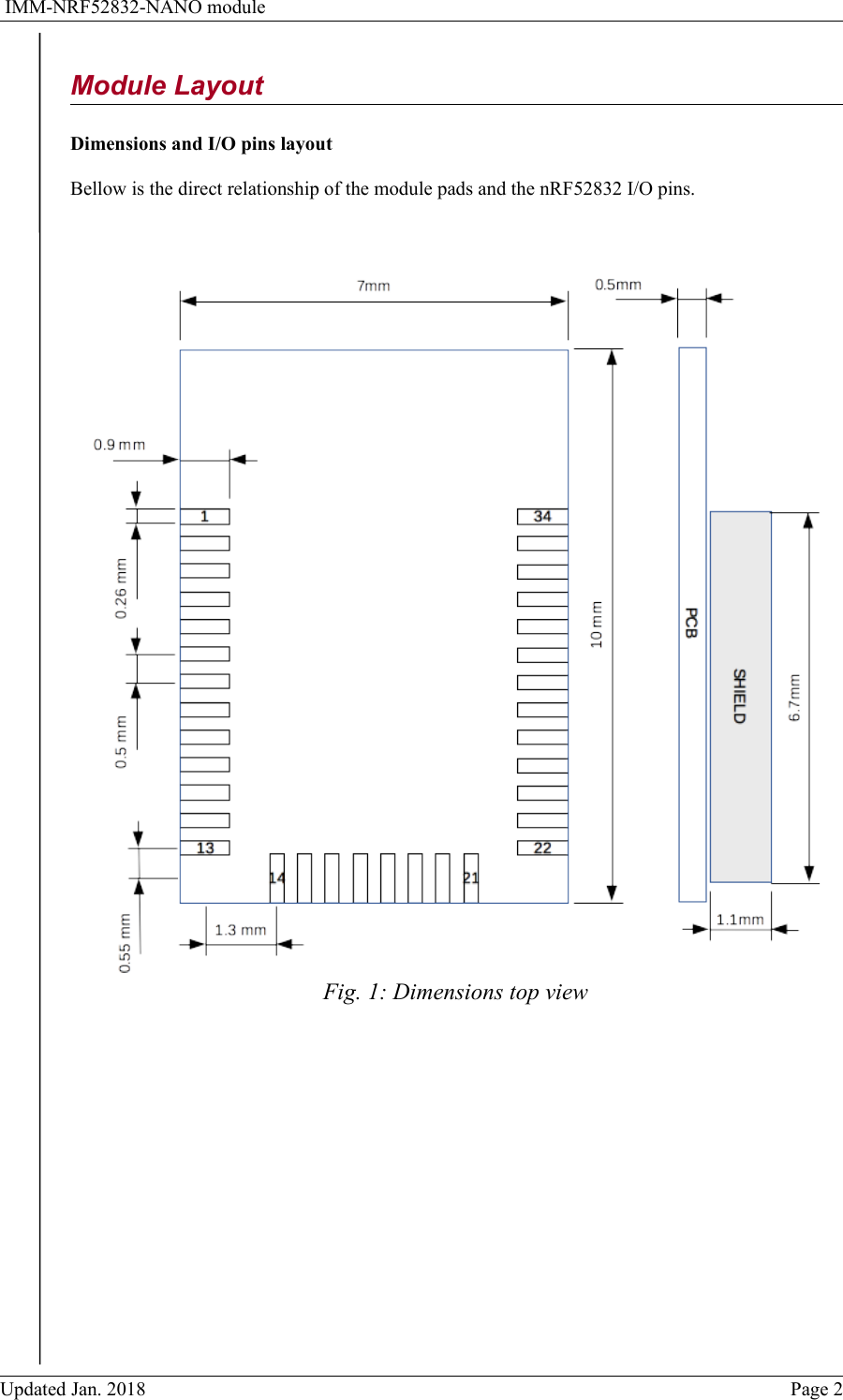
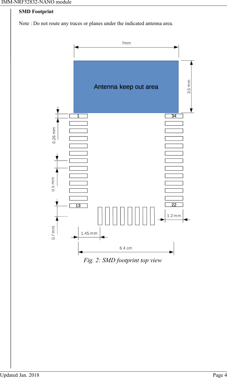
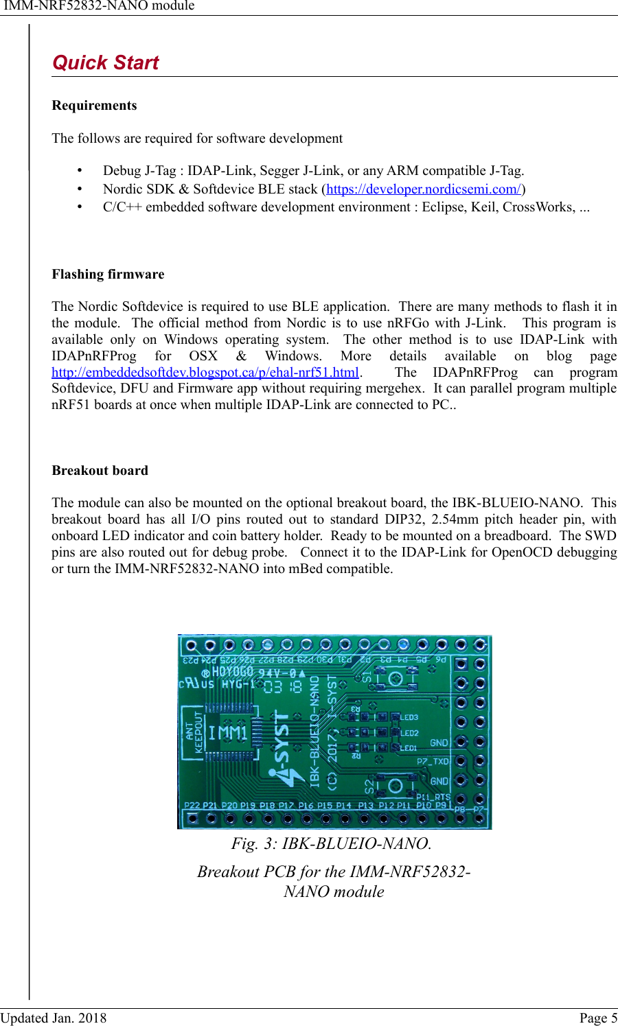
52832NANO User Manual
User Manual
Navigation menu
Upload a User Manual
Namespaces
Wiki Guide
HTML
PDF
Info
Views
User Manual
Discussion / Help
Navigation