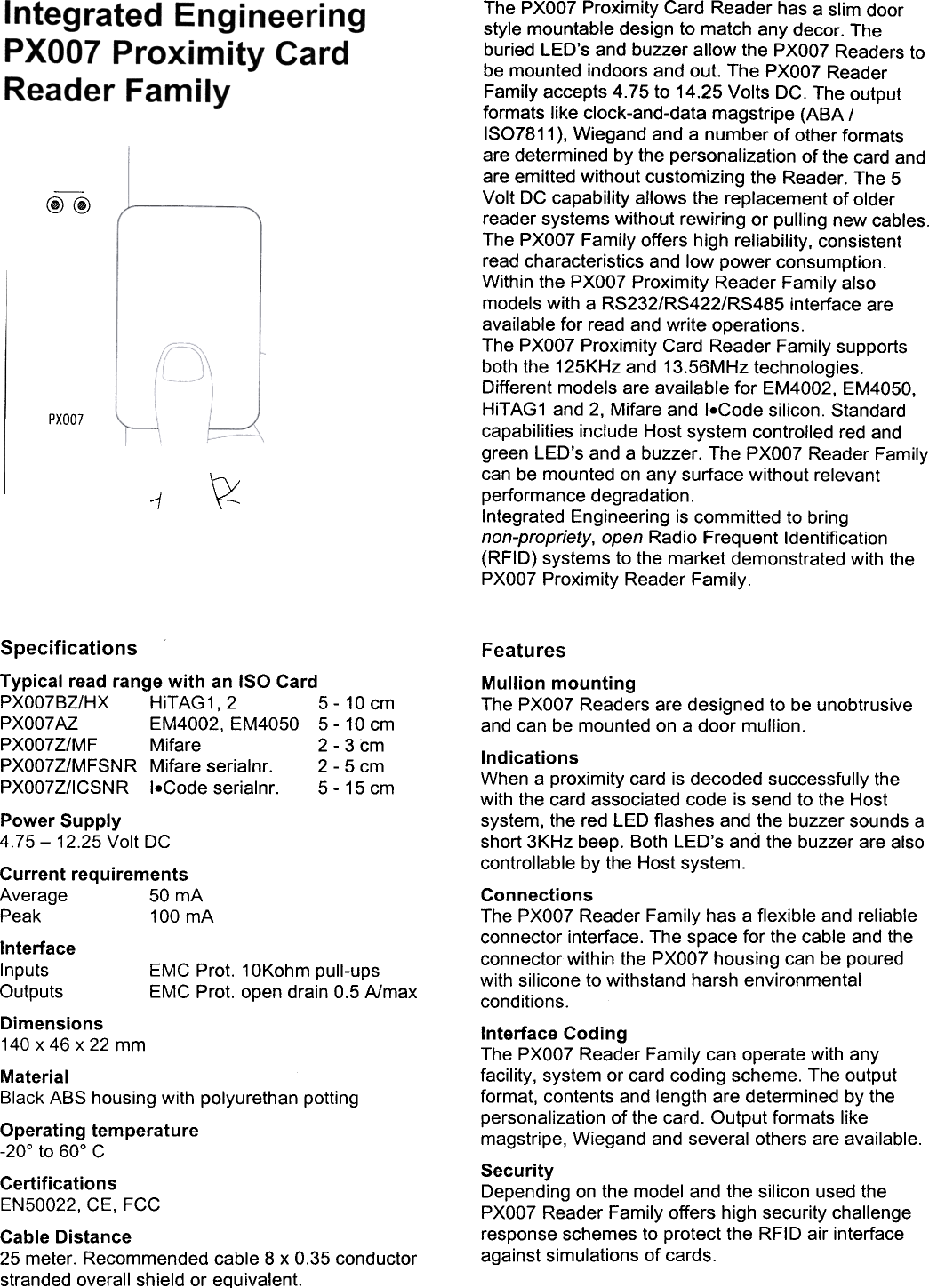
Integrated Engineering I-MSNRPOX-02 Inductive proximity card reader User Manual

Integrated Engineering BV Inductive proximity card reader

user manual

@@PXOO7~1The  PXOO7 Proximity  Card  Reader  has  a slim  doorstyle  mountable  design  to match  any  decor.  Theburied  LED's  and  buzzer  allow  the  PXOO7 Readers  tobe  mounted  indoors  and  out.  The  PXOO7 ReaderFamily  accepts  4.75  to  14.25  Volts  DC.  The  outputformats  like  clock-and-data  magstripe  (ABA  /ISO7811 ), Wiegand  and  a number  of other  formatsare  determined  by the  personalization  of the  card  andare  emitted  without  customizing  the  Reader.  The  5Volt  DC  capability  allows  the  replacement  of olderreader  systems  without  rewiring  or  pulling  new  cables.The  PXOO7 Family  offers  high  reliability,  consistentread  characteristics  and  low  power  consumption.Within  the  PXOO7 Proximity  Reader  Family  alsomodels  with  a RS232/RS422/RS485  interface  areavailable  for  read  and  write  operations.The  PXOO7 Proximity  Card  Reader  Family  supportsboth  the  125KHz  and  13.56MHz  technologies.Different  models  are  available  for  EM4002,  EM4050,HiTAG1  and  2,  Mifare  and  I.Code  silicon.  Standardcapabilities  include  Host  system  controlled  red  andgreen  LED's  and  a buzzer.  The  PXOO7 Reader  Familycan  be  mounted  on  any  surface  without  relevantperformance  degradation.Integrated  Engineering  is committed  to  bringnon-propriety,  open  Radio  Frequent  Identification(RFID)  systems  to  the  market  demonstrated  with  thePXOO7 Proximity  Reader  Family.SpecificationsTypical  read  range  with  an  ISO  CardPXO07BZ/HX  HiTAG1,  2  5-  10  cmPXO07AZ  EM4002,  EM4050  5-  10  cmPXO07Z/MF  Mifare  2  -3  cmPXO07Z/MFSNR  Mifare  serialnr.  2-  5  cmPXO07Z/ICSNR  I.Code  serialnr.  5-  15  cmPower  Supply4.75-  12.25  Volt  DCCurrent  requirementsAverage  50  mAPeak  100  mAInterfaceInputs  EMC  Prot.  10Kohm  pull-upsOutputs  EMC  Prot.  open  drain  0.5  A/maxDimensions140  x  46  x  22  mmMaterialBlack  ABS  housing  with  polyurethan  pottingOperating  temperature-20°  to  60°  CCertificationsEN50022,  CE,  FCCCable  Distance25  meter.  Recommended  cable  8  x  0.35  conductorstranded  overall  shield  or  equivalent.FeaturesMullion  mountingThe  PXOO7 Readers  are  designed  to  be unobtrusiveand  can  be  mounted  on  a door  mullion.IndicationsWhen  a proximity  card  is decoded  successfully  thewith  the  card  associated  code  is send  to the  Hostsystem,  the  red  LED  flashes  and  the  buzzer  sounds  ashort  3KHz  beep.  Both  LED's  and  the  buzzer  are  alsocontrollable  by the  Host  system.ConnectionsThe  PXOO7 Reader  Family  has  a flexible  and  reliableconnector  interface.  The  space  for  the  cable  and  theconnector  within  the  PXOO7 housing  can  be  pouredwith  silicone  to withstand  harsh  environmentalconditions.Interface  CodingThe  PXOO7 Reader  Family  can  operate  with  anyfacility,  system  or card  coding  scheme.  The  outputformat,  contents  and  length  are  determined  by thepersonalization  of  the  card.  Output  formats  likemagstripe,  Wiegand  and  several  others  are  available.SecurityDepending  on  the  model  and  the  silicon  used  thePXOO7 Reader  Family  offers  high  security  challengeresponse  schemes  to  protect  the  RFID  air  interfaceagainst  simulations  of cards.
Connector  AssignmentsPXOO7BZ/HXPXOO7AZPXOO7Z/MFPXOO7Z/MFSNRPXOO7Z/ICSNR1  <;::J Red  LED  input2  <;::J Green  LED  input3  q  Data  /  D14  q  Clock  /  DO5  <;::J Buzzer  input6  NC7  <;::J Ground8  <;::JPowerPXOO7BZ/HX/RS232PXOO7Z/MF/RS232PXOO7Z/MFSNR/RS232PXOO7Z/ICSN  R/RS2321  <:::J Red  LED  input2  <:::J Green  LED  input  i3  q  RS232  RTS  (optiona~)4  q  RS232  TXD5  <:::J RS232  CTS  (optionaO6  <:::J RS232  RXD7  <:::J Ground8  <:::J PowerPXOO7BZ/HX/RS422PXOO7Z/MF/RS422PXOO7Z/MFSNR/RS422PXOO7Z/ICSNR/RS4221  ?  Red  LED  input2  ?  Green  LED  input3  c::> RS422  TXB4  c::> RS422  TXA5  ?  RS422  RXB6  ?  RS422  RXA7  ?  Ground8  ?PowerParts  List1)  PXO07 Reader  4.75-12.25  VDC  qty  12)  Terminal  Connector  8 pins  qty  13)  Mounting  sticker  qty  24)  Installation  sheet  qty  15)  K25  spacer  plate  (optional)  qty  16)  Cable,  8 x 0.35  conductor  as  requiredInstallation  instruction1)  Determine  an appropriate  position  for theReader  and  drill  two  holes  for  mounting  thereader  to  the  surface  (see  diagram).  Make  surethat  enough  room  to connect  the  cable  isallowed.  Protect  the  cable  against  sharp  edgesand  any  damage  from  chaffing.2)  Remove  the  Terminal  Connector  8 pins  from  theback  of the  Reader.  Use  a small  flat  headscrewdriver  to loosen  off  all  of the  terminals.The  end  of the  cable  should  be prepared  bycutting  it back  to expose  the  wires  and  each  endshould  be  twisted  to  eliminate  any  loose  orfrayed  wires.3)  The  wires  should  then  be connected  to theReader  inline  with  the  Connector  Assignments.4)  After  wiring  the  reader  and  the  Host  system  theReader  is ready  to  be tested.  Apply  power  andpresent  a Card  to the  Reader.  The  red  LEDshould  flash  and  the  buzzer  should  beepindicating  a read.  If the  Host  system  isconnected  to the  red  and  green  LED  inputsthese  should  follow  the  functionality  of the  Hostsystem.5)  The  Reader  should  now  be secured  to thesurface  using  the  appropriate  fasteners  and  thestickers  should  be  applied  to cover  themounting  holes.Mullion  MountingIntegrated  EngineeringAmsterdamThe  NetherlandsTelephone:  +31  204620755Fax:  +31  204620756Email:  info@ieprox.co$}WWW:  http://www.iepr~x.comRef:  V1.2,  20/11/2000

Navigation menu