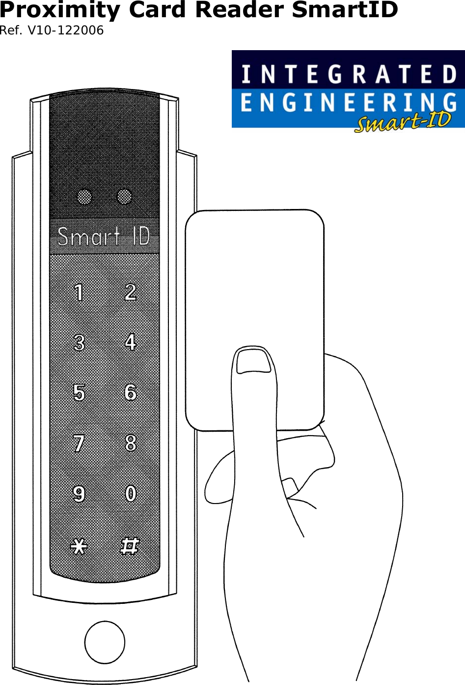
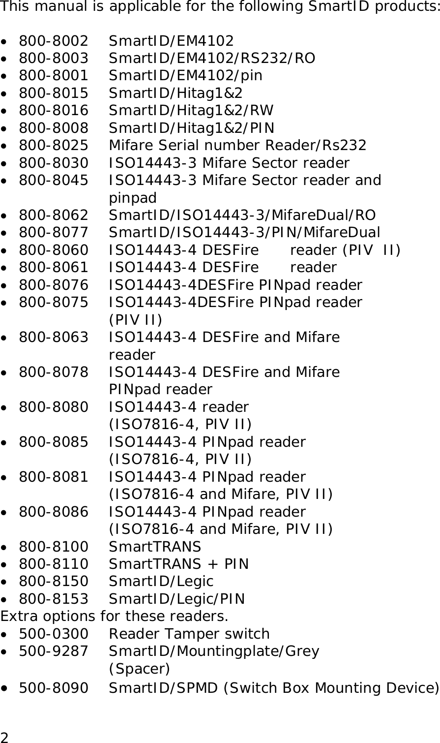
Integrated Engineering SMARTPIN-8 Inductive Proximity Card Reader User Manual Proximity Card Reader SmartID

Integrated Engineering BV Inductive Proximity Card Reader Proximity Card Reader SmartID

Users Manual

Proximity Card Reader SmartID  Ref. V10-122006
This manual is applicable for the following SmartID products:  •  800-8002    SmartID/EM4102 •  800-8003 SmartID/EM4102/RS232/RO •  800-8001    SmartID/EM4102/pin •  800-8015    SmartID/Hitag1&2 •  800-8016    SmartID/Hitag1&2/RW  •  800-8008 SmartID/Hitag1&2/PIN •  800-8025    Mifare Serial number Reader/Rs232 •  800-8030    ISO14443-3 Mifare Sector reader •  800-8045    ISO14443-3 Mifare Sector reader and  pinpad  •  800-8062 SmartID/ISO14443-3/MifareDual/RO •  800-8077 SmartID/ISO14443-3/PIN/MifareDual •  800-8060    ISO14443-4 DESFire   reader (PIV  II) •  800-8061 ISO14443-4 DESFire   reader •  800-8076 ISO14443-4DESFire PINpad reader •  800-8075    ISO14443-4DESFire PINpad reader (PIV II) •  800-8063  ISO14443-4 DESFire and Mifare reader •  800-8078  ISO14443-4 DESFire and Mifare PINpad reader •  800-8080 ISO14443-4 reader  (ISO7816-4, PIV II) •  800-8085  ISO14443-4 PINpad reader  (ISO7816-4, PIV II) •  800-8081  ISO14443-4 PINpad reader  (ISO7816-4 and Mifare, PIV II) •  800-8086  ISO14443-4 PINpad reader  (ISO7816-4 and Mifare, PIV II) •  800-8100 SmartTRANS •  800-8110 SmartTRANS + PIN  •  800-8150 SmartID/Legic  •  800-8153 SmartID/Legic/PIN Extra options for these readers.  •  500-0300   Reader Tamper switch •  500-9287    SmartID/Mountingplate/Grey               (Spacer) •  500-8090  SmartID/SPMD (Switch Box Mounting Device)  2
Table of content:   Features............................................................. 4 Mullion Mounting ............................................... 5 Indications......................................................... 5 Connections ....................................................... 5 Output protocols ................................................ 6 Security ............................................................. 6 Specifications..................................................... 6 Typical read range with an ISO Card......................6 Power Supply......................................................6 Power requirements.............................................7 Interface............................................................7 Dimensions ........................................................7 Material .............................................................7 Operating temperature ........................................7 Certifications ......................................................7 Cable Distance....................................................9 SIA recommended cable type for Wiegand signals ...9 Wiegand Signal Levels .........................................9 Reader output interface and pull-up resistors ........10 Timing...............................................................11 Installation instruction .....................................12 Mullion Mounting ..............................................14 Connector Assignments ....................................15 Tamper Switch ..................................................16 Mounting tool....................................................17 Mounting Plate (Spacer) ...................................19 Notes ...............................................................20  3
Features The Smart ID Reader has a slim door style mountable design to match any decor. The sunk LED’s and buzzer allow the Smart ID Readers to be mounted indoors and outdoors.   The Smart ID Reader accepts 5 to 12 Volts DC. The  reader output formats like clock-and-data magstripe (ABA / ISO7811), Wiegand and a number of other formats are determined by the personalization of the card or configuration of the reader. The 5 Volt DC capability allows the replacement of older reader systems without rewiring or pulling new cables. The Smart ID Reader offers high reliability, consistent read characteristics and low power consumption.   Within the Smart ID Proximity Reader Family also models with a RS232/RS422/RS485 interface are available for read-only and read/write operations.   The Smart ID Reader Family supports both the 125KHz and 13.56MHz technologies. Different models are available for EM4102, HiTAG1 and 2, Mifare, DESFire, Legic and I·Code technology.   Standard capabilities include Host system controlled red and green LED’s and a buzzer.    4
The Smart ID Reader can be mounted on any surface without relevant performance degradation. For mounting on a metal surface a spacer is advised.  Our commitment is to bring non-propriety, open Radio Frequent Identification (RFID) systems to the market demonstrated with the Smart ID Reader Family.   Mullion Mounting The Smart ID Readers can be mounted on a door mullion.  Optional there is a mounting kit available in case the small Smart ID reader will be mounted over a wall box   (mounting US back box, vertical 84 milimeter (3.31 inch), mounting European back box, horizontal 60 millimeter (2.36 inch)).  Indications When a proximity card is decoded successfully the with the card associated code is send to the Host system  and the buzzer sounds a short 3KHz beep. Both LED’s and the buzzer are also controllable by the Host system.  Connections The Smart ID Reader Family has a flexible and reliable connector interface. The space for the cable and the connector within the Smart ID housing can be sealed with silicone to withstand harsh environmental conditions.   5
Output protocols The Smart ID Reader Family can operate with any facility, system or card coding scheme. The output format, contents and length are determined by the personalization of the card or configuration of the reader. Output formats like magstripe, Wiegand and several others are available.  The readers are intended for connection to an Access Control Panel where compatibility to the reader is referenced in the control unit’s installation instructions.  Security Depending on the model and the RF technology used the Smart ID Reader Family offers high security challenge response schemes to protect the RFID air interface against various attacks schemes like record & playback attacks.   Specifications  Typical read range with an ISO Card EM4102   up to 7.5 cm (2.9 inch)  Hitag1&2      up to 8 cm (3.2 inch) ISO14443    up to 3 cm (1.2 inch)  Legic    up to 4 cm (1.6 inch)  ISO15693    up to 15 cm (5.9 inch)  DESFire    up to 2 cm (0.8 inch)   Power Supply 4,5 – 16 Volt DC   6
Power requirements ISO 14443 readers Average Power Consumption  1500 mW Peak Power Consumption   2000 mW  SmartTRANS (ETL-listed) Average Power Consumption  1400 mW Peak Power Consumption   2500 mW  Legic Average Power Consumption  600 mW Peak Power Consumption   1200 mW  125 kHz readers  Average Power Consumption  860 mW Peak Power Consumption   940 mW  Interface Inputs  EMC Prot. 10K ohm pull-ups  Outputs EMC Prot. open drain 0.5 A/max  Dimensions 142 x 46.2 x 25 mm (5.59 x 1.81 x 0.98 inch)  Material Enclosure: PC/ABS with polyurethane potting  Operating temperature -30° to 60° C (-22 to 140 Fahrenheit)   Certifications CE, FCC, IC, ETL  Black cover: Polycarbonate 943   7
FCC ID's are: •  EM4102: SmartID/EM4102 (125 kHz) P4E-SMARTPIN-2 •  Hitag1&2: SmartID/Hitag1&2 (125 kHz) P4E-SMARTPIN-2 •  ISO14443: SmartID/ ISO14443/SNR/RS232 P4E-SMARTPIN-8 •  ISO 14443-3: SmartID/ISO14443-3/Sect P4E-SMARTPIN-8 •  DESFire: SmartID/DESFire P4E-SMARTPIN-8 •  Legic: SmartID/Legic P4E-Smartpin-5 •  ISO 14443 & 125 kHz Prox: SmartTRANS P4E-SMARTPIN-4   Consult your National Authority if any  authorization is needed for this product. This device complies with Part 15 of the FCC Rules. Operation is subject to the following two conditions: 1)  that this device does not cause harmful interference, and 2)  that this device must accept any interference received, including interference that may cause undesired operation.   ETL Listing •  800-8100 SmartTrans •  800-8110 SmartTrans + PIN   8Changes or modifications not expressly approved by the manufacturer could void the user's authority to operate the  equipment.
Cable Distance Up to 153 meter (502 foot), depending on output protocol and cable type. Recommended cable type: stranded conductor with overall stranded shield or equivalent   SIA recommended cable type for Wiegand signals  Cable Length  Cable  Diameter inch Diameter mm Up to 61m (200.1 ft)  AWG22  0.025  0.64 Up to 91m (301.8 ft)  AWG20  0.03  0.82 Up to 153m (502 ft)  AWG18  0.04  1.02  Recommended cable for clock and data ABA track 2 emulation: Up to 25 meter (82 foot), AWG22.  Voh = Output Voltage idle high Vol = Output Voltage active low  Wiegand Signal Levels  9
Reader output interface and pull-up resistors The SmartID readers provided true open collector outputs for Wiegand/Clock&Data ABA track 2 emulation. This means the data output is not voltage driven.  External pull-up resistors are required when the controller does not provide internal pull-up resistors. The typical value for the pull-up resistors is 1 kOhm. The recommend position to place the pull-up resistors is at the controller side.  The pull-up resistor #1 connects form Data/D1 (reader connector pin 3) to a 5 Volt reference.  The pull-up resistor #2 connects form Clock/D0 (reader connector pin 4) to a 5 Volt reference.  10
Timing   11
Installation instruction 1)  Determine an appropriate position for the Reader and drill two holes for mounting the reader to the surface (see mullion mounting drawing on 13). Do not mount the readers less than 20 cm (7.87 inch) from each other. Make sure that enough room to connect the cable is allowed. Protect the cable against sharp edges and any damage from chaffing.   2)  Remove the Terminal Connector 8 pins from the back of the Reader. Use a small flat head screwdriver to loosen off all of the terminals. The end of the cable should be prepared by cutting it back to expose the wires and each end should be twisted to eliminate any loose or frayed wires.  3)  The wires should then be connected to the Reader inline with the Connector Assignments. Wire ends outside the shielding and optional permanent  LED links should be kept as short as possible. Twist the connector a few times to twine the wire ends to avoid differential mode interference on the data lines.  Note:  wires at the connector must be kept as short as possible: long, unshielded connections will reduce the sensitivity of the reader.   12
 4)  After wiring the reader and the Host system the Reader is ready to be tested. Apply power and present a Card to the Reader. The green LED should flash and the buzzer should beep indicating a read. If the Host system is connected to the red and green LED inputs these should follow the functionality of the Host system.  5)  The Reader can now be secured to the surface using the appropriate screws. Mount the black cover (sticker) and mount the cap over the mounting hole.    13
Mullion Mounting The size in the drawing is in mm. 1 mm is 0.039 inch.   14
Connector Assignments  input  Do not connect   Wiegand RS232  RS422 Clock/Data (ABA) RS485   Do not Connect 1  Green LED input  Green LED input  Green LED input)** Do not Connect  RXD  RXB   Green LED input)**  Green LED input)**   2  Red LED input  Red LED input  Red LED input)**  Red LED input)**  Red LED input)**   3  Data  D1  Do not connect  TXA  D0  TXD  TXB  TRX  5  Buzzer input 16.00 VDC Power   4.5 to  TRX 16.00 VDC   4 Attention: 4.5 Volt DC is MINIMUM VOLTAGE AT READER CONNECTOR PINS Clock   Buzzer  RXA  Do not Connect  Do not Connect 6  Ground  Ground  Ground  Ground  Ground 7         8 Power  Power  Power  Power 4.5 to   4.5 to   4.5 to   4.5 to  16.00 VDC  16.00 VDC  16.00 VDC Optional tamper contact: rating 1A 30 VDC  ** LED input only valid in read-only applications  15
Optional Tamper Switch                                  16
Optional Mounting tool The sizes in the drawing is in mm. 1 mm is 0.039 inch. 17
  18
Optional  Mounting Plate (Spacer)  The sizes in the drawing is in mm. 1 mm is 0.039 inch.   19
  The crossed-out wheeled bin means that within the European Union the product must be taken to separate collection at the product end-of life. This applies to your device but also to any enhancements marked with this symbol. Do not dispose of these products as unsorted.    20Approval If used according to the instructions, this radio system meets the basic requirements of article 3 and the remaining applicable conditions of the R&TTE directive (1999/5/E6) of March 1999.        © Copyright 2007 Issue: May 2007 – This manual supercedes and renders invalid all earlier versions. The information in this manual can be changed without prior notice.  The information in this manual has been put together to the best of the authors’ knowledge and conscience. The manufacturers accepts no liability for the accuracy or completeness of the information in this manual. In particular, the manufacturer cannot be held liable for consequential damages caused as a result of incorrect or incomplete information. As it is impossible to avoid mistakes despite all our efforts, we are always grateful if these are pointed out.  The installation recommendations contained in this manual assume the most favorable framework conditions. The manufacturer cannot guarantee that the system will function perfectly under other conditions.  The manufacturer cannot guarantee that the information contained in this document is not protected by external property rights. The manufacturer is not granting licenses to its own or external patents or other property right.

Navigation menu