Ixia EE11ABG 802.11 a/b/g Emulation Engine User Manual EmulationEngine 11a b g User s Guide
Ixia 802.11 a/b/g Emulation Engine EmulationEngine 11a b g User s Guide
Ixia >
Contents
- 1. User Manual 1 of 3
- 2. User Manual 2 of 3
- 3. User Manual 3 of 3
User Manual 3 of 3
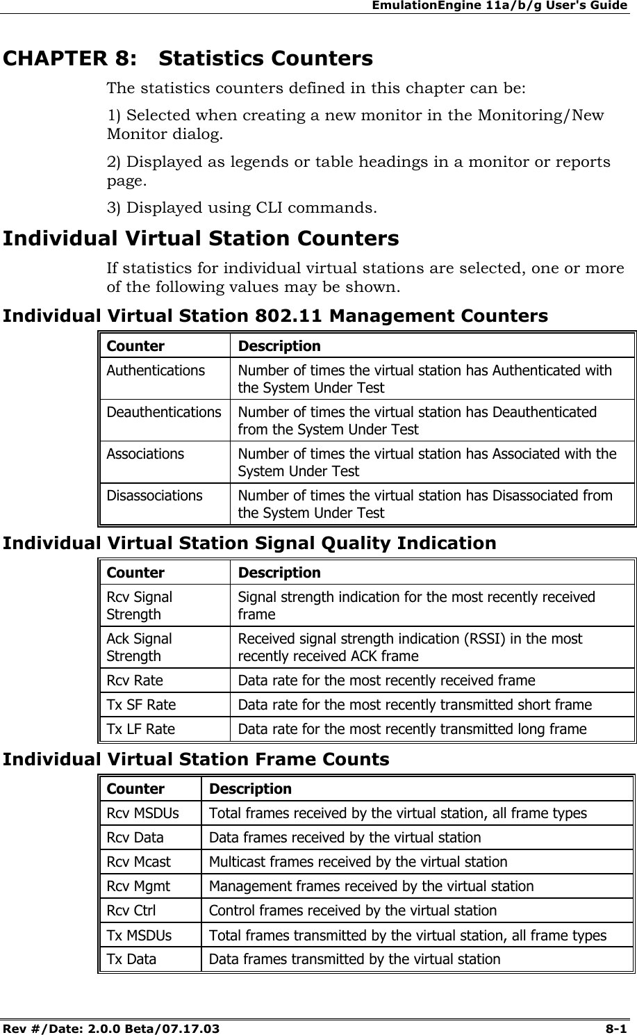
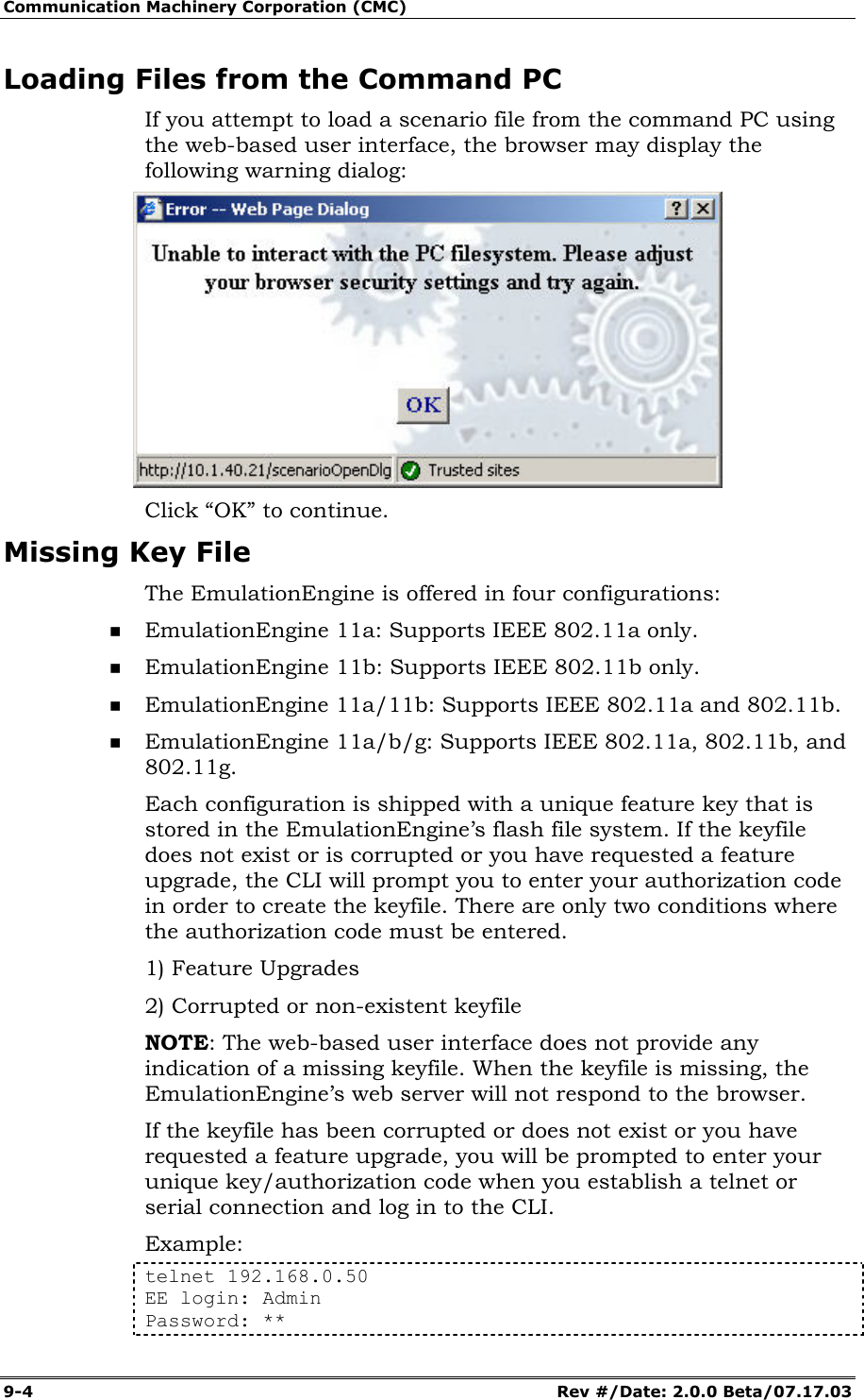
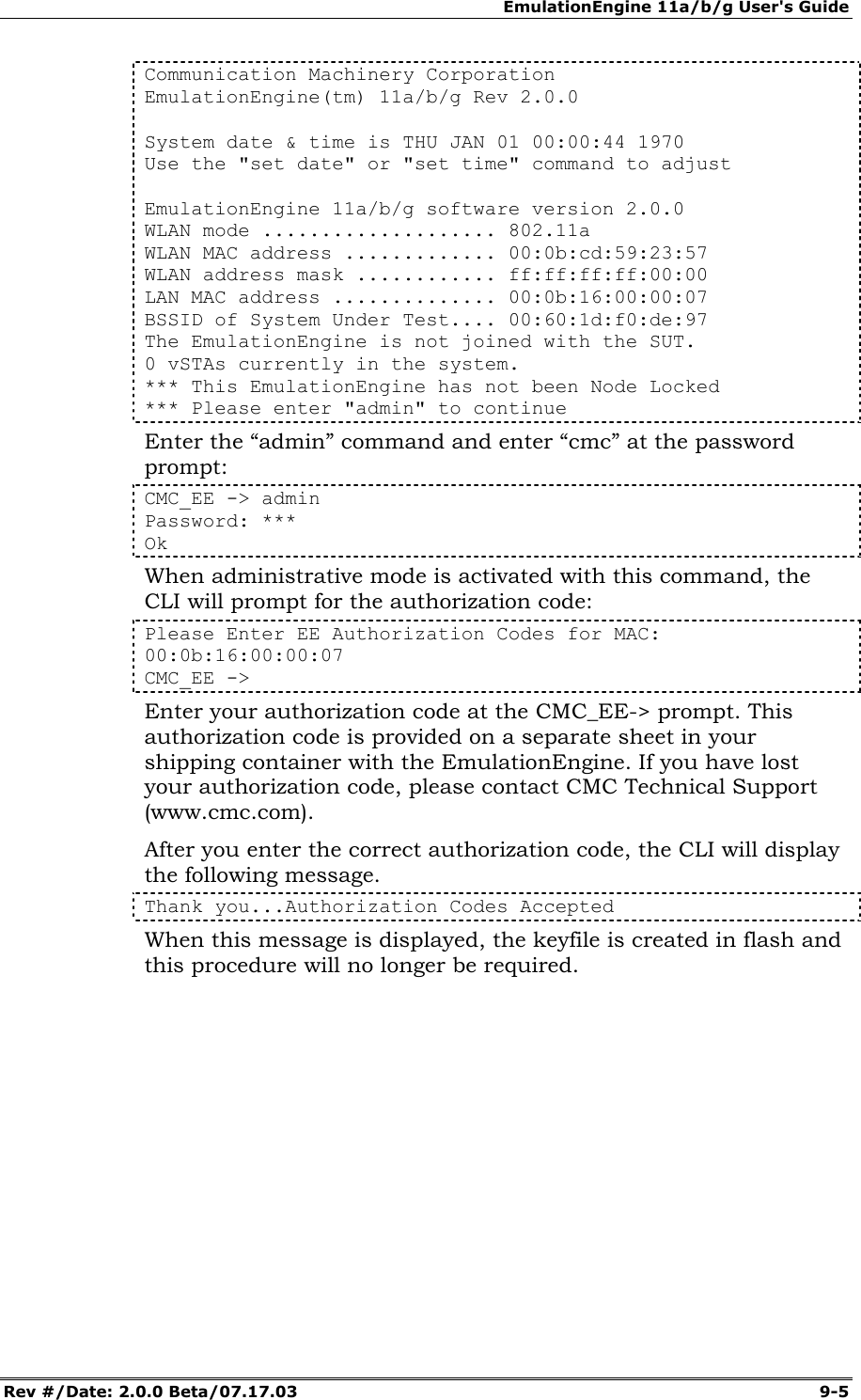
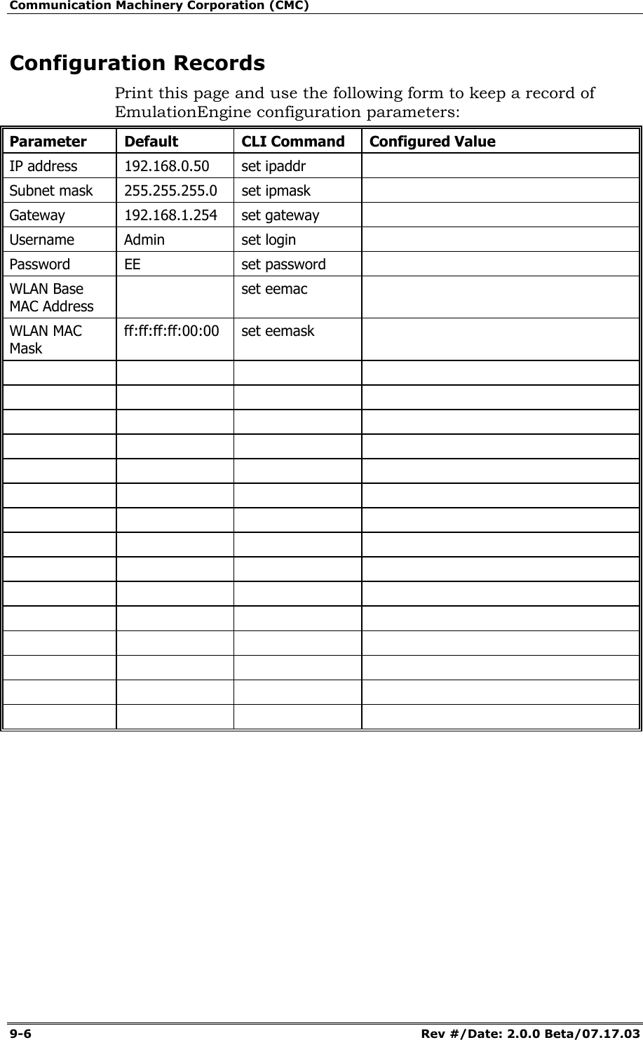
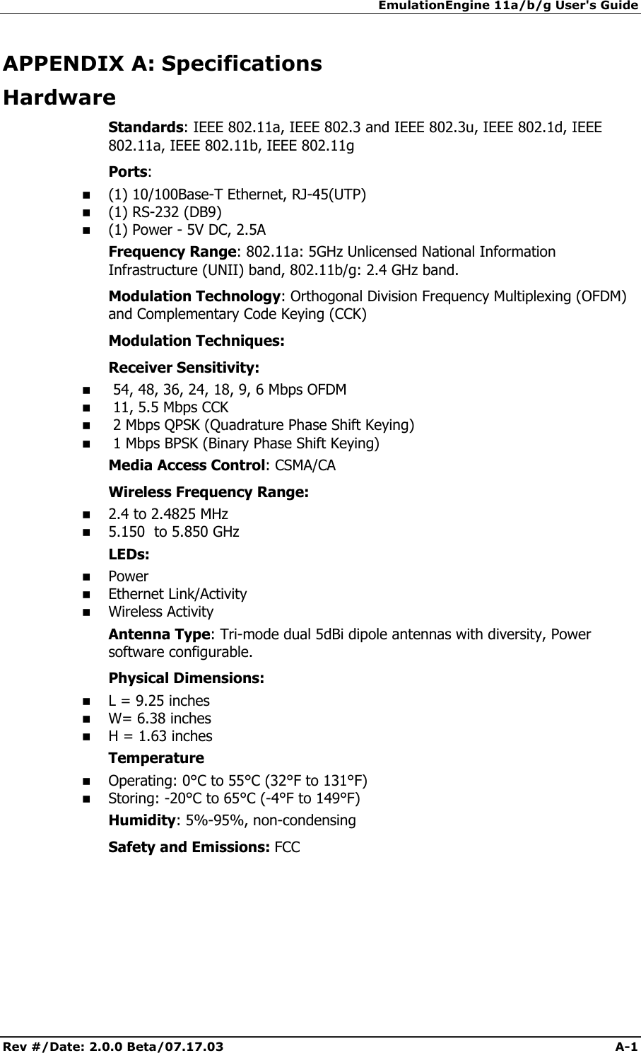
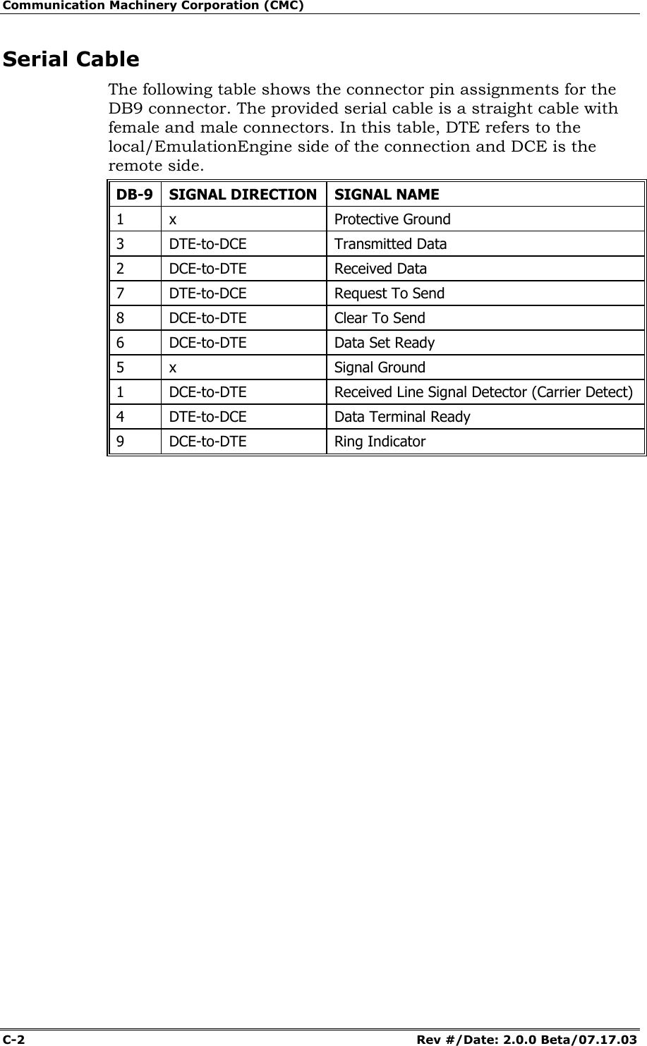
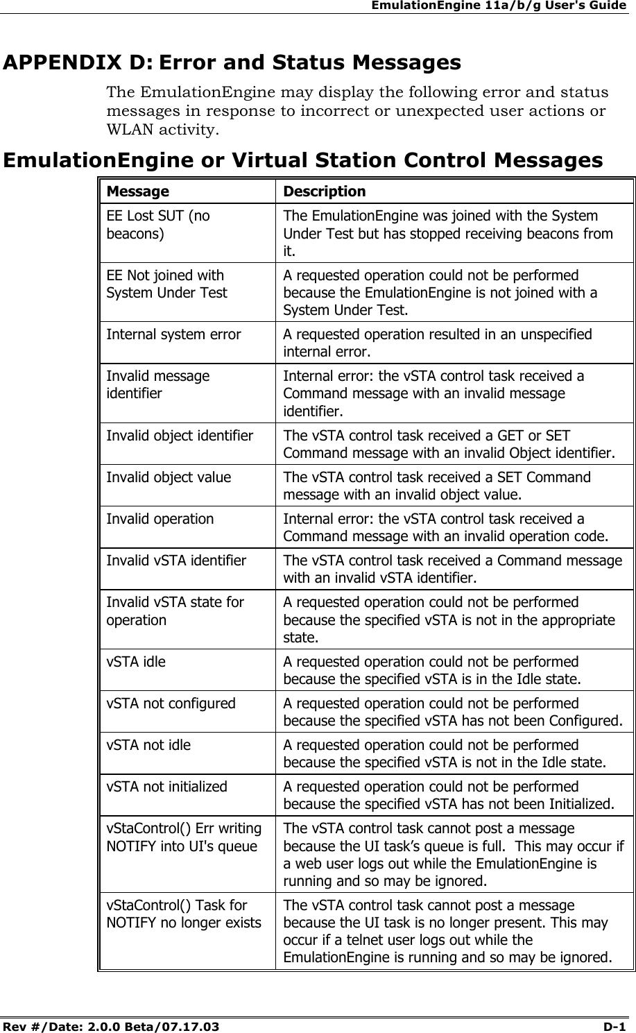
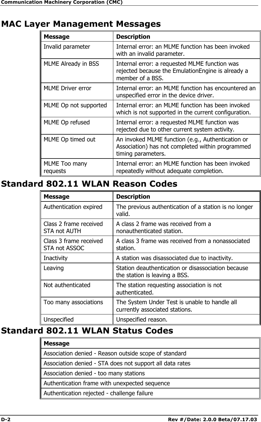
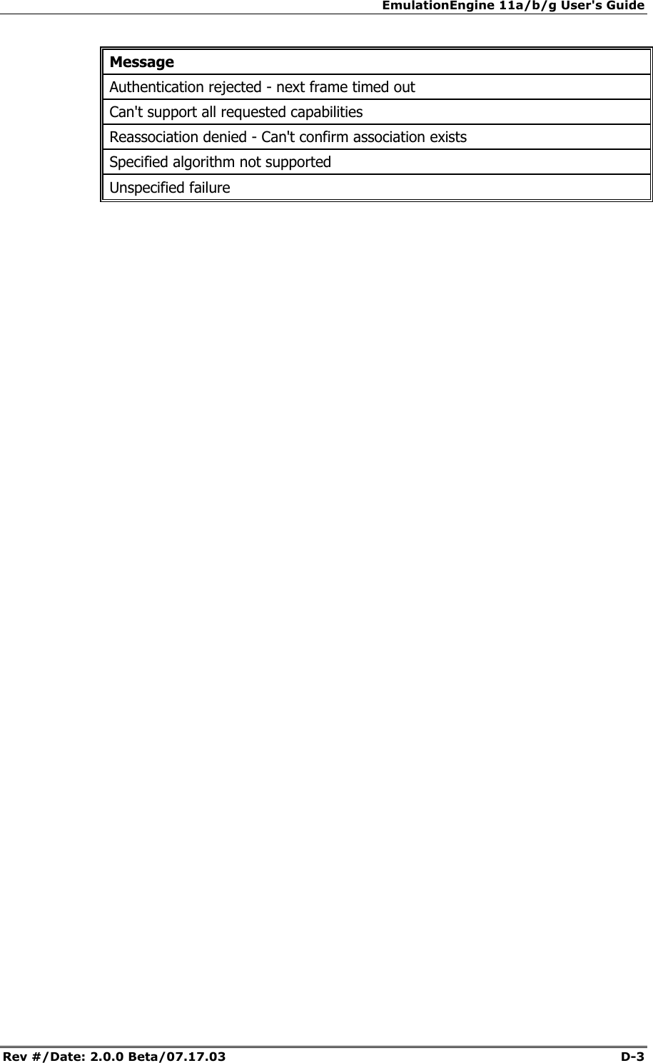
![EmulationEngine 11a/b/g User's Guide Rev #/Date: 2.0.0 Beta/07.17.03 7-1 CHAPTER 7: Event Logging Overview During normal operation, the EmulationEngine processes and can log various types of events. When an event is logged, a record of the event is stored for future analysis. The event record includes a timestamp, an indicator of the type of event that occurred, and a limited amount of data to describe the event. Event logging is controlled on three levels: 1) master enable (controlled by set evlog enable/disable) 2) verbosity level (controlled by set evlog level <level>) 3) module enable (controlled by set evlog module <module name> enable/disable) 1) The master enable controls whether event logging occurs at all. The master control is independent of other filters. If "set evlog disable" is used, enabling event logging for a particular module has no effect. 2) The verbosity level sets an “importance” threshold for events: at lower verbosity, only more “important” events are logged; at higher verbosity, less important events may also be logged. 3) Each event is processed by a given module or process within the EmulationEngine. The various processes of the system can be individually enabled for event logging. The event logging function stores event records into a buffer area in memory. The log buffer is a circular buffer that can hold 512 event records. The "get evlog buffer" command can be used to display the contents of the buffer at any time. Event data can also be written to a log file in Flash. When writing to a file is enabled by the "set evlog file enable" command, the log buffer is flushed to a file every 30 seconds or every time it wraps at the 512-record limit (which ever comes first). There are two log files, A and B. The EmulationEngine will alternate between the two files so that at least one full file is available at any given time. Each log file can store up to 4,000 event records. You can display the records stored in either file using the "get evlog file A" and "get evlog file B" CLI commands. Event Record Format Event records are printed in the following format: [header]: [message] [optional parameters] Example: 12/27/2002,9:59:57,2296.320226,11396: RX: ok pDesc 0x9326c0 hwStatus 01cd803c:0be20203 numRxDesc 9643712](https://usermanual.wiki/Ixia/EE11ABG.User-Manual-3-of-3/User-Guide-352253-Page-1.png)
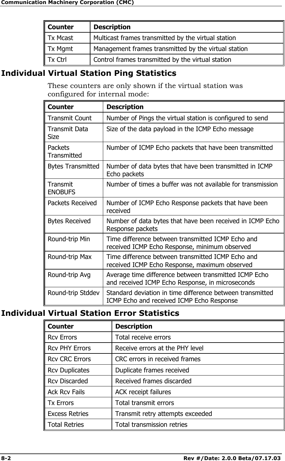
![Communication Machinery Corporation (CMC) 7-2 Rev #/Date: 2.0.0 Beta/07.17.03 where: [header] is a standard header consisting of a timestamp, microsecond clock reference and sequence number (e.g.: 12/27/2002,9:59:57,2296.320226,11396) timestamp = 12/27/2002,9:59:57 (time the event occurred, taken from the system clock) microsecond clock reference = 2296.320226 (in seconds, resolution to 1 microsecond, not sync’ed to timestamp) sequence number = a sequential number assigned to each record (e.g., 11396; next event would be 11397, 11398, etc.) [message] is very brief text string (typically < 15-20 characters) indicating the type of event that occurred (e.g.: RX: ok indicates a valid 802.11 frame received without error). [optional parameters] describe the specific circumstances of this particular occurrence of the event. It can be up to four 32-bit parameters. Example: pDesc 0x9326c0 hwStatus 01cd803c:0be20203 numRxDesc 9643712. CLI Commands The following CLI commands control event logging: set evlog enable/disable: This is the master control to enable or disable event logging (i.e., to the event log buffer in RAM). The default is enabled. set evlog level <level>: This command sets the verbosity level (0/critical, 1/low, 2/medium, or 3/high) for event logging. The default is critical. set evlog module <module> enable/disable: This command enables or disables logging events from the specified module or process: EmulationEngine control events, virtual station control events, WLAN transmit and receive events, and User Interface events. By default, the following processes are enabled for event logging: EmulationEngine control events and virtual station control events. The following processes are disabled for event logging: WLAN transmit and receive events and User Interface events. set evlog console enable/disable: This command enables or disables logging directly to the console. The default is disabled. set evlog file enable/disable: This command enables or disables recording logged events to file. The default is disabled. get evlog settings: This command shows the current event log control settings.](https://usermanual.wiki/Ixia/EE11ABG.User-Manual-3-of-3/User-Guide-352253-Page-2.png)
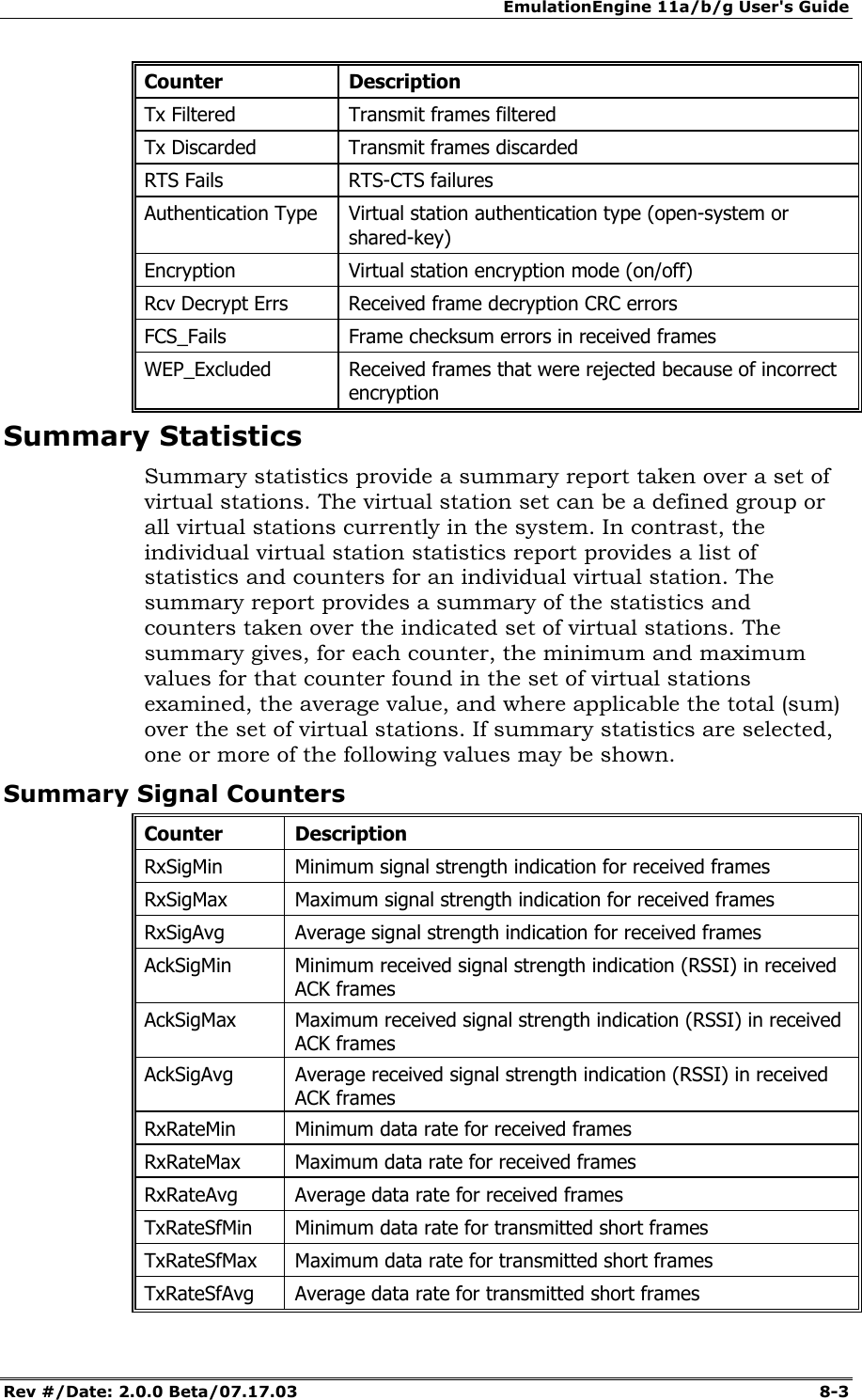
![EmulationEngine 11a/b/g User's Guide Rev #/Date: 2.0.0 Beta/07.17.03 7-3 get evlog buffer [n] – This command prints the last n events logged to the log buffer in memory. If [n] is omitted or zero, all events currently in the log buffer will be displayed. get evlog file A/B <startRec#> <count>: This command prints event records in log file A or B. If no starting record number <startRec#> is given, records are displayed starting with the first record in the file. If no count of records is given, all records are displayed. You can also use "?" to display the number of records in the file. clear evlog file A/B: This command clears all event records from log file A or B clear evlog buffer: This command clears all event records from the log buffer. save evlog: This command flushes all records from the log buffer to the log file, even if log to file is not enabled. NOTE: Event log control settings are not permanent. They are not saved with other configuration controls. They must be entered following startup as desired to change event log operation from the default settings indicated above. The Web-Based User Interface You can configure and display the event log by selecting the Logging tab in the web-based user interface side bar. See the "Event Log Side Bar" in Chapter 5 for details.](https://usermanual.wiki/Ixia/EE11ABG.User-Manual-3-of-3/User-Guide-352253-Page-3.png)