JWM Hi tech Development WM-5000GT GUARD TOUR SYSTEM User Manual
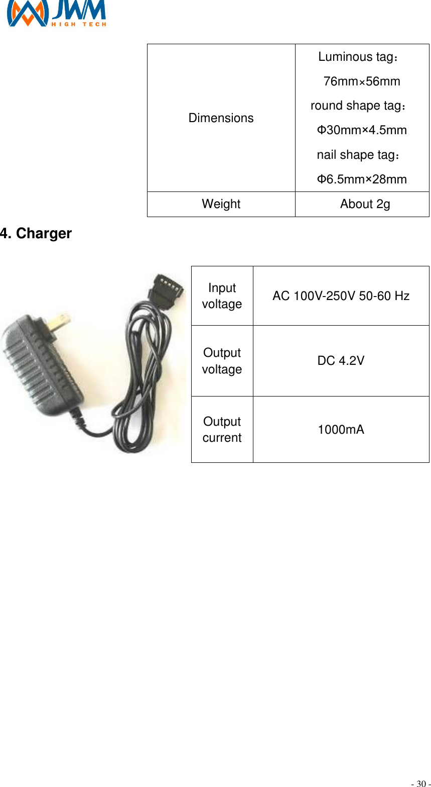
JWM Hi-tech Development Co., Ltd GUARD TOUR SYSTEM Users Manual
UserManual.wiki
>
JWM Hi tech Development
>
WM 5000GT User Manual
Users Manual
Navigation menu
Upload a User Manual
Namespaces
Wiki Guide
HTML
PDF
Info
Views
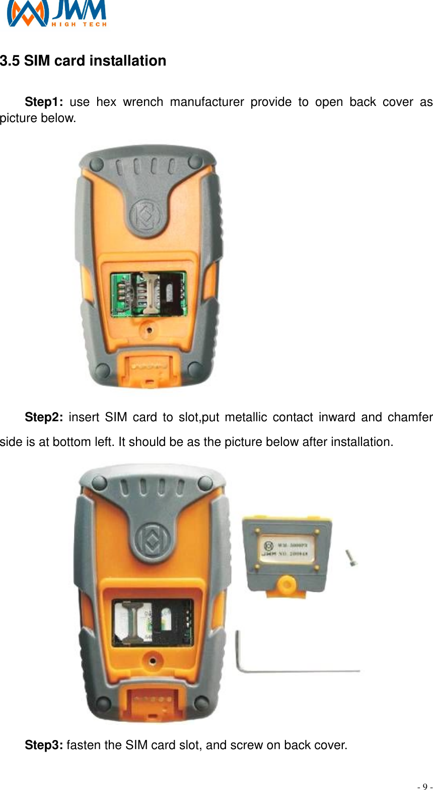
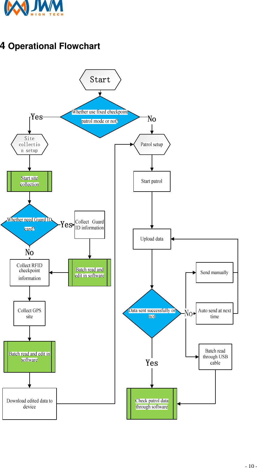
User Manual
Discussion / Help
Navigation