Johnson Outdoors IPCON20 i-Pilot Head Assembly User Manual Part 2
Johnson Outdoors, Inc. i-Pilot Head Assembly Users Manual Part 2
UserManual.wiki
>
Johnson Outdoors
>
IPCON20 User Manual
>
Users Manual Part 2
Contents
1.
Users Manual Part 1
2.
Users Manual Part 2
3.
Users Manual Part 3
4.
Users Manual Part 4
5.
Users Manual Part 5 Rev 3
Users Manual Part 2
Navigation menu
Upload a User Manual
Namespaces
Wiki Guide
HTML
PDF
Info
Views
User Manual
Discussion / Help
Navigation
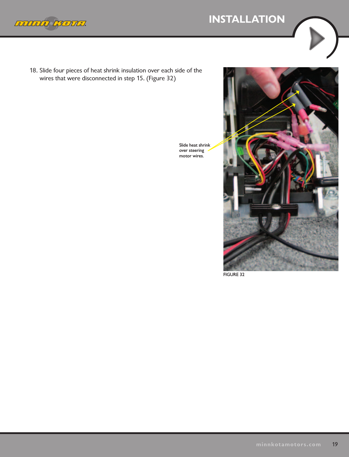
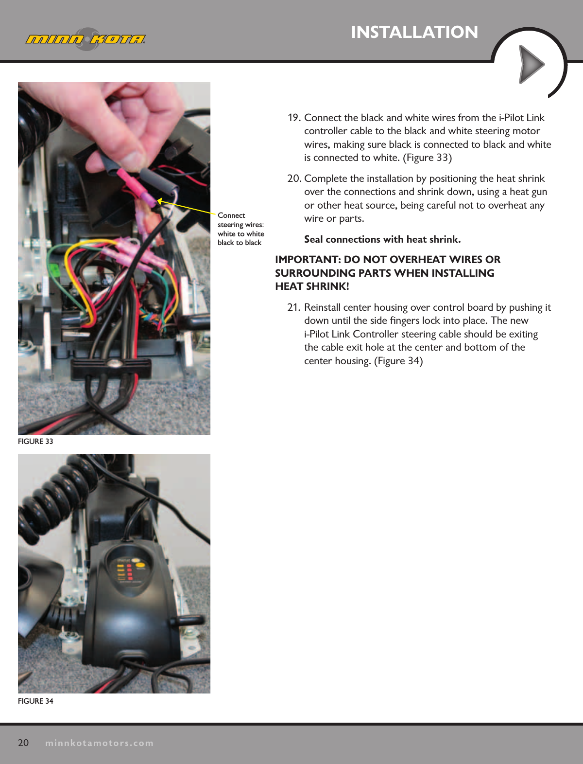
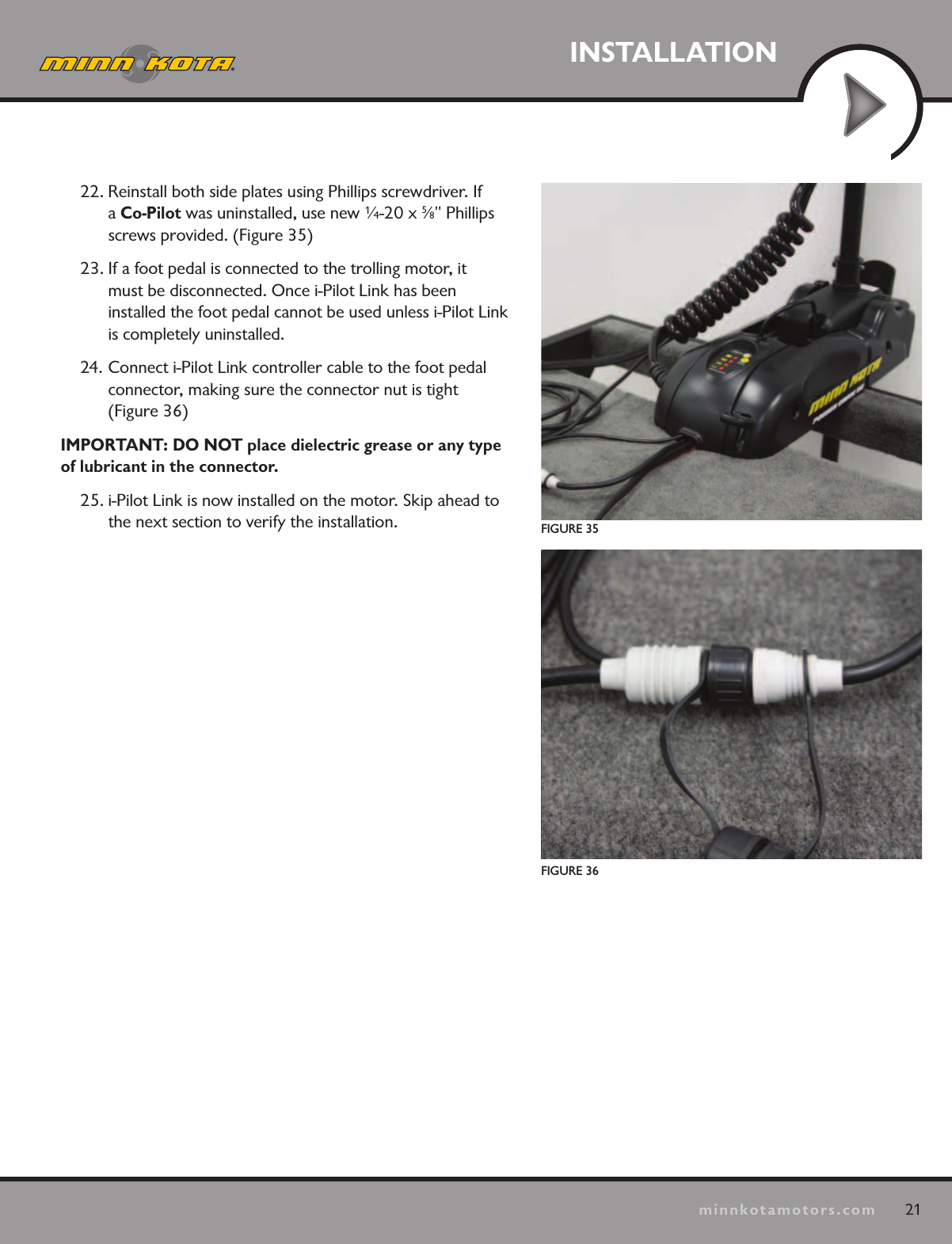
![36minnkotamotors.comGETTING STARTEDHUMMINBIRD SOFTWARE UPDATESSet up an online account at humminbird.com so that you will receive the latest Humminbird news and software updates for your Fishing System. The i-Pilot Link software can also be updated through the control head.WARNING! Humminbird® is not responsible for the loss of data files (waypoints, routes, tracks, groups, snapshots, recordings, etc.) that may occur due to direct or indirect damage to the unit’s hardware or software. It is important to back up your control head’s data files periodically. Data files should also be saved to your PC before restoring the unit’s defaults or updating the software. See your Humminbird® online account at humminbird.com and the Waypoint Management guide.Required Equipment: Personal computer with Internet access, a formatted SD memory card, and a USB Memory Card Reader.Update the Software1. Install a formatted SD memory card into the card reader connected to your PC.2. Register your Fishing System: Log on to humminbird.com. Click My Account. Set up a new account or log into your current account and add the i-Pilot Link to your My Equipment tab.3. Download: From My Account\My Profile\My Equipment, click the file name of the latest software update (unit name [version #]) for your control head. • Read the instructions in the dialog box and click Download.• Follow the on-screen instructions to save the software les directly to the SD Card.4. Repeat step 3 to download the i-Pilot Link controller and remote software files. 5. Install the SD card with the updated software files into the control head card slot.6. Power on your Fishing System.7. Control Head Update: The control head will recognize the new software. Follow the dialog box instructions to confirm software installation. i-Pilot Link: The software will be updated automatically. It may take up to two minutes for the software to be detected on the network, and the control head will display on-screen dialog boxes to indicate that the update is in progress.NOTE: To purchase the USB Memory Card Reader (AS CR), visit our Web site at humminbird.com or contact our Customer Resource Center at 1-800-633-1468. Our Customer Resource Center will also assist you with any questions you might have about updating your Humminbird® Fishing System.8. After the software download is complete, you will need to cycle power to the trolling motor to regain proper motor control.](https://usermanual.wiki/Johnson-Outdoors/IPCON20.Users-Manual-Part-2/User-Guide-1856067-Page-18.png)