Jungheinrich MFRC500ZM RFID Access Module with CAN and V24 IF User Manual
Jungheinrich AG RFID Access Module with CAN and V24 IF
UserManual.wiki
>
Jungheinrich
>
MFRC500ZM User Manual
>
user manual
Contents
1.
user manual
2.
user manual statement
user manual
Navigation menu
Upload a User Manual
Namespaces
Wiki Guide
HTML
PDF
Info
Views
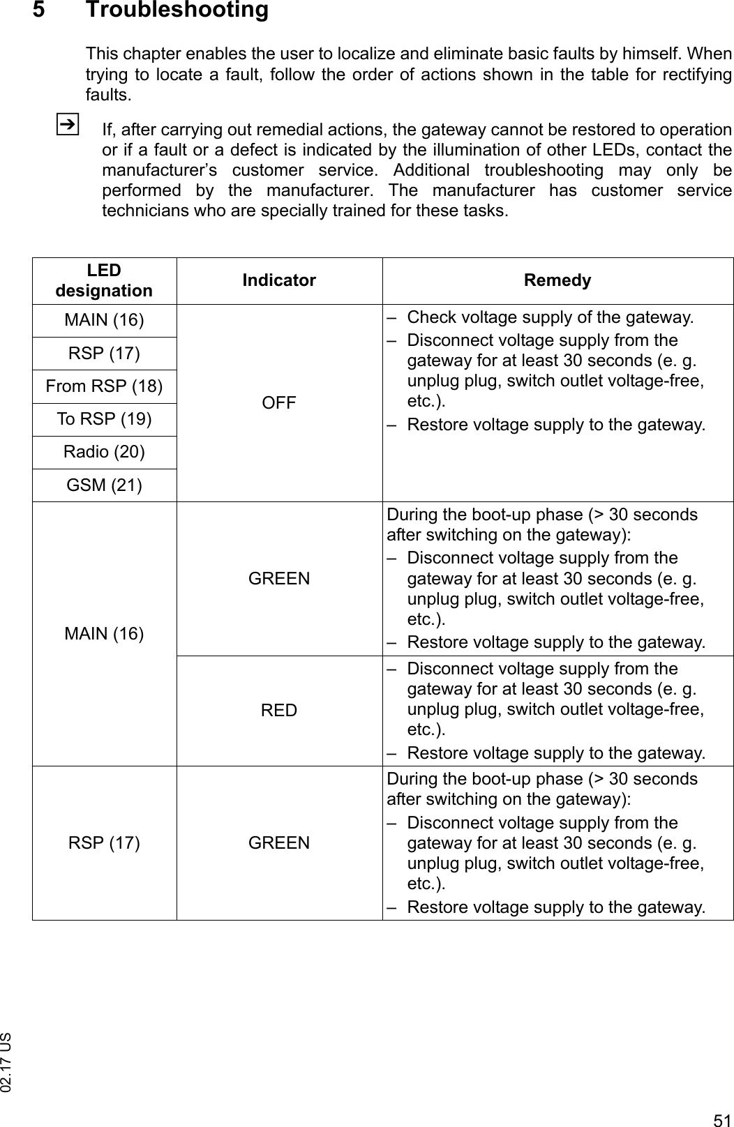
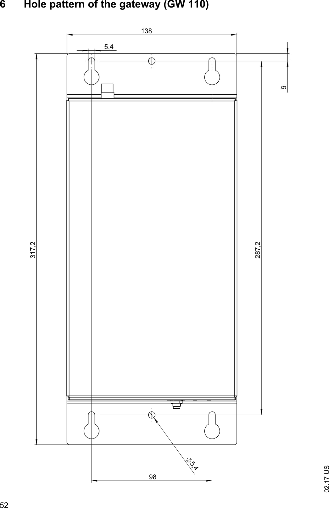
User Manual
Discussion / Help
Navigation