KAPSCH TRAFFICCOM CANADA 801154 Compact RF Module, model 801154 User Manual 288040
KAPSCH TRAFFICCOM CANADA INC. Compact RF Module, model 801154 288040
Contents
- 1. Installation instructions
- 2. Specifications
- 3. Revised user manual
- 4. Revised user manual containing RF exposure statement
- 5. revised installation instructed with corrected RF exposure statement
revised installation instructed with corrected RF exposure statement
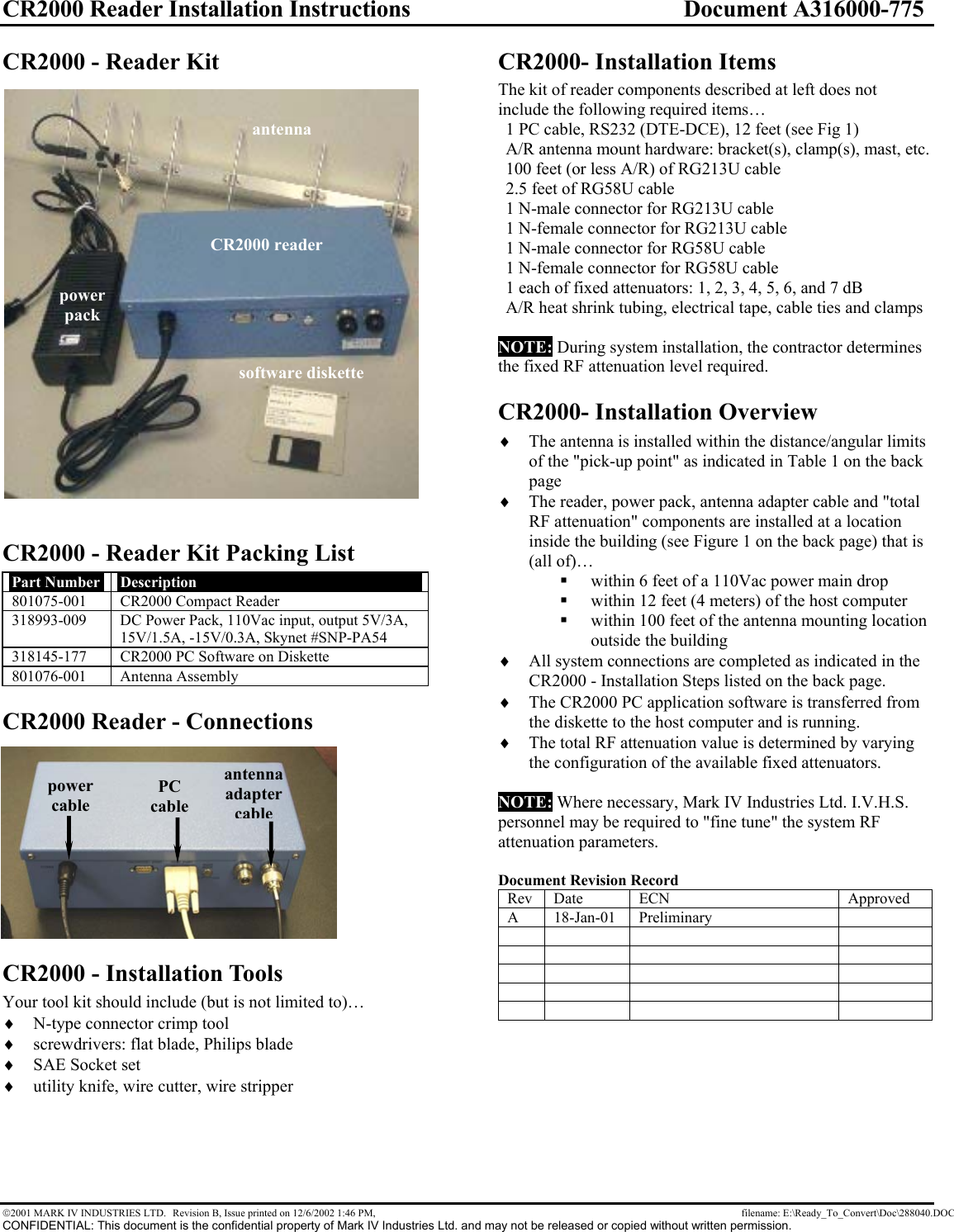
![CR2000 Reader Installation Instructions Document A316000-775 2001 MARK IV INDUSTRIES LTD. Revision B, Issue printed on 12/6/2002 1:46 PM, filename: E:\Ready_To_Convert\Doc\288040.DOC CONFIDENTIAL: This document is the confidential property of Mark IV Industries Ltd. and may not be released or copied without written permission. CR2000 - Antenna mounting The antenna will be mounted over-head at a height of Ha ft with horizontal polarization where Ha is measured from the highest part of the antenna. Determine the distance Do (in ft) between the "pick-up point" and the antenna mast, and use it to determine the antenna tilt down angle α° in the in-lane direction (H Plane), using the following table. Antenna Height (Ha) [ft] Pick-up Point (Do) * [ft] Antenna Tilt Angle (α) [Deg] Beam Center ** [ft] 12 5 to 7 15 3 7 to 9 18 4 12.5 5 to 7 15 3 7 to 9 18 4 13 6 to 8 15 3.5 8 to 10 18 4.5 13.5 7 to 9 15 4 9 to 10 18 4.5 * Distance referred to the antenna mast. ** Based on semi-empirical data. Note: User must maintain a separation distance of 23cm from the antenna. The antenna has gain of 6 db.CR2000 - Installation Steps Connect the antenna with the reader via RF feedline and RF attenuator(s) and antenna adapter cable. 1) Disconnect the power main input to the power supply. 2) Connect the Power supply output to the CR2000 reader. 3) Connect the PC port COM1 to the reader host port using the provided straight through RS-232 cable. 4) Connect the RF cable adapter (RG58 short cable) to the reader RF port (Type N connector). 5) Connect the RF feedline to the RF cable adapter via the fixed attenuator(s) referenced in step 9. Install a Type-N Male connector at the end of the feedline. 6) Route the RF feedline through the wall. At the feedline antenna end, slip 6" of heatshrink tubing on the cable. Install a Type-N female connector at the end of the feedline. Make the connection with the antenna. 7) Reconnect the power main input to the power supply. 8) Execute the CR2000 PC application software as referenced in document A316000-743. 9) Determine the "total RF attenuation" value by varying the configuration of the available fixed attenuator value(s). 10) After the system has been fully tested OK then heat shrink the tubing (in step 6) over the antenna connector to make it water tight. Figure 1 - Installation Diagramattenuator attenuatorN maleN maleN femaleN maleRF cableRG213U< 100 ftN female/femaleattenuator ***N maleN male/femaleantennaRF cableRG58U< 2.5 ftCR2000ReaderN femaleN male/femaleDCpowerpack110 VacmainssupplyHost PCrunningCR2000-PCsoftwareDB9 female Host port (P2)DB9 female*DCEDB9 maleDB9 male*RS232 cable#22AWG, 3 conductor> 6 ft < 40 ft (12 ft default or specify)Optional: RS485 cable#22AWG, 5 conductor> 40 ft < 200 ft (always specify)DTEvehicle with atransponder"RF capture zone"when RF is turned onoutside the buildinginside the building***total RF attenuation" valueis determined at the end ofthe installation processantenna adapter cableantenna feedline cable"total RF attenuation" value*Please verify the serial portconnector type on your hostPC, is it DB9 or DB25?PC cable](https://usermanual.wiki/KAPSCH-TRAFFICCOM-CANADA/801154.revised-installation-instructed-with-corrected-RF-exposure-statement/User-Guide-288040-Page-2.png)