KORTIDE R1 11N smart router User Manual M1
KORTIDE LIMITED 11N smart router M1
UserManual.wiki
>
KORTIDE
>
R1 User Manual
Users Manual
Navigation menu
Upload a User Manual
Namespaces
Wiki Guide
HTML
PDF
Info
Views
User Manual
Discussion / Help
Navigation
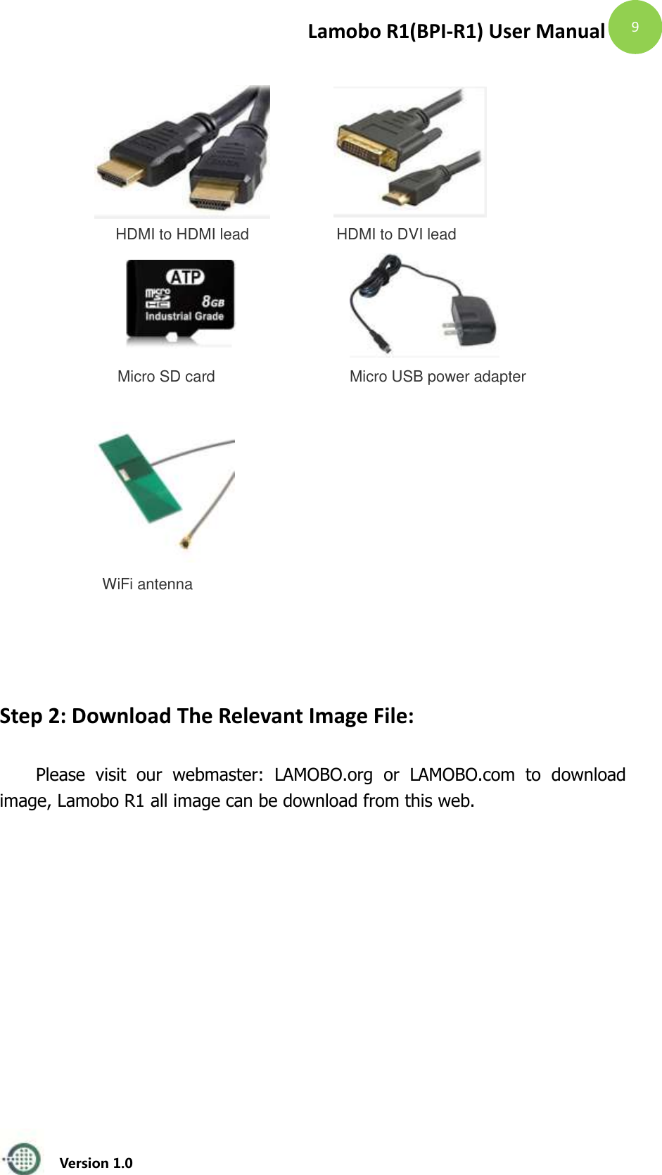
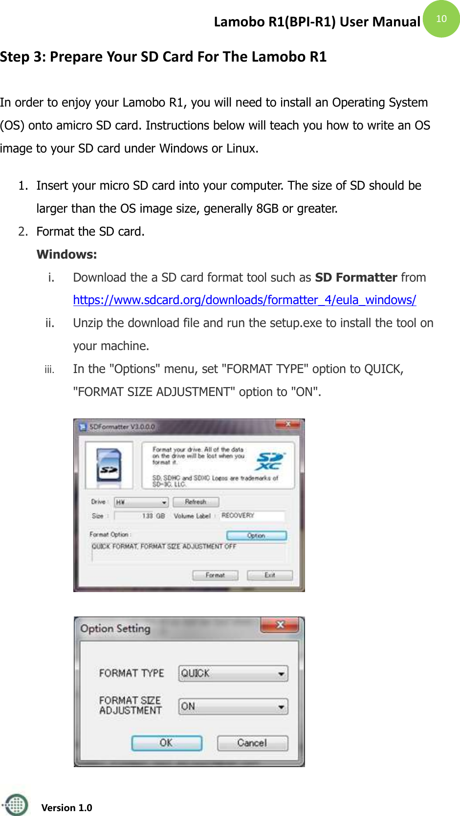
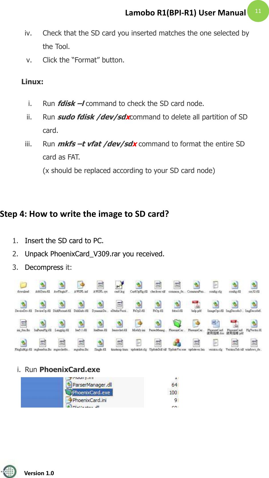
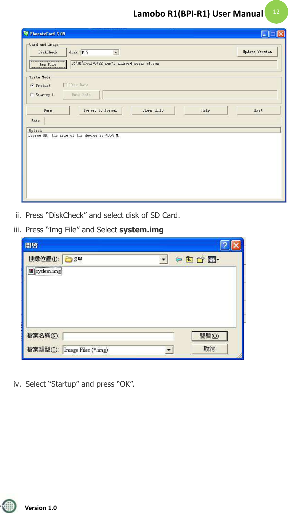
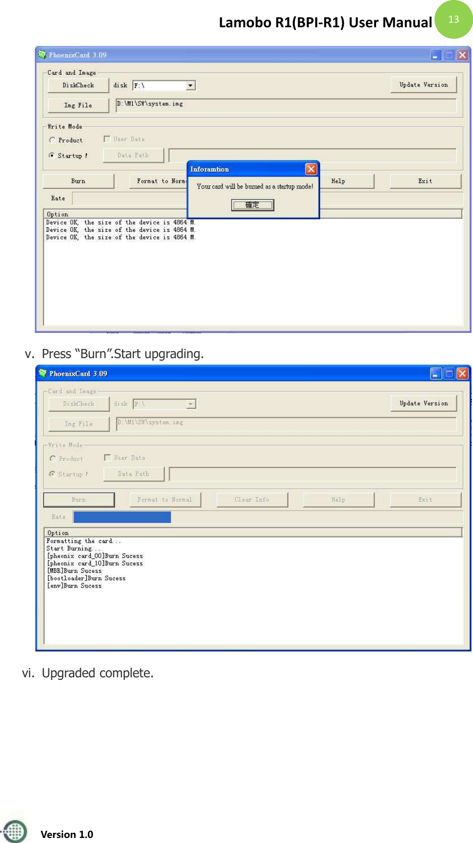
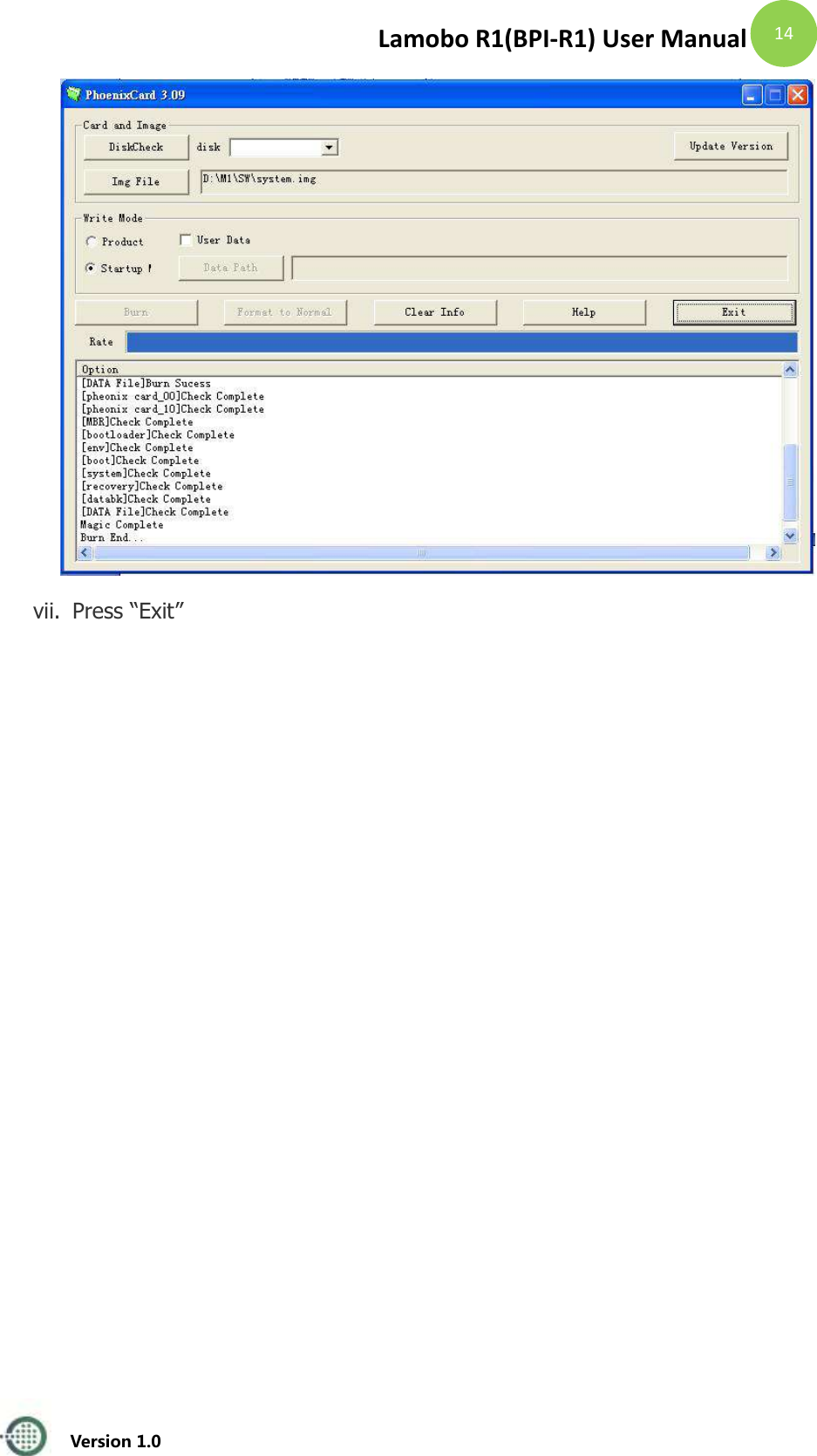
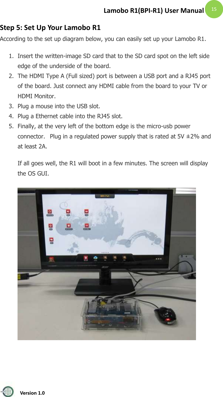

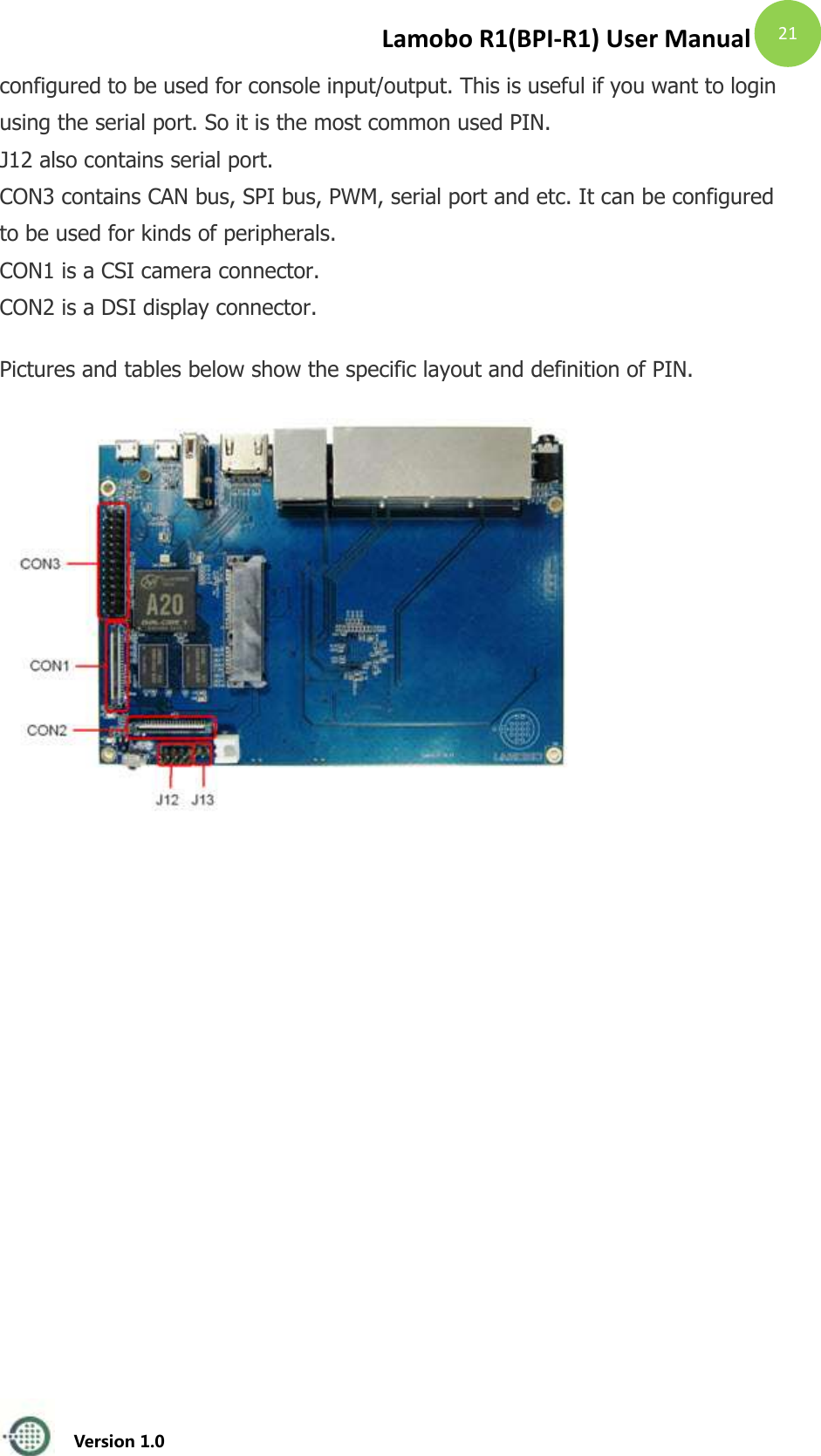
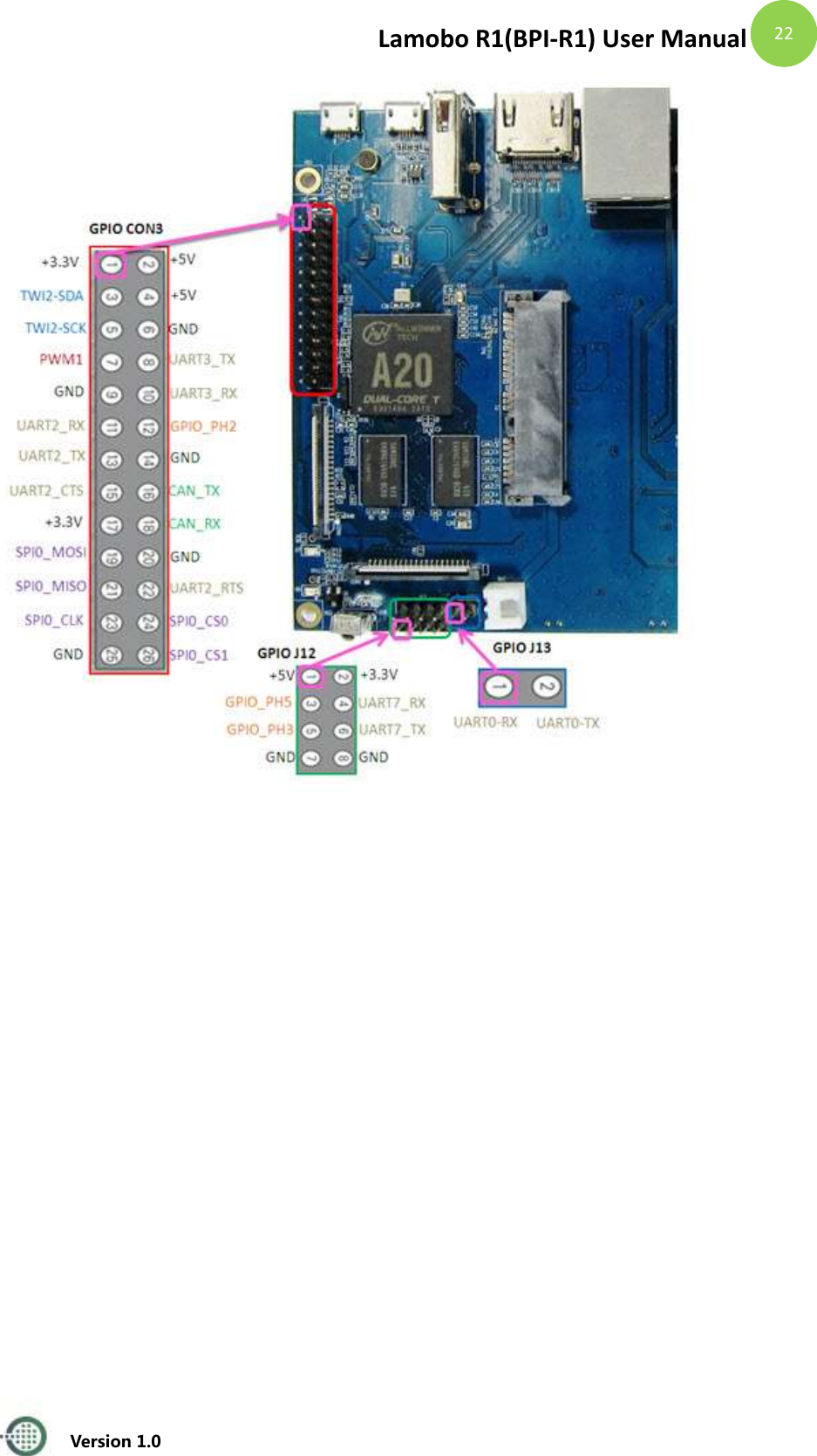
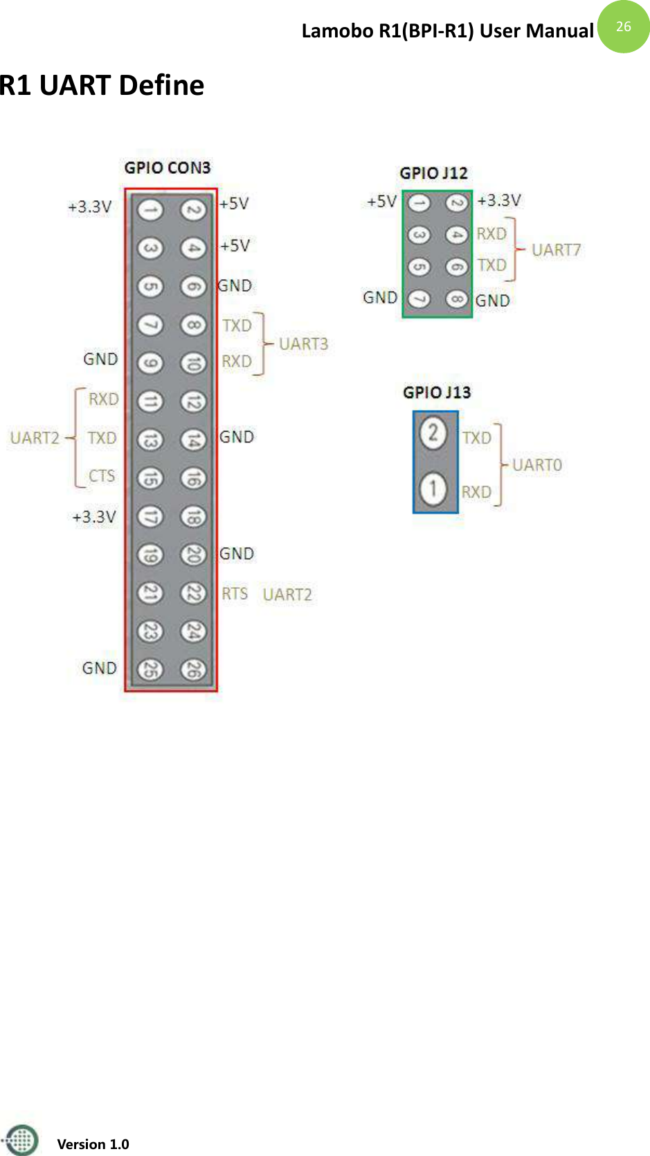
![Lamobo R1(BPI-R1) User Manual Version 1.0 20 Insert your micro-SD card into card reader. Write the OpenWrt image to the micro-SD card by using ‘sudo dd’: $ cd openwrt-lamobo-r1/bin/sunxi $ sudo dd if=openwrt-sunxi-Lamobo-R1-sdcard-vfat-ext4-configured.img of=/dev/sdX bs=10MB [Note]: “/dev/sdX” is the target micro-SD link in Linux host. Step 6: Set Up Your Lamobo R1 According to the set up diagram below, you can easily set up your Lamobo R1. 1. Insert the written-image SD card that to the SD card spot on the left side edge of the underside of the board. 2. Plug a mouse into the USB slot. 3. Plug an Ethernet cable into the RJ45 slot. 4. Finally, at the very left of the bottom edge is the micro-usb power connector. Plug in a regulated power supply that is rated at 5V ± 2% and at least 2A. If all goes well, the R1 will boot in a few minutes. Step 7: Shut Down Your Lamobo R1 This will shut down the PI safely, (just use the power key to turn off might damage the SD-cards file system). After that you can press the power key for 5 seconds to turn it off. GPIO Define We can check R1PINdefinition in this thread, including CON1, CON2, CON3, J12 and J13. J13 contains the default serial port UART0 (UART0-RX,UART0-TX). UATR0 is](https://usermanual.wiki/KORTIDE/R1/User-Guide-2528356-Page-21.png)