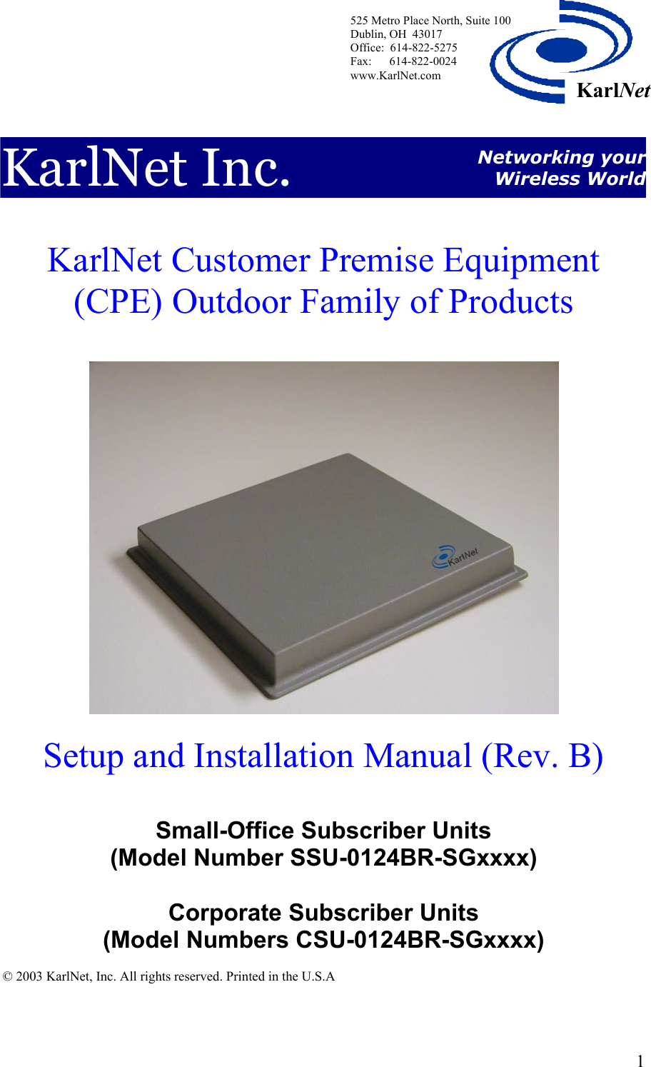
Karlnet 0003 802.11 Wireless Bridge User Manual 403286
Karlnet Inc. 802.11 Wireless Bridge 403286
UserManual.wiki
>
Karlnet
>
0003 User Manual
>
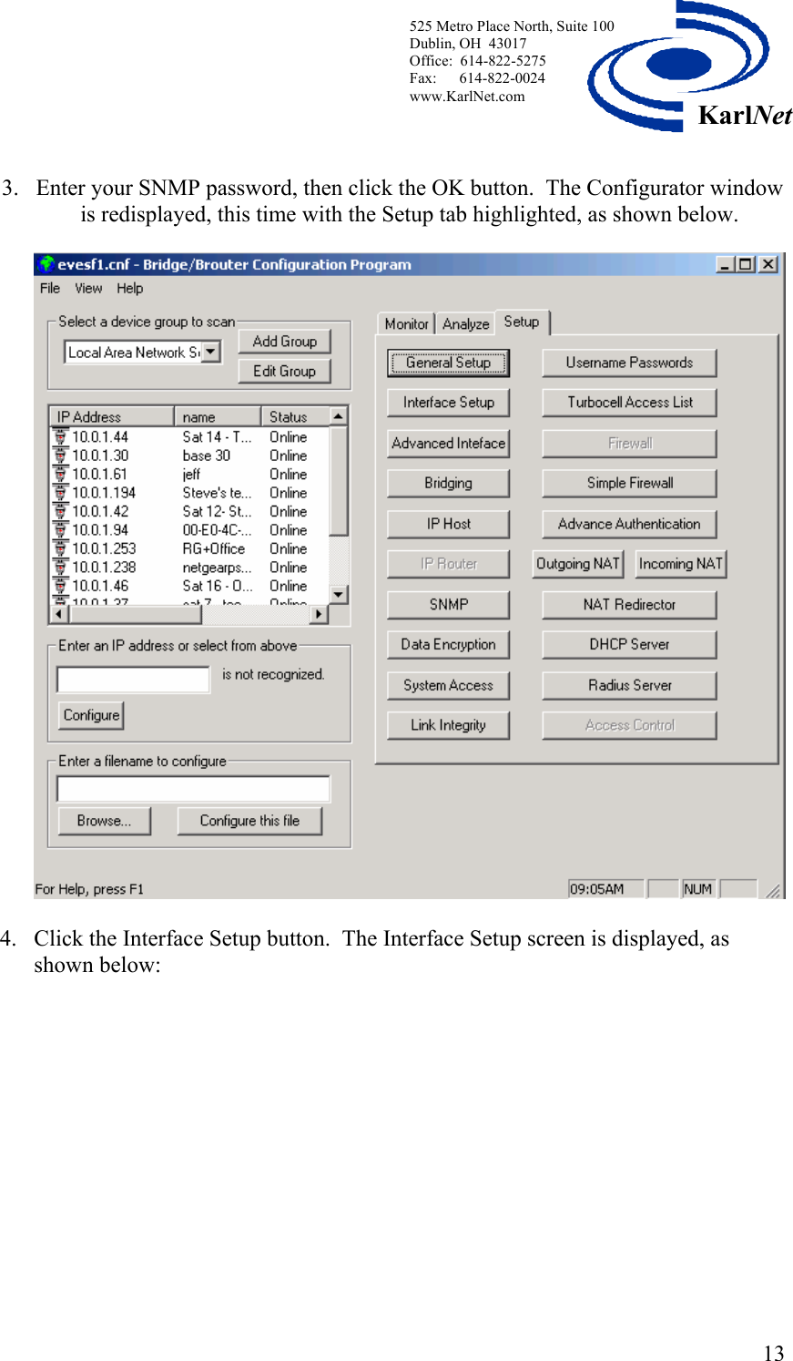
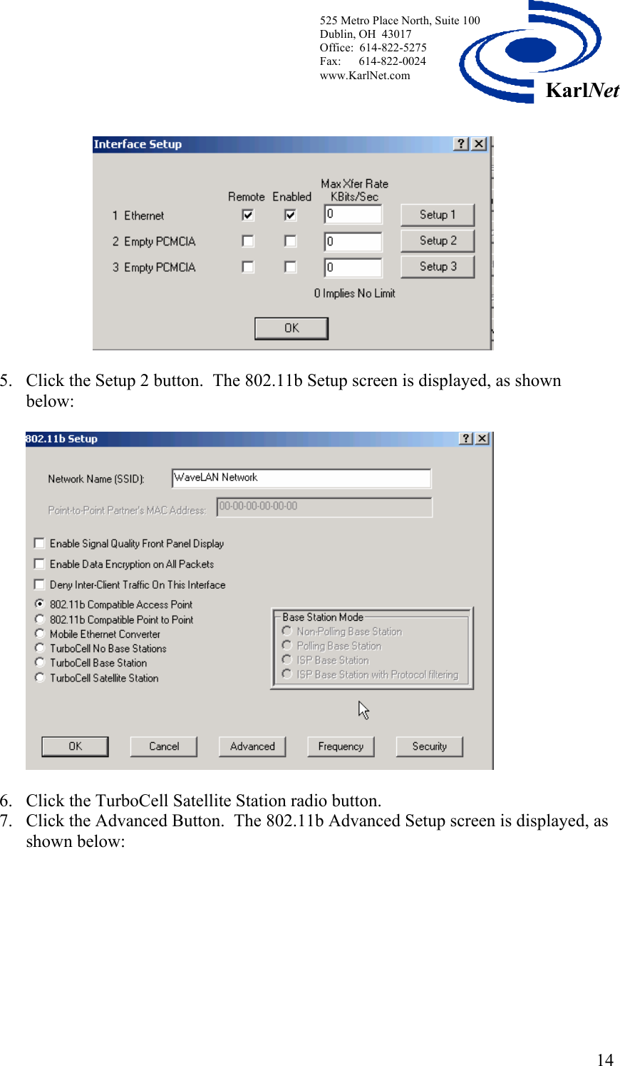
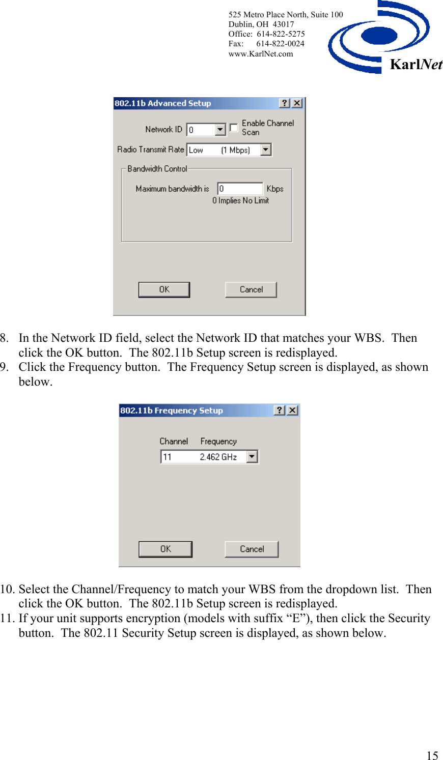
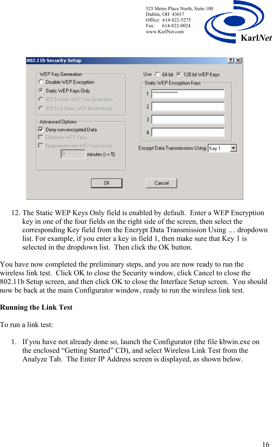
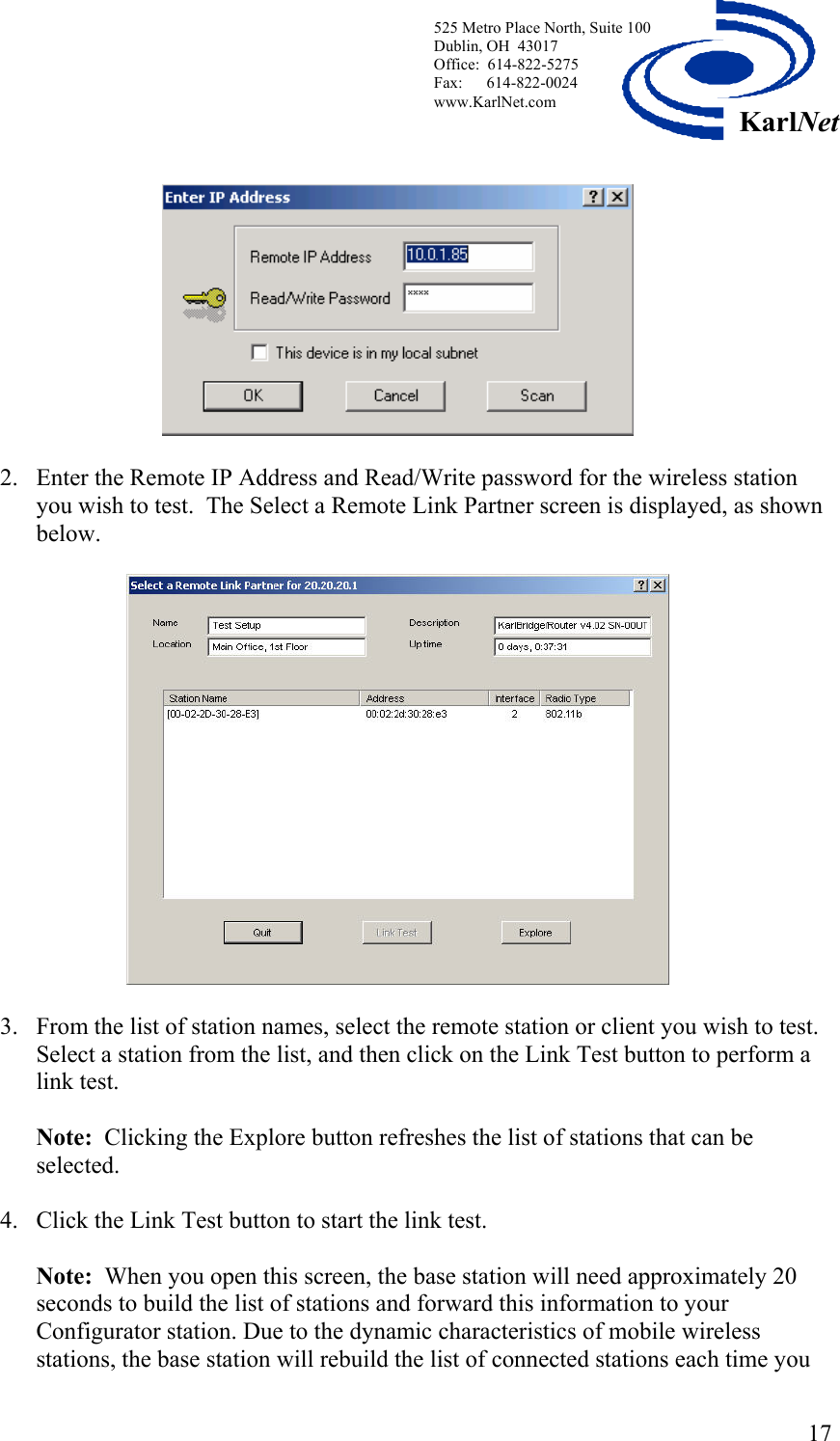
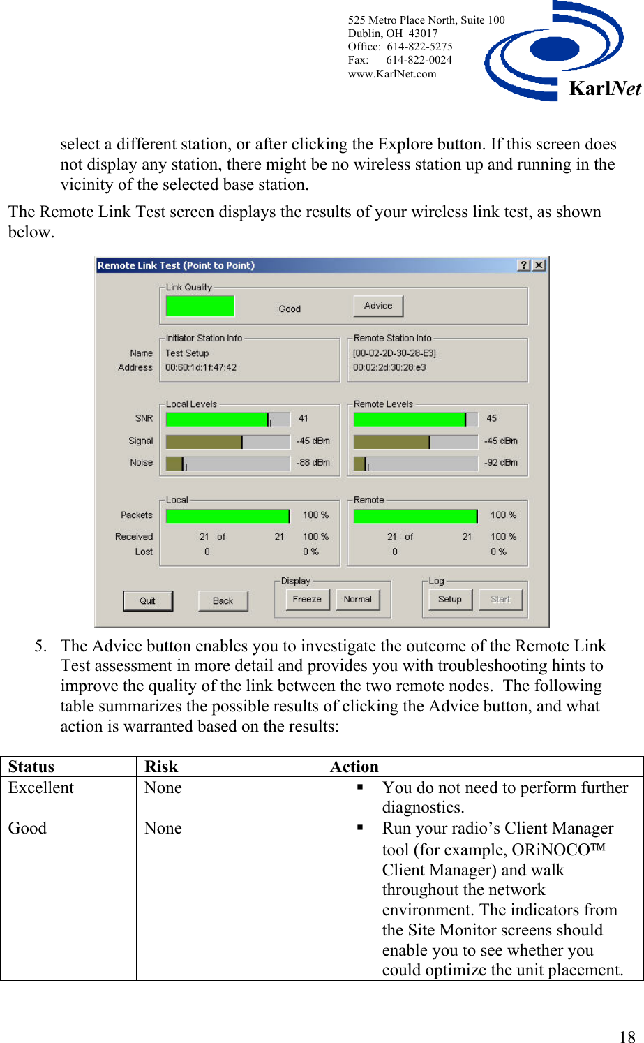
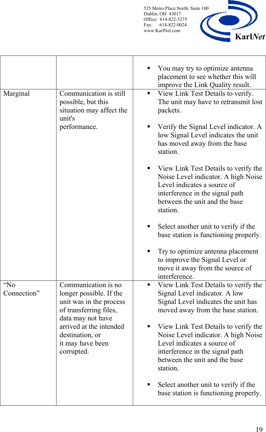
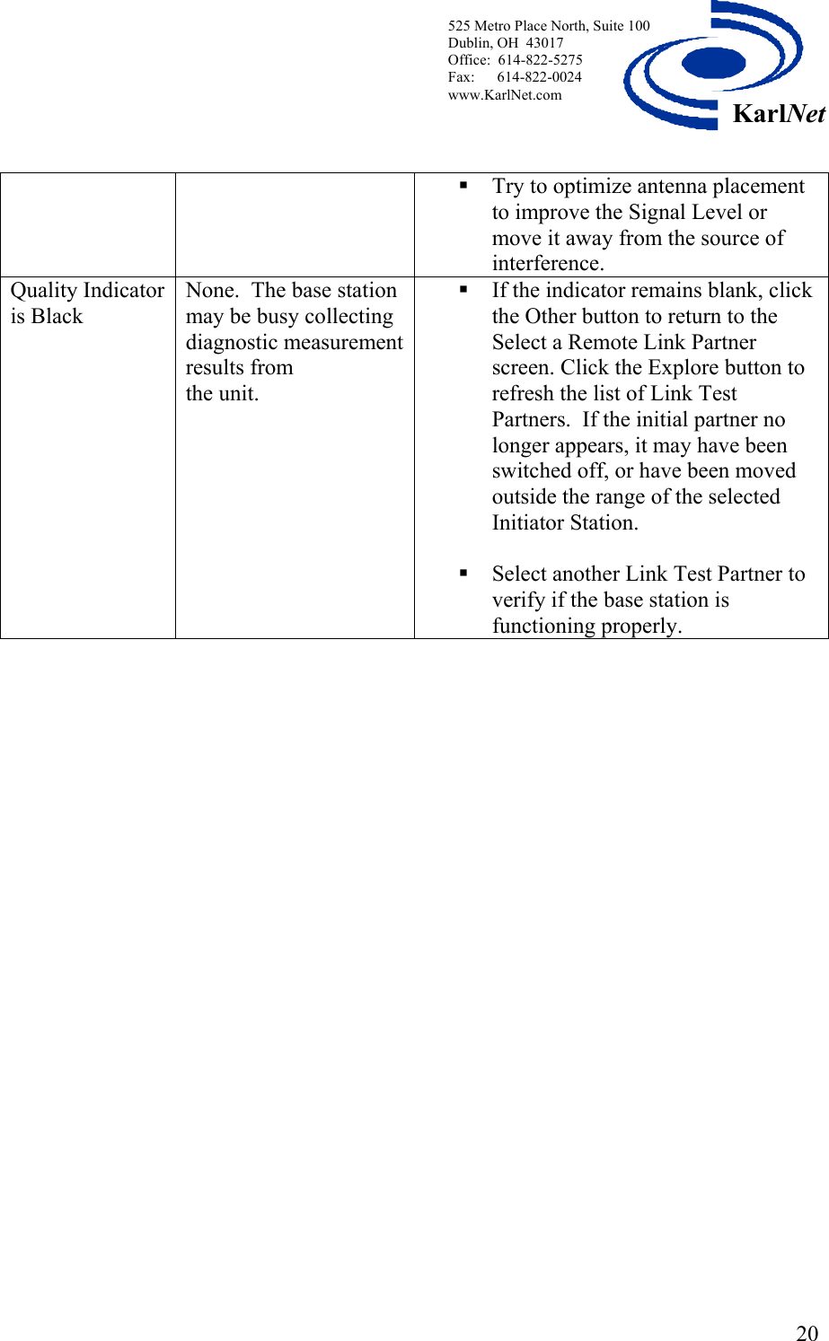
CSU Manual Revised
Contents
1.
CSU Manual Revised
2.
RSU Manual Revised
CSU Manual Revised
Navigation menu
Upload a User Manual
Namespaces
Wiki Guide
HTML
PDF
Info
Views
User Manual
Discussion / Help
Navigation