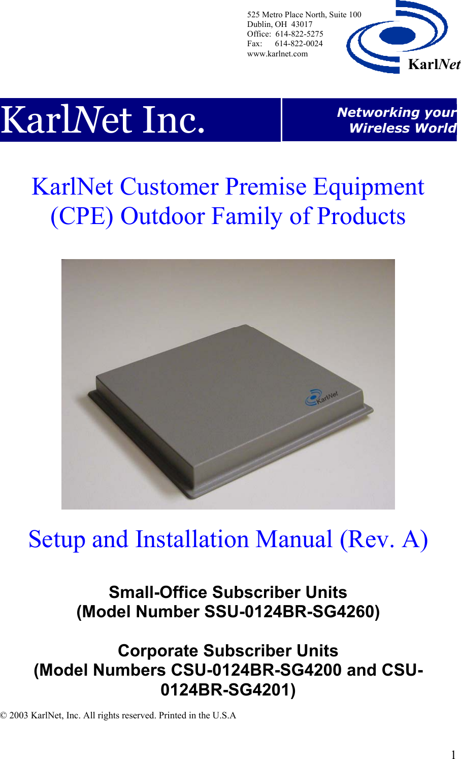
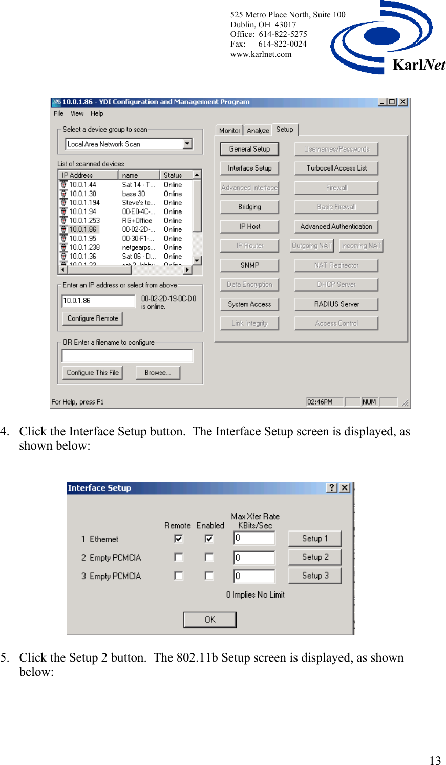
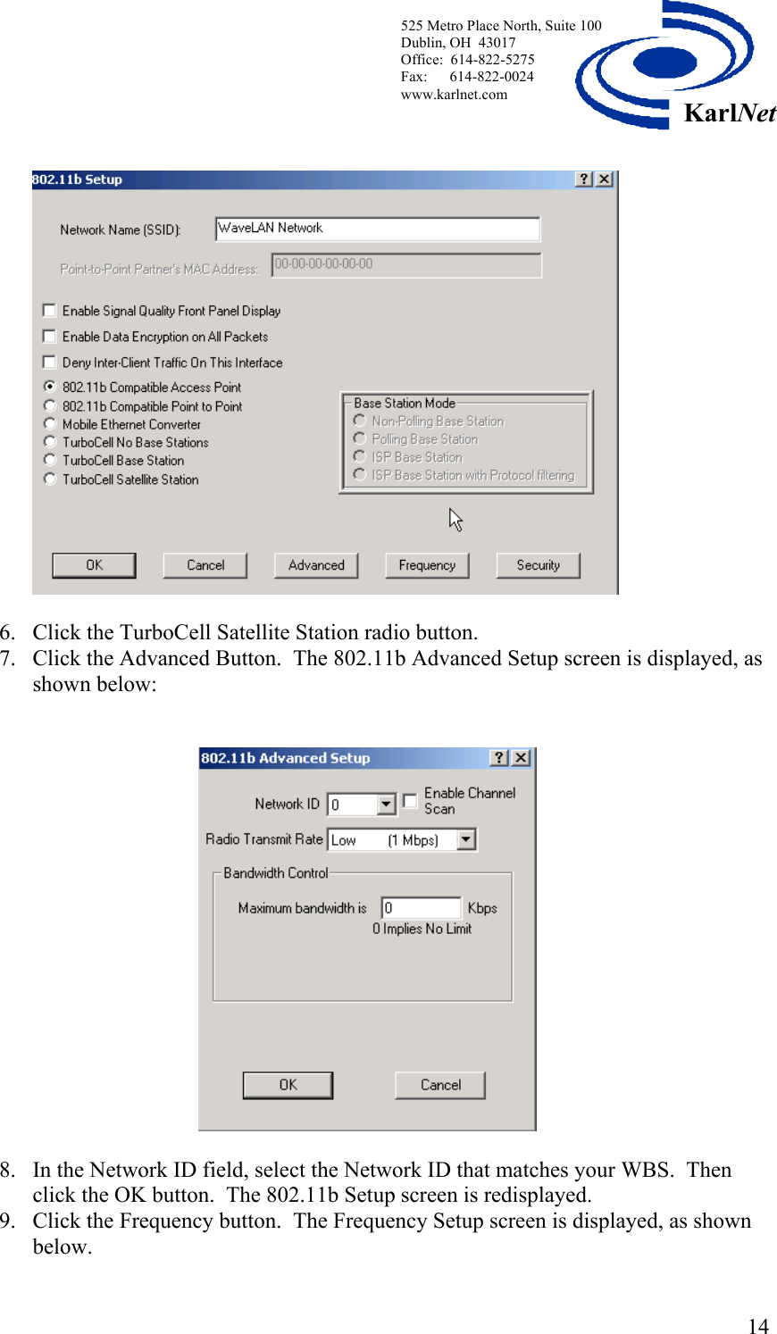
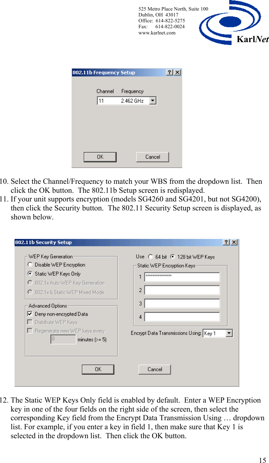
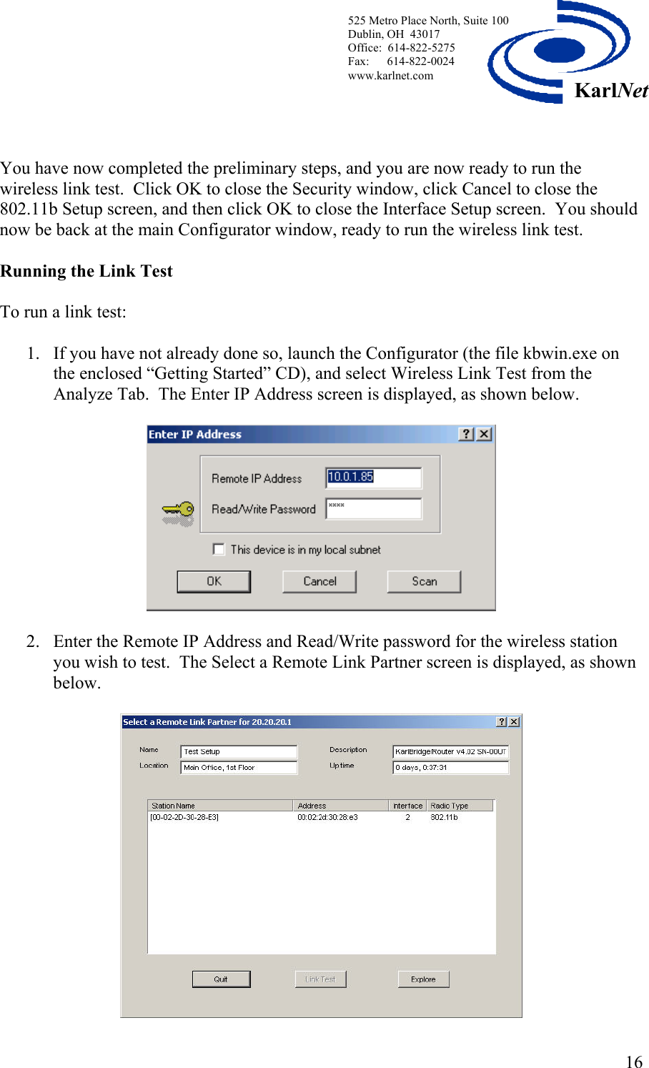
Karlnet KS-CPO010124B 802.11 Wireless Bridge User Manual KS CPO 0101 AVB Rxx Setup and Installation Manual
Karlnet Inc. 802.11 Wireless Bridge KS CPO 0101 AVB Rxx Setup and Installation Manual
UserManual.wiki
>
Karlnet
>
KS CPO010124B User Manual
Users Manual
Navigation menu
Upload a User Manual
Namespaces
Wiki Guide
HTML
PDF
Info
Views
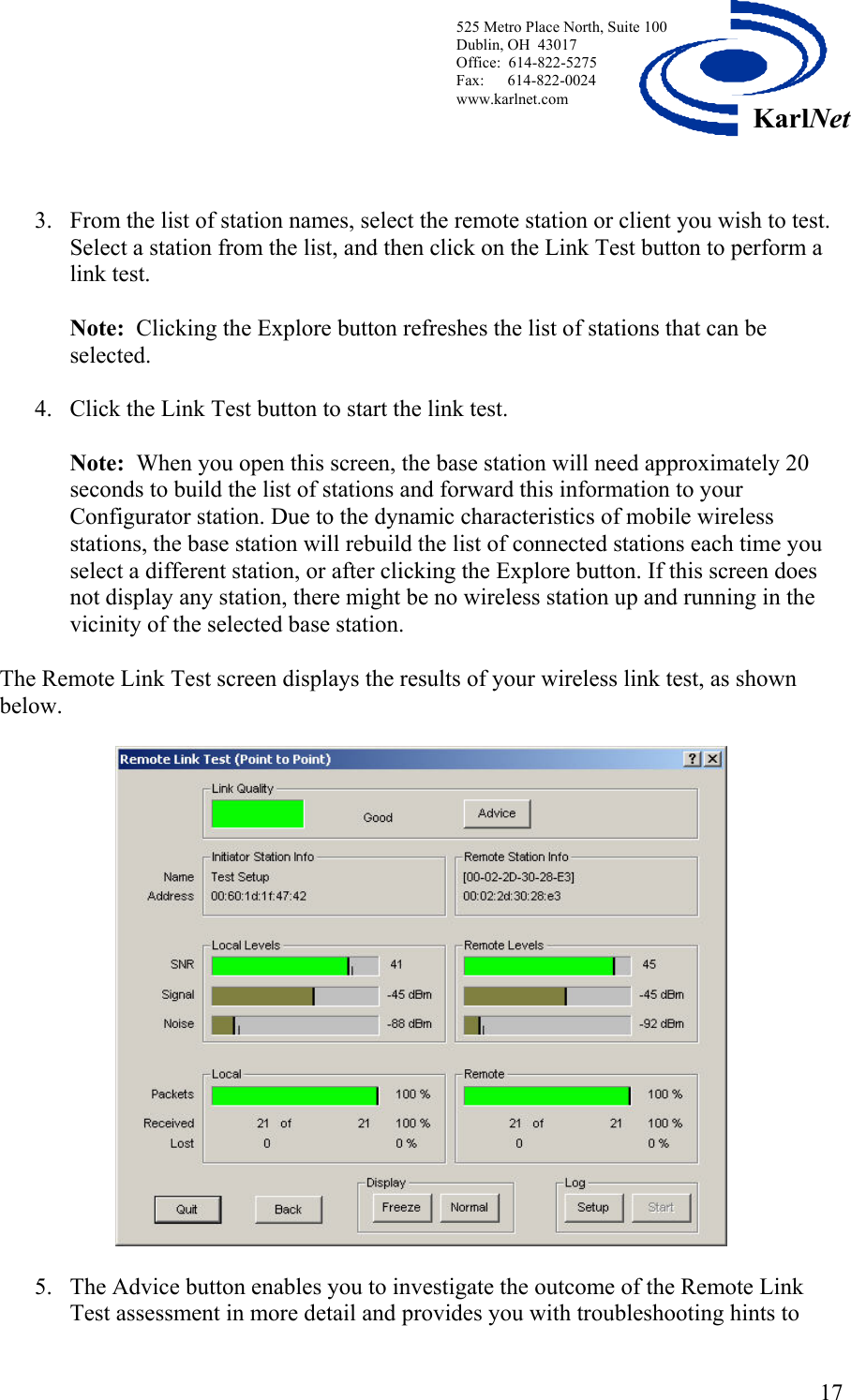
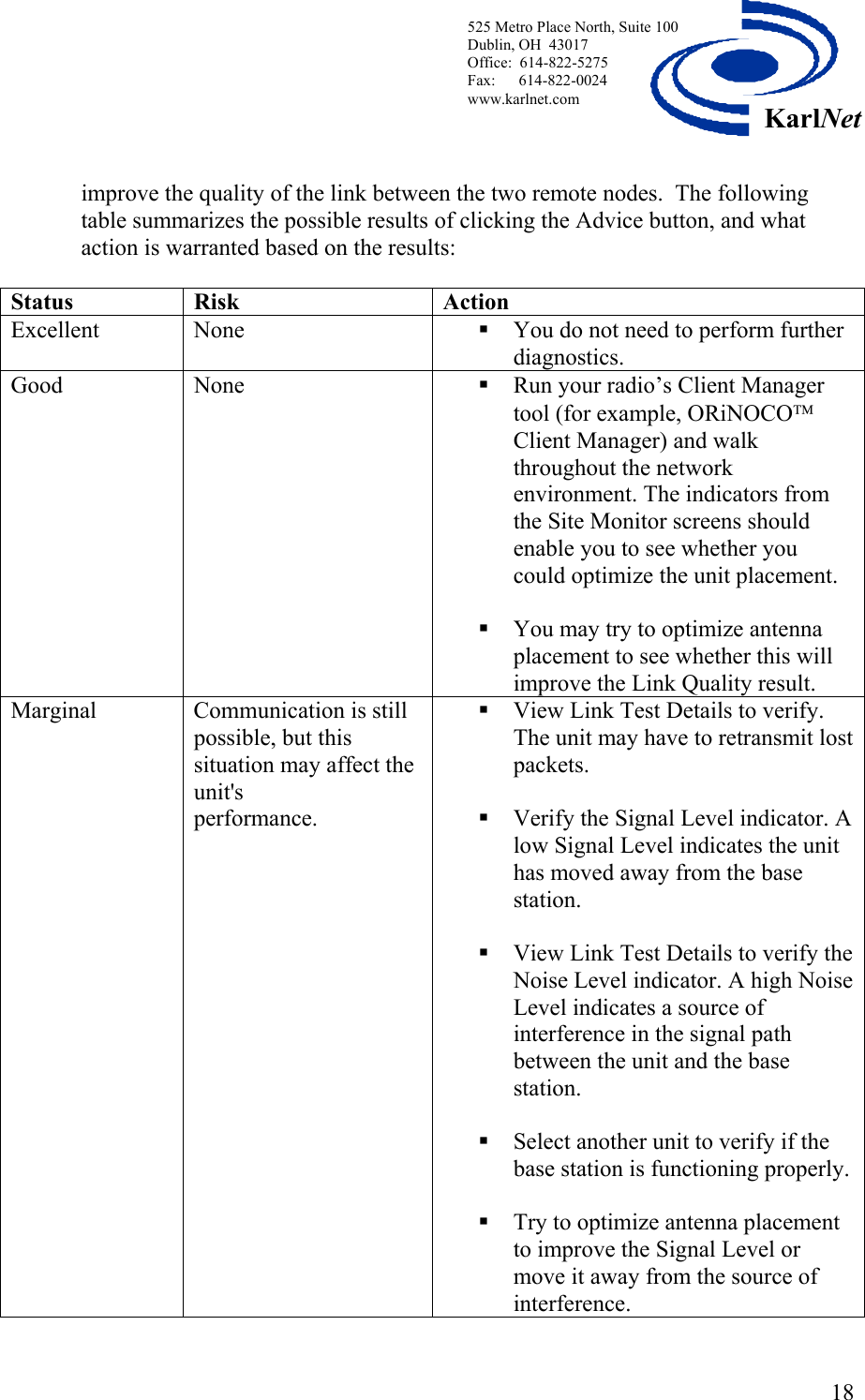
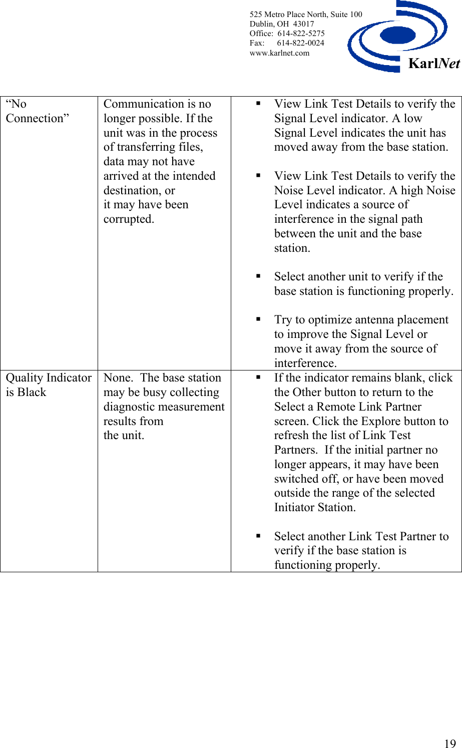
User Manual
Discussion / Help
Navigation