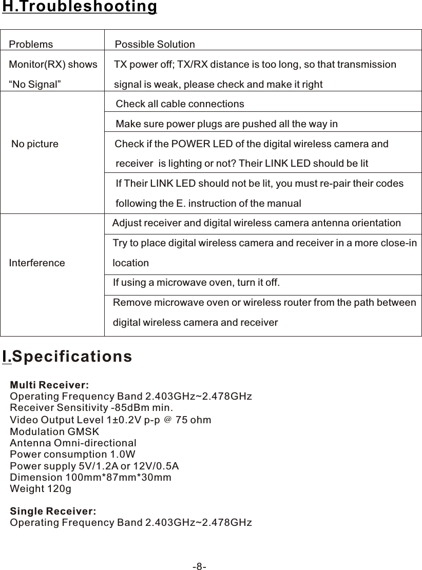
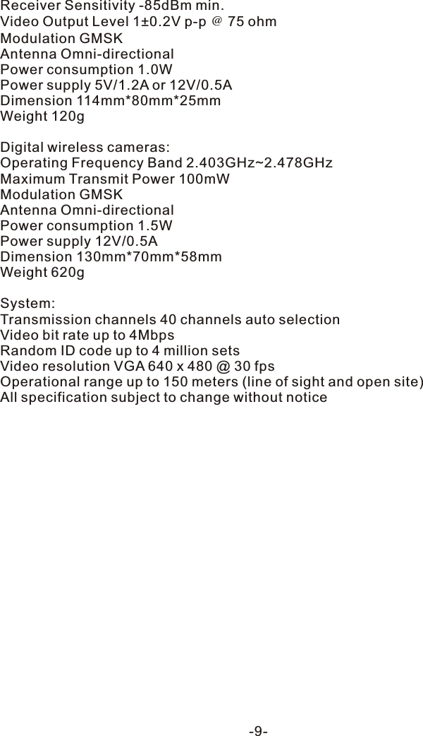
Kingwave Technology KW2430SA 2.4GHz Digital Transmission System User Manual KW2430S 2430 2431

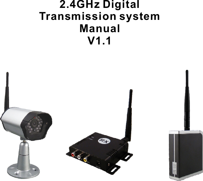
Kingwave Technology Co., Ltd. 2.4GHz Digital Transmission System KW2430S 2430 2431

User Manual

2.4GHz Digital Transmission system Manual V1.1
To prevent fire or shock hazard, do not expose this device to rain or moisture. Does not use near a bathtub, washbowl, kitchen sink, or laundry tub, in a wet basement, or near a swimming pool.►To avoid electrical shock, do not open this device.►This device should be operated to use only the power supply included with it or provided as an accessory.►Do not overload wall outlets and extension cords as this can result in the risk of fire or electrical shock.►Do not attempt to service this device yourself. Refer servicing to qualified personnel only.Reorient or relocate the receiving antenna.►Increase the separation between the equipment and receiver.►Connect the equipment into an outlet on a circuit different from that to which the receiver is connected.►Consult the dealer or an experienced radio/TV technician for help.■ Note:This equipment has been tested and found to comply with Part 15 of the FCC Rules, or R&TTE CE directive. These limits are designed to provide reasonable protection against harmful interference in a residential installation. This equipment generates, uses and can radiate radio frequency energy, if not installed and used in accordance with the instruction, it may cause harmful interference to radio communications. However, there is no guarantee that interference will not occur in a particular installation. If this equipment does cause harmful interference to radio or television reception, which can be determined by turning the equipment off and on, the user is encouraged to try to correct the interference by one or more of the following measures:Important-Safety PrecautionsNotice: The change or modifications not expressly approved by the party                responsible for compliance could void the user's authority to operate                the equipment.IMPORTANT NOTE: To comply with the FCC RF exposure compliance requirements,                                     no change to the antenna or the device is permitted. Any                                     change to the antenna or the device could result in the                                     device exceeding the RF exposure requirement and void                                     user's authority to operate the device.-1-
 -2-Please check the following items inside the box for 2.4Ghz Digital Video Transmission System, and contact your dealer if anything is missing:1. Products bodyA.What is inside the Box?andSingle Receiver x 1 4CH Multi Transmitter x 12. Accessory: for multi receiver or single receiver Refer to the following photo, from left to right:Antennas x 1 AV cables x 1(1RCA plug to 1RCA plug)Power Adaptor x 1(100V ~ 240V AC, DC 12V/0.5A or 5V/1.2A in Jack)4. This user manual3. Accessory for digital wireless cameraRefer to the following photo, from left to right:Antennas x 1Power Adaptor x 1(100V ~ 240V AC, DC 12V/0.5A in Jack)Bracket with screws x 3 or         Digital wireless camera x 1
-3-B.IntroductionThank you for purchasing this 2.4GHz Digital transmission system. This system is a digital wireless receiver/digital wireless CMOS camera that uses 2.4GHz Frequency Hopping technology and GMSK modulation, and each client has an ID for paring to protect personal privacy.Multiple receiver can get max. 4 pcs wireless cameras KW2431 to be quad display on one TV monitor, or connect to DVR BNC input.Single receiver can get only one. 1 pcs wireless cameras KW2431, and display on one TV monitor, or connect to DVR BNC input.There are over billion hopping sequences to minimize interference and deliver consistently an excellent video and audio quality up to 150 meters away(open site and line of sight)Using this 2.4GHz Digital Wireless system, you can enjoy greater convenience and security in many ways:Safety & Security Application: Connect a digital wireless camera as a wireless security system Monitor your sleeping baby, playing children, the elderly, or the disabled on TV by single or multiple receivers See who is outside the door on TV through digital wireless CMOS camera.Monitors and records the meeting from another room.IMPORTANT NOTE: To comply with the FCC RF exposure compliance requirements, the antenna(s) used for this transmitter must be installed to provide a separation distance of at least 20 cm from all persons and must not be co-located or operating in conjunction with any other antenna or transmitter. No change to the antenna or the device is permitted. Any change to the antenna or the device could result in the device exceeding the RF exposure requirements and void user’s authority to operate the device.
-4-DC Jack for power adaptorDC Jack for power adaptorPower LEDAV Jack for Output(RX) AntennaPairing buttonsPower LED AntennaC.Product LayoutFront ViewBack ViewAntenna ConnectorFor digital wireless camera  Front view Back view Pairing button insideAV Jack for output(RX)MODEPAIR CH
-5-D. Multiple ReceiverTV monitor1 x RCA (Video) cablesDC 12V or 5V InputVideo Out(4CH)Multi ReceiverSingle Receiver TV Monitor1 x RCA (Video) cableDC 12 or 5V InputDVRVideo Out
-6-E.Pairing the digital wireless camera and receiversWhen you get the digital wireless cameras or receiver, you must pair them before use it, following the instructions as below:1.Power on the digital wireless camera and receiver by inserting the power adaptor jack.2.Press the PAIR/CH or PAIR button of receivers and not release until the power LED begin to flash, and the monitor will reveal the picture as below, then release the PAIR/CH button.3.Press the PAIR button of digital wireless camera once within 30 seconds . They will automatically link to each other by ID code after pairing finished.4.Please don't turn off their power during the paring status.5.When pairing successfully, the power LED for both will be lit directly (not flash) Pairing buttonPairing button
-7-F.:Operations1.Multiple receiver:long press PAIR/CH button will get into paring mode as E; press PAIR/CH button shortly to switch the display as CAM1 → CAM2 → CAM3 → CAM4 → Quad mode → CAM1…… sequentially by each pressing.2.Single receiver:long press PAIR button will get into paring mode as E; press PAIR button shortly to switch OSD on/off.3.Multiple receiver:long press MODE button to get into SCAN mode, it will display CAM1 → CAM2 → CAM3 → CAM4 → CAM1…… automatically every 5 seconds, and press PAIR/CH button to stop; press MODE button shortly to switch OSD on/off.4. Multiple receiver:long press PAIR/CH and MODE buttons until show up“Erase All Pairing Data” , it will clear the pairing content ,so that it would be quick when you repairG.Use Notes1.Be sure the digital wireless camera and the receiver were connected to the    equipment correctly (e.g. Connect the digital wireless camera, and the receiver to    the TV or DVR).2.When DC plug is pulled out from digital wireless camera or receiver, it needs to wait    for a few seconds to insert it again.3.Adjust antenna to decrease interference. (vertical or horizontal)4.In most situations, one pair has a better distance up to 150 meter(open site and line    of sight). When two pairs or more are used at the same time, it can automatically jump    to different channels. But the distance between pairs, preferably greater than 2 meter far.5.If there are some reasons cause the devise stop, you can try to pull out and insert the    power plug again and make the devise re-link.6.It is suggested to have 10 pairs mostly operated in same location, but the pairing can    not be at the same time.
-8-Problems                      Possible SolutionMonitor(RX) shows      TX power off; TX/RX distance is too long, so that transmission“No Signal”                   signal is weak, please check and make it right                                        Check all cable connections                                                                               Make sure power plugs are pushed all the way in No picture                    Check if the POWER LED of the digital wireless camera and                                       receiver  is lighting or not? Their LINK LED should be lit                                      If Their LINK LED should not be lit, you must re-pair their codes                                      following the E. instruction of the manual                                      Adjust receiver and digital wireless camera antenna orientation                                     Try to place digital wireless camera and receiver in a more close-in Interference                 location                                     If using a microwave oven, turn it off.                                     Remove microwave oven or wireless router from the path between                                      digital wireless camera and receiverH.TroubleshootingMulti Receiver:Operating Frequency Band 2.403GHz~2.478GHzReceiver Sensitivity -85dBm min.Video Output Level 1±0.2V p-p @ 75 ohmModulation GMSKAntenna Omni-directionalPower consumption 1.0WPower supply 5V/1.2A or 12V/0.5ADimension 100mm*87mm*30mmWeight 120gSingle Receiver:Operating Frequency Band 2.403GHz~2.478GHzI.Specifications
Receiver Sensitivity -85dBm min.Video Output Level 1±0.2V p-p @ 75 ohmModulation GMSKAntenna Omni-directionalPower consumption 1.0WPower supply 5V/1.2A or 12V/0.5ADimension 114mm*80mm*25mmWeight 120gDigital wireless cameras:Operating Frequency Band 2.403GHz~2.478GHzMaximum Transmit Power 100mWModulation GMSKAntenna Omni-directionalPower consumption 1.5WPower supply 12V/0.5ADimension 130mm*70mm*58mmWeight 620gSystem:Transmission channels 40 channels auto selectionVideo bit rate up to 4MbpsRandom ID code up to 4 million setsVideo resolution VGA 640 x 480 @ 30 fps Operational range up to 150 meters (line of sight and open site)All specification subject to change without notice-9-

Navigation menu