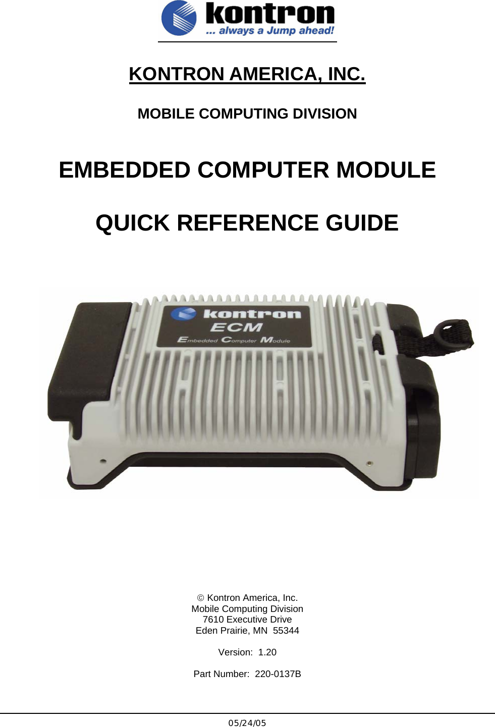
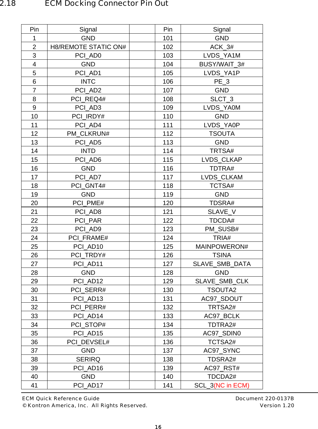
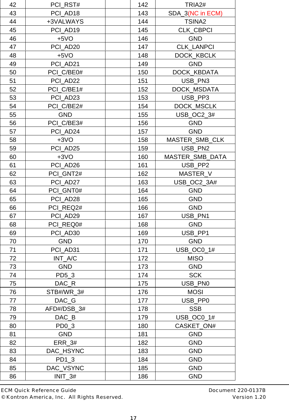
Kontron America ECM1400 ECM1400 Embedded Computer Module User Manual Manual

Kontron America Inc. ECM1400 Embedded Computer Module Manual

Manual

 05/24/05 KONTRON AMERICA, INC. MOBILE COMPUTING DIVISION  EMBEDDED COMPUTER MODULE   QUICK REFERENCE GUIDE            © Kontron America, Inc.  Mobile Computing Division 7610 Executive Drive  Eden Prairie, MN  55344  Version:  1.20  Part Number:  220-0137B
 ECM Quick Reference Guide     Document 220-0137B © Kontron America, Inc.  All Rights Reserved.    Version 1.20         i  Table of Contents EMBEDDED COMPUTER MODULE 1.0 DOCUMENT REVISION HISTORY ..................................................................................................3 2.0 USER INFORMATION ......................................................................................................................3 2.1 Objective.........................................................................................................................................3 2.2 Assumptions ...................................................................................................................................3 2.3 Scope..............................................................................................................................................3 2.4 About This Manual..........................................................................................................................5 2.5 Copyright Notice.............................................................................................................................5 2.6 Symbols Used In This Manual........................................................................................................5 2.7 Safety Instructions ..........................................................................................................................6 2.8 Safety Instructions for the CMOS Lithium Battery..........................................................................7 2.9 FCC Statement...............................................................................................................................7 2.10 Care and Maintenance ...................................................................................................................8 2.11 Warranty .........................................................................................................................................9 2.12 Technical Support.........................................................................................................................10 2.13 Returning Defective Merchandise ................................................................................................10 3.0 BASIC SPECIFICATIONS, ENVIROMENTALS AND CERTIFICATIONS ....................................12 3.1 SPECIFICATIONS........................................................................................................................12 3.2 Environmental Specifications .......................................................................................................13 3.3 Certifications.................................................................................................................................14 3.4 ECM Docking Connector Schematic ............................................................................................15 3.5 ECM Docking Connector Pin Out.................................................................................................16 4.0 Removable Hard Drive Module ....................................................................................................18 4.1 Description....................................................................................................................................18 5.0 BIOS................................................................................................................................................18
 ECM Quick Reference Guide     Document 220-0137B © Kontron America, Inc.  All Rights Reserved.    Version 1.20         ii  6.0 Embedded Controller....................................................................................................................18 7.0 Operating Systems........................................................................................................................18 8.0 Dynamic Speed Stepping .............................................................................................................19
 ECM Quick Reference Guide     Document 220-0137B © Kontron America, Inc.  All Rights Reserved.    Version 1.20         3  Embedded Computer Module   1.0 DOCUMENT REVISION HISTORY Revision  Date  Edited By  Changes from last revision 0.10 12/07/2004 GMA  Initial Draft. 0.20 01/14/2004 GMA  Feedback updates. 0.90  02/17/2004  GMA  Pre-release review and updates. 1.20 05/23/05 CSF  Release Updates  2.0 USER INFORMATION 2.1 Objective  This document is intended to give basic definition of the Kontron Embedded Computer Module (ECM) base computer.  The base computer alone is not a functional device and requires a docking station designed to interface with the ECM in order for it to become functional.  Depending on desired I/O and degree of ruggedness required for the End Users application, Kontron America—Mobile Computing Division can either supply a Development Kit for End Users to design their own interfaces or Kontron can customize a dock. For a technical reference guide of the Kontron Development Docking Stations, please refer to the CD utilities disk (P/N 224-0078).  2.2 Assumptions  The reader is assumed to have already designed, or is using a Kontron America—Mobile Computing Division pre-designed docking station to run their application.   2.3 Scope  The information presented in this guide is basic to the ECM and simply covers the pin-out of the docking connector, the level of certification obtained and the MIL-STD testing performed on the ECM only.  Customers designing their own interfaces to the ECM are responsible for meeting required certification and testing using the ECM and their own specific docking devices.   Depending on required certification and/or testing, the application circuits use in the ECM may not be suitable for all applications.  In particular, additional components may need to be added to these circuits in order to
 ECM Quick Reference Guide     Document 220-0137B © Kontron America, Inc.  All Rights Reserved.    Version 1.20         4  meet specific EMI/EMC, or safety isolation requirements.  Such regulatory requirements and the techniques for meeting them vary by industry and are beyond the scope of this document.
 ECM Quick Reference Guide     Document 220-0137B © Kontron America, Inc.  All Rights Reserved.    Version 1.20         5   2.4 About This Manual  This document provides information about products from Kontron America—Mobile Computing Division.  No warranty of suitability, purpose, or fitness is implied.  While every attempt has been made to ensure that the information in this document is accurate, the information contained within this document is supplied “as-is” and can change without notice. For the circuits, descriptions and tables indicated, Kontron America—Mobile Computing Division assumes no responsibility as far as patents or rights of third parties are concerned.   2.5 Copyright Notice  Copyright © 2005 Kontron America, Inc.  All rights reserved.  No part of this manual may be reproduced, transmitted, transcribed, stored in a retrieval system, or translated into any language or computer language, in any form or by any means (electronic, mechanical, photocopying, recording, or otherwise), without the express written permission of Kontron America—Mobile Computing Division. 2.6 Symbols Used In This Manual   Symbol Meaning   This symbol indicates the danger of injury to the user or the risk of damage to the product if the corresponding warning notices are not observed.  This symbol indicates that the product or parts that may be damaged if the corresponding warning notices are not observed.   ®  Windows, Windows XP Professional, Windows 2000 Professional and MS-DOS, are registered trademarks of the Microsoft Corporation. ®  IBM, PC-AT, OS/2 and PS/2 are registered trademarks of the International Business Machines Corporation. ®  Intel and Pentium are registered trademarks of Intel Corporation. ®  UNIX is a registered trademark and exclusively licensed from the X/Open Company Limited. ®  LINUX is a registered trademark and exclusively licensed by Linus Torvalds ®  Solaris is a registered trademark of Sun Microsystems, Inc.  Other product names cited in this manual may also be trademarks and are used here solely for identification purposes.
 ECM Quick Reference Guide     Document 220-0137B © Kontron America, Inc.  All Rights Reserved.    Version 1.20         6    2.7 Safety Instructions   Please read this section carefully and observe the following instructions – and those on the computer - for your own safety and correct use of the ECM.  Kontron built and tested the ECM computer in accordance with EN60950. In order to maintain this condition and ensure safe operation, you must observe the instructions and warnings contained here and elsewhere in this manual.   Do not operate an ECM with wireless capability in areas sensitive to radio interference, such as airplanes and hospitals without turning these devices off using Windows O/S functions.   For Operating Systems other than Windows, turn the system off to stop transmitting.   •  Operate the ECM in accordance with the instructions for use. •  Make sure electrical receptacles match the regulations in your area. •  Place cables, especially the power cable, out of traffic areas where people could trip over them. •  Do not put an AC power connection in sockets shared by a number of other power users.  •  Do not use an extension cable. •  Plug the power cable into a nearby socket to prevent an accidental disconnection. •  Use only the cables supplied by Kontron. •  Do not place the ECM in the proximity of heat sources or in a damp location. Make sure it has adequate ventilation. •  Connect to ECM interface: only devices and components that meet the requirements of a SELV circuit (security low voltage output) in accordance with EN60950.  •  Lock or screw down all plugs on the connection cables to the housing. •  You may not safely operate the ECM if:  –it has visible damage or –it no longer functions. Shut down the computer and secure it against unintentional operation.  •  Any extensions to the computer must meet legal stipulations and the device specifications.  •  Only authorized Kontron technical repair personnel may perform assembly, extensions, new settings, alterations or repairs while under warranty. •  Only use original accessories approved by Kontron.
 ECM Quick Reference Guide     Document 220-0137B © Kontron America, Inc.  All Rights Reserved.    Version 1.20         7    2.8 Safety Instructions for the CMOS Lithium Battery   The CPU board is equipped with an internal, rechargeable CMOS lithium battery. Please refer to the “Technical Data” section for information about battery type. •  This battery is not user-replaceable. •  Kontron shall not assume any warranty obligation if any attempt is made to replace the battery by individuals other than those at Kontron repair facilities. •  Please observe local regulations for the disposal of the battery and the disposal information of the battery-manufacturers.  2.9 FCC Statement    Note: This equipment has been tested and found to comply with the limits for a Class A digital device, pursuant to part 15 of the FCC Rules.  These limits are designed to provide reasonable protection against harmful interference when the equipment is operated in a commercial environment.  This equipment generates, uses, and can radiate radio frequency energy and, if not installed and used in accordance with the instruction manual, may cause harmful interference to radio communications.  Operation of this equipment in a residential area is likely to cause harmful interference in which case the user will be required to correct the interference at his own expense.   CANADIAN NOTICE  This digital apparatus does not exceed the Class A limits for radio noise for digital apparatus set out in the Radio Interference Regulations of the Canadian Department of Communications.  EUROPEAN UNION NOTICE Warning: This is a Class A product. In a domestic environment this product may cause radio interference in which case the user may be required to take adequate measures to mitigate such interference.  CAUTION Danger of explosion if battery is incorrectly replaced. Replace only with the same or equivalent type recommended by the manufacturer. Dispose of used batteries according to the manufacturer’s instructions.  WARNING  Only authorized service personnel should attempt to repair this equipment. Improper repairs can create a safety hazard.
 ECM Quick Reference Guide     Document 220-0137B © Kontron America, Inc.  All Rights Reserved.    Version 1.20         8  ANTENNA WARNING   Warning: To comply with the FCC RF exposure compliance requirements, a separation distance of at least 20 cm (8 inches) must be maintained between the antenna of the Embedded Computer Module (ECM-1400) and all persons and must not be co-located or operating in conjunction with any other antenna or radio transmitter.   USE ON AIRCRAFT CAUTION:  Caution: Regulations of the FCC and FAA prohibit airborne operation of radio-frequency wireless devices because their signals could interfere with critical aircraft instruments.   2.10 Care and Maintenance   Clean all other areas of the ECM with a damp, soft cloth. You may dampen the cloth with a mild household cleaner or simply water. If a mild household cleaner is used, wipe again with a damp cloth only and then with a dry cloth.      • Do not use strong solvents, such as benzene, thinner or rubbing alcohol that could discolor paint or plastic.  • Do not use commercial household cleaners or cosmetics, as they may harm the surface. • Do not spray water, as liquid damages the computer or causes it to work improperly.
 ECM Quick Reference Guide     Document 220-0137B © Kontron America, Inc.  All Rights Reserved.    Version 1.20         9   2.11 Warranty   LIMITED WARRANTY  Kontron America, Inc. (KAI) warrants to the original owner that all will be free from defects in materials and/or workmanship for a period of one (1) year from the date of shipment.  In the event of malfunction or other indication of failure attributable directly to faulty workmanship and/or materials, then, upon return of the product with proof of date-of-shipment to Kontron America, Inc., 14118 Stowe Drive, San Diego, CA 92064, KAI will, at its option, repair or replace said products or components, to whatever extent it will deem necessary to restore said products to proper operating condition. For product purchased outside of the Continental United States of America, please refer to documentation supplied with the equipment to determine proper return and/or repair location.  During the one (1) year period after the date-of-shipment, all labor and materials will be provided without charge. There shall be no warranty for either parts or labor after the expiration of the one (1) year period from the date of shipment.  Products that have been tampered with, abused, mishandled, deliberately altered or taken apart will not be covered by this warranty agreement. This is the Customer's sole remedy for breach of warranty   Units must be returned via Returned Material Authorization (RMA) process applicable to the country of purchase origin, freight prepaid and insured. Units returned without proof of date-of-shipment or out-of-warranty units returned, will be repaired or replaced, upon approval by Customer of KAI repair/replacement charge estimate, and the Customer will be charged for repair costs. If Customer elects not to authorize repairs or replacement, a service charge may be assessed.  Products will be returned to Customer, after repair or replacement has been completed, by carrier and method chosen by KAI.  Should the Customer desire some other specific form of conveyance, or be located beyond the USA borders, then the Customer must bear the costs of return shipment.  The responsibility for the failure of any KAI product, or component thereof, which in the discretion of KAI, shall have resulted from accident, abuse, or misapplication of the product, shall be assumed by the Customer, and KAI  shall assume no liability as a consequence of such events under the terms of this warranty. Failure caused by penetration of any liquid or salt water, or from regular exposure to a saltwater environment shall be the responsibility of the Customer.  While every effort on the part of KAI has been made to provide clear and accurate technical information on the application of its products, KAI assumes no liability for any damage which may arise from the use of said technical information.  This warranty gives you specific legal rights and you may also have other rights which vary from state to state.  There are no warranties given with respect to the products of KAI other than the warranty described above.   All other express or implied warranties are hereby disclaimed, including, but not limited to, warranty of merchantability or fitness for a particular purpose.  The warranty shall have no greater duration than the duration period for the express written warranty applicable to this product and shall terminate automatically at the expiration of such period.  No action shall be brought for breach of any implied or express warranty after one year subsequent to the expiration of the duration period of the express written warranty.  Incidental and consequential damages caused by malfunction, defect or otherwise, and with respect to breach of any express or implied warranty, are not the responsibility of KAI, and to the extent permitted by law, are hereby excluded both for property and for injury damage.
 ECM Quick Reference Guide     Document 220-0137B © Kontron America, Inc.  All Rights Reserved.    Version 1.20         10   2.12 Technical Support  If you should encounter difficulties with your application or with this product, or need guidance on setting up your system, we are ready to assist you. Please contact our Technical Support department at the following locations:   USA:  Technical Support are: 8:00AM to 5:00PM CST – Monday – Friday  TEL:  (888) 343-5396 (Toll free in US and Canada)  (952) 974-7200   FAX:   (952) 949-2791 E-mail:    support@kontronmobile.com  When you call, make sure to have the following information on hand:  • unit part number (P/N), • serial number (S/N) of the defective unit (found on the back of the unit). Then, explain the nature of your problem to the service technician. If you have any questions about Kontron America—Mobile Computing Division, or our products and services, you may reach us at the aforementioned telephone numbers, by e-mail, or by writing to:  Kontron America—Mobile Computing Division 7610 Executive Drive Eden Prairie, MN 55344 USA  2.13 Returning Defective Merchandise  Before returning any merchandise, please follow these instructions:  In the USA / North America, contact: Kontron America Inc., Mobile Computing Division, Technical Support Hours are: 8:00AM to 5:00PM CST– Monday – Friday TEL:  (888) 343-5396 (Toll free in US and Canada)  (952) 974-7200   FAX:   (952) 949-2791 E-mail: support@kontronmobile.com    In Europe: Contact our Service Department and request an  RMA # (Return Material Authorization) by:  Fax: (+49) 8165-77 331 E-mail: service@kontron.com
 ECM Quick Reference Guide     Document 220-0137B © Kontron America, Inc.  All Rights Reserved.    Version 1.20         11    In Asia: Contact your sales representative and request an  RMA # (Return Material Authorization) by:  FAX: 011-886-2-2910-3482 E-mail: sales@kontron-asia.com  In China: Contact your sales representative and request an  RMA # (Return Material Authorization) by: FAX: +86-21-5426-1650 E-mail: FAE@kontron.com.cn
 ECM Quick Reference Guide     Document 220-0137B © Kontron America, Inc.  All Rights Reserved.    Version 1.20         12  BASIC SPECIFICATIONS, ENVIROMENTALS AND CERTIFICATIONS  2.14 SPECIFICATIONS  2.14.1 Processor:   •  Intel® M738 Processor  •  System Bus: 400MHz  •  Intel® 855GME Chipset  2.14.2 Operating Systems Supported •  Windows® 2000 Professional • Windows® XP Professional   2.14.3 RAM/CACHE •  DDR 333MHz DRAM (PC2700) •  64MB Video DRAM •  Standard 2MB L2 CACHE  2.14.4 I/O Available via Docking Connector to a Docking Station •  Power:  12 VDC input, Class II Power Supply •  Power switch, HDD activity LED and Power LED signals •  Video:  One LVDS output •  Video:  One RGB analog output (Simultaneous different image, different resolution) •  Sound:  AC97 compliant stereo speaker out, stereo MIC in, & Line out •  PS/2 keyboard and mouse •  Mouse/Keyboard Interface:  Electronically compliant IBM PS/2 •  Serial Ports:  Two open COM ports. •  Parallel Port: One  •  USB:  Four bootable USB 2.0 Ports •  Bus:  33MHz PCI 2.0 •  Smart battery interface •  Ignition switch signal for auto power on states  2.14.5 Integrated Wireless LAN Features •  Intel® Centrino Wireless Pro 2200BG 802.11b/g • Antenna •  Software controlled radio off/on  2.14.6 Chassis Construction •  Conductive cooled cast magnesium alloy
 ECM Quick Reference Guide     Document 220-0137B © Kontron America, Inc.  All Rights Reserved.    Version 1.20         13  2.14.7 Physical Characteristics •  Weight:  w/o RHDD:  1.32lbs./.60kg (w/o hard drive) •  Size (in.):  4.32w x 6.57d x 1.90h •  Size (cm):  10.97w x 16.68d x 4.82h  2.14.8  Temperature and Power and Power Management Systems • Temperature System o  Temperature management system will not allow system to turn on at temperatures below -15C (5F) unless extended temperature option is installed. o  Temperature Management system will prevent system from power-up if temperature is above operating limit. o  Temperature override options are available through CMOS setup.  •  Power and Power Management System o ACPI Compliance o  500ms debounce protection on power switch o  Graceful shutdown and inactivity timers. o  “Auto On” vehicle key signal for remote power on and graceful power down    2.15 Environmental Specifications  2.15.1 Temperature •  Standard Operating: -15C to 60C (5F to 140F) •  Storage:  -25C to 60C (-13F to 140F)  2.15.2 Humidity •  Operating:  10-90% relative humidity, non-condensing. •  Storage:  Mil-Std-810F, Method 507.4; 5-95% relative humidity, non-condensing  2.15.3 Water, Dust and Salt Fog •  Rain and blowing Rain:  Mil-Std-810F Method 506.4, Procedure I •  Water Submersion:  1 meter for 1 minute, non-operating •  Sand and Dust:  Mil-Std-810F, Method 510.4, Procedure I, II and III •  Salt Fog:  Mil-Std-810F, Method 509.4  2.15.4 Shock and Crash Hazard •  Functional:  Mil-Std-810F, Method 516.5, Procedure I •  Operational:  40Gs at 45Hz to 200Hz; 18 drops •  Non-Operational:  75Gs at 80-Hz to 2000Hz; 12 drops •  Crash Hazard:  Mil-Std-810F, Method 516.5, Procedure IV
 ECM Quick Reference Guide     Document 220-0137B © Kontron America, Inc.  All Rights Reserved.    Version 1.20         14  2.15.5 Vibration •  Mil-Std-810F, Method 514.4, Procedure I, Cat. 20, Table 514C-VII Figure 514.5C-0-1 – composite wheeled vehicle.  Hz    Power Spectral Density (g2/Hz) 10 0.015 40 0.015 50   0.00015   2.15.6 Altitude •  Operational:  -300m to 3000m •  Non-Operational:  -400m to 15,000m    2.16 Certifications  2.16.1 EMI/EMC and Safety •  FCC Class A •  CE Class A • ETL • cETL
 ECM Quick Reference Guide     Document 220-0137B © Kontron America, Inc.  All Rights Reserved.    Version 1.20         15   2.17 ECM Docking Connector Schematic                   PCI_AD3PCI_AD0PCI_AD1PCI_AD2PCI_AD7PCI_AD4PCI_AD5PCI_AD6PCI_AD11PCI_AD8PCI_AD9PCI_AD10PCI_AD15PCI_AD12PCI_AD13PCI_AD14PCI_AD19PCI_AD16PCI_AD17PCI_AD18PCI_AD23PCI_AD20PCI_AD21PCI_AD22PCI_AD27PCI_AD24PCI_AD25PCI_AD26PCI_AD31PCI_AD28PCI_AD29PCI_AD30GNDPCICLK5PCIINTC_3S#PCI_REQ4#PCI_IRDY#PM_CLKRUN#PCIINTD_3S#PCI_GNT4#PCI_PME#PCI_PARPCI_FRAME#PCI_TRDY#PCI_SERR#PCI_PERR#PCI_STOP#PCI_DEVSEL#INT_SERIRQPC I_C/BE 0#PC I_C/BE 1#PC I_C/BE 2#PC I_C/BE 3#DAC_RDAC_VSYNCDAC_GDAC_BDAC_HSYNCIO_DDC1DATAIO_DDC1CLKPD2_3PD1_3PD0_3PD5_3PD7_3PD6_3PD4_3PD3_3SLCT_3PE_3BU SY/ WAIT_3 #ACK_3#INI T_3#ERR_3#STB#/WR_3#AFD#/DSB_3#SLI N#/A SB_3#LPTSER_SOU TA2SER_RTSA2#SER_DTR A2#SER_CTSA2#SER_DSRA2#SER_DCD A2#SER_RIA 2#SER_SI N A2COM1COM2DO CK_K BCLKDO CK_K BDA TADOCK_MSDATADOCK_MSCLKMOUSE/ KEYB OAR DMI NI PC IMI NI PC ICRTLVDS_YA2PLVDS_YA2MLVDS_YA1MLVDS_YA1PLVDS_YA0PLVDS_YA0MLVDS_CLKAPLVDS_CLKAMLVDSDocking ConnectorUSB_PN0USB_PP0USB_OC0_1#USB_PN1USB_PP1USB_OC0_1#USB_PN3USB_PP3USB_OC2_3#USB_PN2USB_PP2USB_OC2_3#USB 0USB 1USB 2USB 3MAIN_P OWER_ON#DOCK_ON#GNDBATSYS+5VO+3VOPCIINTA_3S#PCI_RST#MI SOSCKMO SISSBCASKET _ON#R24001-0000GNDSER_SOU TASER_RTSA#SER_DTR A#SER_CTSA#SER_DSRA#SER_DCD A#SER_RIA #SER_SI N AR28001-0000AC97_SD OUTAC97_RST#AC97_SD IN0AC97_SY NCAC97_BCLKR36 001 -0101CLK_LANPCIPCI_LOCK#PCI_REQ2#PCI_GNT0#PCI_GNT2#PCI_REQ0#CLK_CBPCIPM_SUSB#MASTER_VBA TTERY 1AC97MASTER_SMB_CLKMA STER _SMB _D AT ASLA VE_ SMB_ DATASLA VE_ SMB_ CLKSLA VE_ VPCI_AD27R37001-000011223344556677889910 101111 12 121313 14 141515 16 161717 18 181919 20 202121 22 222323 24 242525 26 262727 28 282929 30 303131 32 323333 34 343535 36 363737 38 383939 40 404141 42 424343 44 444545 46 464747 48 484949 50 505151 52 525353 54 545555 56 565757 58 585959 60 606161 62 626363 64 646565 66 666767 68 686969 70 707171 72 727373 74 747575 76 767777 78 787979 80 808181 82 828383 84 848585 86 868787 88 888989 90 909191 92 929393 94 949595 96 969797 98 989999 100 100101101 102 102103103 104 104105105 106 106107107 108 108109109 110 110111111 112 112113113 114 114115115 116 116117117 118 118119119 120 120121121 122 122123123 124 124125125 126 126127127 128 128129129 130 130131131 132 132133133 134 134135135 136 136137137 138 138139139 140 140141141 142 142143143 144 144145145 146 146147147 148 148149149 150 150151151 152 152153153 154 154155155 156 156157157 158 158159159 160 160161161 162 162163163 164 164165165 166 166167167 168 168169169 170 170171171 172 172173173 174 174175175 176 176177177 178 178179179 180 180181181 182 182183183 184 184185185 186 186187187 188 188189189 190 190191191 192 192193193 194 194195195 196 196197197 198 198199199 200 200M1M1 M2 M2P2053-0520BA TSYSPCI_AD0PCI_AD1PCI_AD2PCI_AD3PCI_AD4PCI_AD5PCI_AD6PCI_AD7PCI_AD8PCI_AD9PCI_AD10PCI_AD11PCI_AD12PCI_AD13PCI_AD14PCI_AD15PCI_AD16PCI_AD17PCI_AD18PCI_AD19PCI_AD20PCI_AD21PCI_AD22PCI_AD23PCI_AD24PCI_AD25PCI_AD26PCI_AD27PCI_AD28PCI_AD29PCI_AD30PCI_AD31DAC_RDAC_GDAC_BDAC_HSYNCDAC_VSYNCIO_DDC1DATAIO_DDC1CLKLVDS_YA2MLVDS_YA2PLVDS_YA1MLVDS_YA1PLVDS_YA0MLVDS_YA0PLVDS_CLKAPLVDS_CLKAMPM_SUSB#CLK_CBPCICLK_LANPCIUSB_PN3USB_PP3USB_OC2_3#USB_PN2USB_PP2USB_OC2_3#USB_PN1USB_PP1USB_OC0_1#USB_PN0USB_PP0USB_OC0_1#PCI_LOCK#PCICLK5PCIINTC_3S#PCI_REQ4#PCI_IRDY#PM_CLKRUN#PCIINTD_3S#PCI_GNT4#PCI_PME#PCI_PARPCI_FRAME#PCI_TRDY#PCI_SERR#PCI_PERR#PCI_STOP#PCI_DEVSEL#INT_SERIRQPCI_RST#PCI _C/BE 0#PCI_C/BE1#PCI_C/BE2#PCI_C/BE3#PD 5_3STB#/WR_3#AFD#/DSB_3#PD 0_3ERR_3#PD 1_3INIT_3#PD 2_3SLI N#/ASB_3#PD 3_3PD 4_3PD 6_3PD 7_3ACK_3#BU SY/W AI T_3 #PE_3SLCT_3SER_SOU TASER_RTSA#SER_DTRA#SER_CTSA#SER_DSRA#SER_DCDA#SER_RIA #SER_SIN ASER_SOU TA2SER_RTSA2#SER_DTRA2#SER_CTSA2#SER_DSRA2#SER_DCDA2#SER_RIA 2#SER_SIN A2DO CK_K BCLKDO CK_K BDA TADOCK_MSDATADOCK_MSCLKMASTER_SMB_CLKMA STER _SMB _D AT AMASTER_VDOCK_ON#MI SOSCKMO SISSBCASKET_ON#MA IN_P OWE R_ ON #+5VOR25001-0000 PCIINTB_3S#H8_LED+3VOSLA VE_ VSLA VE_ SMB_ DATASLA VE_ SMB_ CLKAC97_SD OUTAC97_BCLKAC97_SY NCAC97_SD IN0AC97_RST#PCI_REQ0#PCI_REQ2#PCI_GNT0#PCI_GNT2# Figure 4.2.1  ECM Docking Connector
 ECM Quick Reference Guide     Document 220-0137B © Kontron America, Inc.  All Rights Reserved.    Version 1.20         16  2.18 ECM Docking Connector Pin Out  Pin Signal    Pin Signal 1 GND   101 GND 2  H8/REMOTE STATIC ON#     102  ACK_3# 3 PCI_AD0   103 LVDS_YA1M 4 GND   104 BUSY/WAIT_3# 5 PCI_AD1   105 LVDS_YA1P 6 INTC   106 PE_3 7 PCI_AD2   107  GND 8 PCI_REQ4#   108  SLCT_3 9 PCI_AD3   109 LVDS_YA0M 10 PCI_IRDY#   110  GND 11 PCI_AD4   111 LVDS_YA0P 12 PM_CLKRUN#    112  TSOUTA 13 PCI_AD5   113  GND 14 INTD   114 TRTSA# 15 PCI_AD6   115 LVDS_CLKAP 16 GND   116 TDTRA# 17 PCI_AD7   117 LVDS_CLKAM 18 PCI_GNT4#   118  TCTSA# 19 GND   119 GND 20 PCI_PME#   120  TDSRA# 21 PCI_AD8   121 SLAVE_V 22 PCI_PAR   122 TDCDA# 23 PCI_AD9   123 PM_SUSB# 24 PCI_FRAME#   124  TRIA# 25 PCI_AD10   125 MAINPOWERON# 26 PCI_TRDY#   126  TSINA 27 PCI_AD11   127 SLAVE_SMB_DATA 28 GND   128 GND 29 PCI_AD12   129 SLAVE_SMB_CLK 30 PCI_SERR#   130  TSOUTA2 31 PCI_AD13   131 AC97_SDOUT 32 PCI_PERR#   132  TRTSA2# 33 PCI_AD14   133 AC97_BCLK 34 PCI_STOP#   134  TDTRA2# 35 PCI_AD15   135 AC97_SDIN0 36 PCI_DEVSEL#    136  TCTSA2# 37 GND   137 AC97_SYNC 38 SERIRQ   138 TDSRA2# 39 PCI_AD16   139 AC97_RST# 40 GND   140 TDCDA2# 41 PCI_AD17   141 SCL_3(NC in ECM)
 ECM Quick Reference Guide     Document 220-0137B © Kontron America, Inc.  All Rights Reserved.    Version 1.20         17  42 PCI_RST#   142  TRIA2# 43 PCI_AD18   143 SDA_3(NC in ECM) 44 +3VALWAYS   144  TSINA2 45 PCI_AD19   145 CLK_CBPCI 46 +5VO   146 GND 47 PCI_AD20   147 CLK_LANPCI 48 +5VO   148 DOCK_KBCLK 49 PCI_AD21   149  GND 50 PCI_C/BE0#   150 DOCK_KBDATA 51 PCI_AD22   151 USB_PN3 52 PCI_C/BE1#   152 DOCK_MSDATA 53 PCI_AD23   153 USB_PP3 54 PCI_C/BE2#   154 DOCK_MSCLK 55 GND   155 USB_OC2_3# 56 PCI_C/BE3#   156  GND 57 PCI_AD24   157  GND 58 +3VO   158 MASTER_SMB_CLK 59 PCI_AD25   159 USB_PN2 60 +3VO   160 MASTER_SMB_DATA 61 PCI_AD26   161 USB_PP2 62 PCI_GNT2#   162 MASTER_V 63 PCI_AD27   163 USB_OC2_3A# 64 PCI_GNT0#   164  GND 65 PCI_AD28   165  GND 66 PCI_REQ2#   166  GND 67 PCI_AD29   167 USB_PN1 68 PCI_REQ0#   168  GND 69 PCI_AD30   169 USB_PP1 70 GND   170 GND 71 PCI_AD31   171 USB_OC0_1# 72 INT_A/C   172  MISO 73 GND   173 GND 74 PD5_3   174  SCK 75 DAC_R   175 USB_PN0 76 STB#/WR_3#   176  MOSI 77 DAC_G   177 USB_PP0 78 AFD#/DSB_3#    178  SSB 79  DAC_B   179 USB_OC0_1# 80 PD0_3   180 CASKET_ON# 81 GND   181 GND 82 ERR_3#   182  GND 83 DAC_HSYNC   183  GND 84 PD1_3   184 GND 85 DAC_VSYNC   185  GND 86 INIT_3#   186  GND
 ECM Quick Reference Guide     Document 220-0137B © Kontron America, Inc.  All Rights Reserved.    Version 1.20         18  87 GND   187 GND 88 PD2_3   188 GND 89 IO_DDC1DATA    189  BATSYS 90 SLIN#/ASB_3#    190  BATSYS 91 IO_DDC1CLK   191  BATSYS 92 GND   192 BATSYS 93 GND(NC in ECM)    193  BATSYS 94 PD3_3   194 BATSYS 95 GND   195 BATSYS 96 PD4_3   196 BATSYS 97 LVDS_YA2M   197  HDD_LED 98 PD6_3   198 PCI_LOCK# 99 LVDS_YA2P   199 DCINDETECT 100  PD7_3     200  H8 SYSTEM STATUS LED M1  Resistor to GND     M2  Resistor to GND Figure 4.2.2  ECM-III Docking Connector Pin Out  3.0 Removable Hard Drive Module 3.1 Description  The removable hard drive module is ruggedized and is manufactured specifically for use in the ECM. It allows for ease of use and replacement by the End User without having to remove the ECM from its designated location; when software updates or changes are required.  The Module can be equipped with several different styles and sizes of storage devices, spindle or solid state, providing the 2.5” form factor is maintained. 4.0 BIOS   The BIOS is proprietary and licensed through AMI.  Modifications or changes are the sole responsibility of the manufacturer.  5.0 Embedded Controller  The H8 Embedded Controller is provided Phoenix Multikey.  Modifications or changes are the sole responsibility of the manufacturer. 6.0 Operating Systems Current operating systems qualified by Kontron America—Mobile Computing Division are Windows XP Professional and Windows 2000 Professional.  Other operating systems such as Solaris or Linux may be qualified, at the Customers expense, by Kontron America—Mobile Computing Division.
 ECM Quick Reference Guide     Document 220-0137B © Kontron America, Inc.  All Rights Reserved.    Version 1.20         19  7.0 Dynamic Speed Stepping Although the CPU is a 1.4GHz Pentium M processor, there are several settings through the Windows XP Power Schemes options that allow for the system to regulate processor speed based on available power, application CPU demand and ECM utilization environment. The following is relevant to Windows XP only. Windows 2000 does not have native support of dynamic CPU clocking via FID.  Control of the Dothan (Pentium M (90 nm) frequency mode (FID) and voltage (VID) is supported by Windows XP natively. Selection of the Power Scheme (control panel) will determine the processor power policy.  Policy   Behavior None  Always run in highest power/performance state.  No speed step, therefore always in the highest freq and voltage modes. Constant  Always run in lowest power/performance state.  Not applicable here. Adaptive  CPU Performance and power consumption is based on CPU demand.   Degrade  Always run in lowest power/performance state.  Does not allow anything but LFM, low frequency mode.  Besides speed step, stop clock throttling will be used.  We have seen no power improvement when the system goes into stop clock throttling.  Because of this, stop clock throttling is still being investigated.  Power Scheme   AC power  Battery power Home/Office Desktop  None  Adaptive Portable/Laptop   Adaptive Adaptive Presentation   Adaptive Degrade Always on   None  None Minimal power man.    Adaptive  Adaptive Max Battery   Adaptive Degrade  The Dothan also will enforce a thermal solution for further power saving and self-protection.

Navigation menu