Leonardo S p a TRA100B Part 87 Aircraft Licensed Transmitter operating at 1090MHz User Manual Data Download Equipment DDE
LEONARDO S.p.a. Part 87 Aircraft Licensed Transmitter operating at 1090MHz Data Download Equipment DDE
Contents
- 1. Users manual 1
- 2. Users manual 2
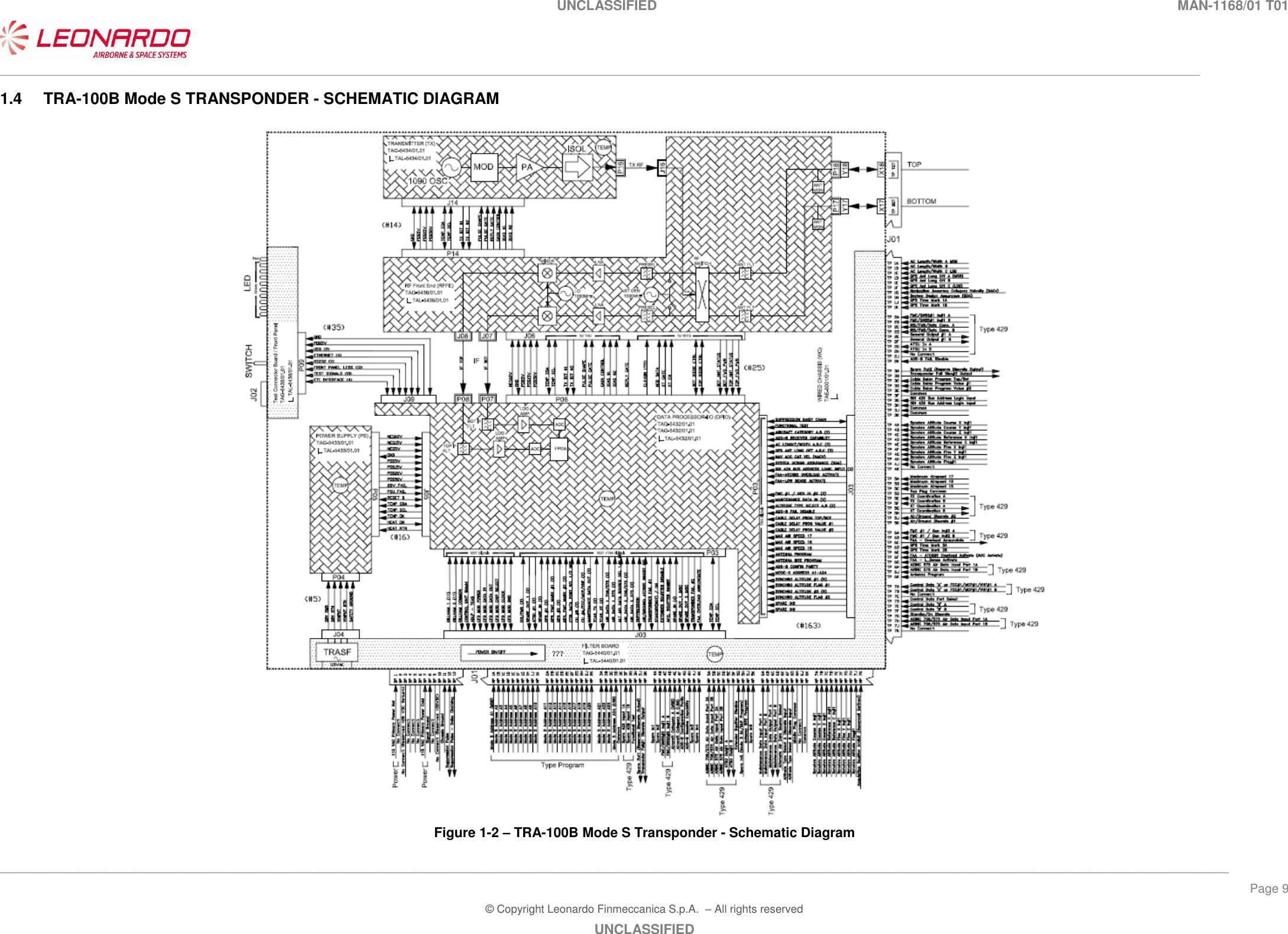
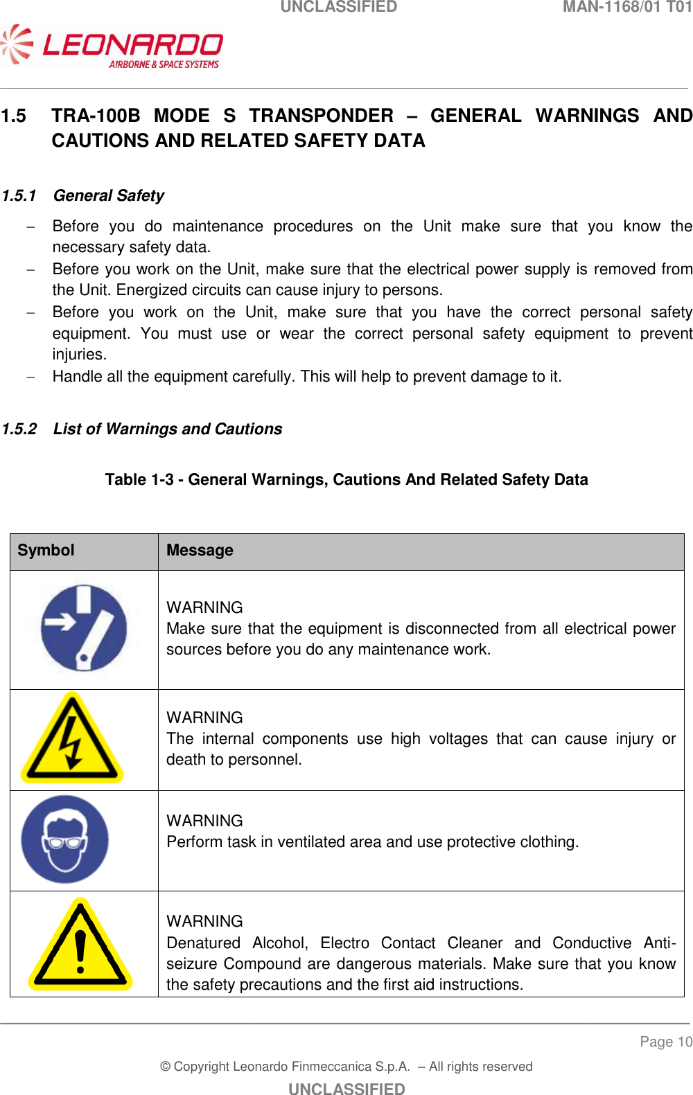
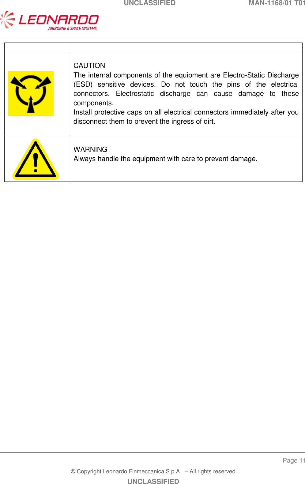
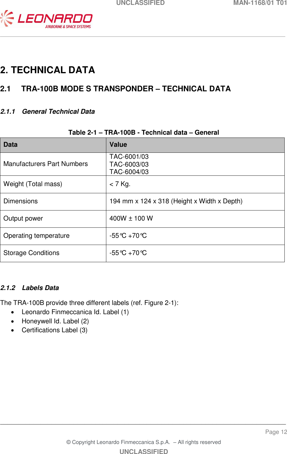
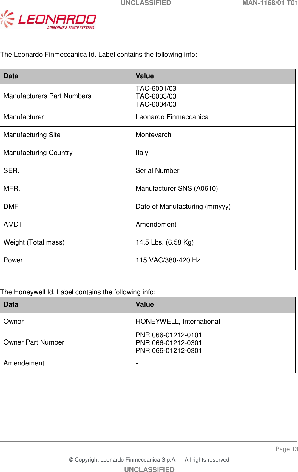
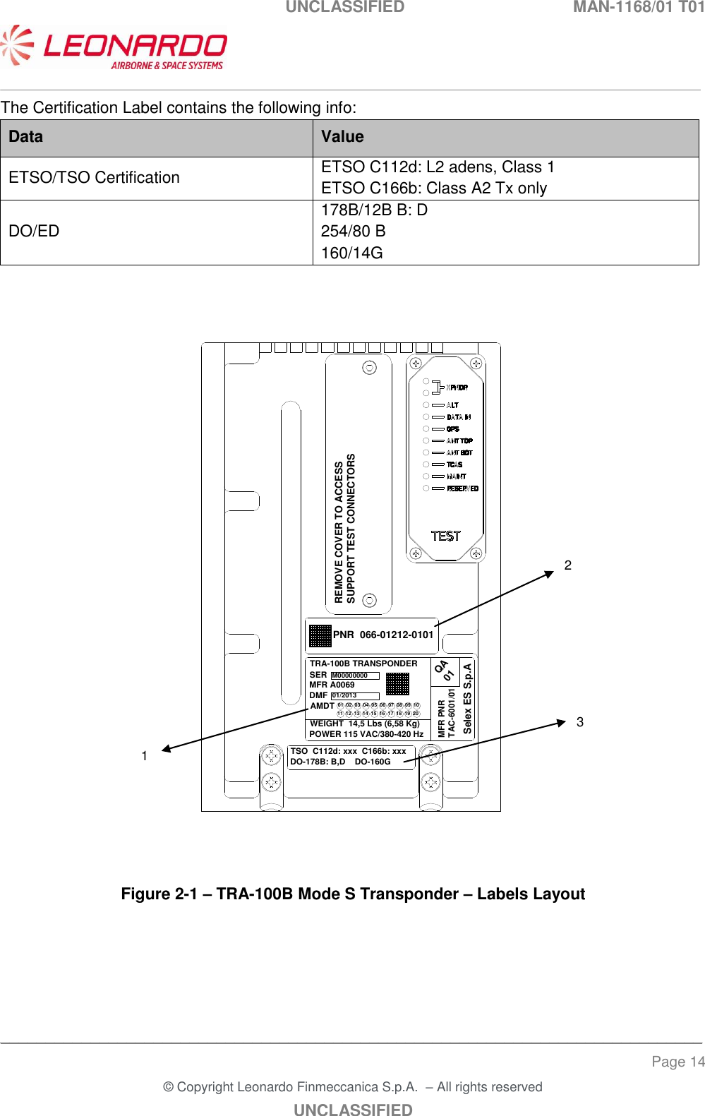
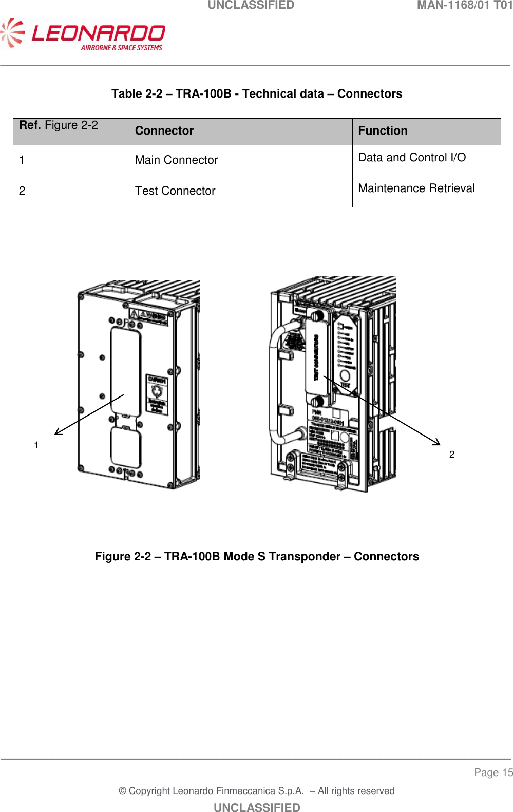
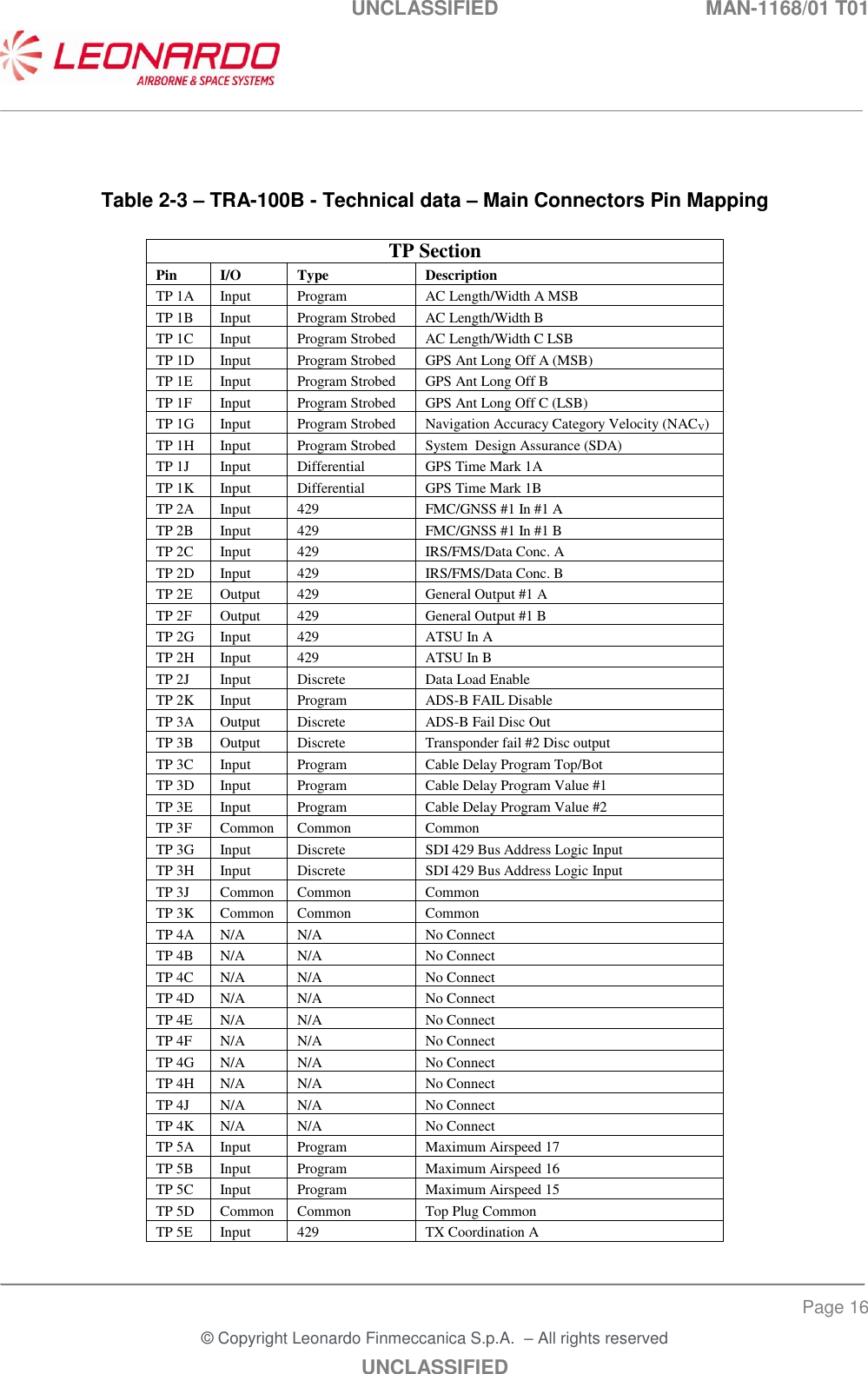
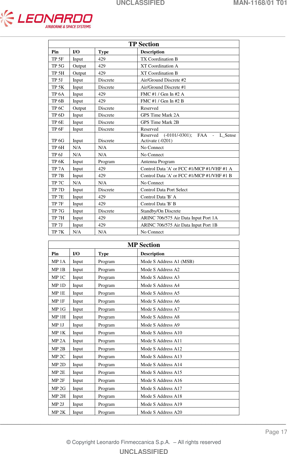
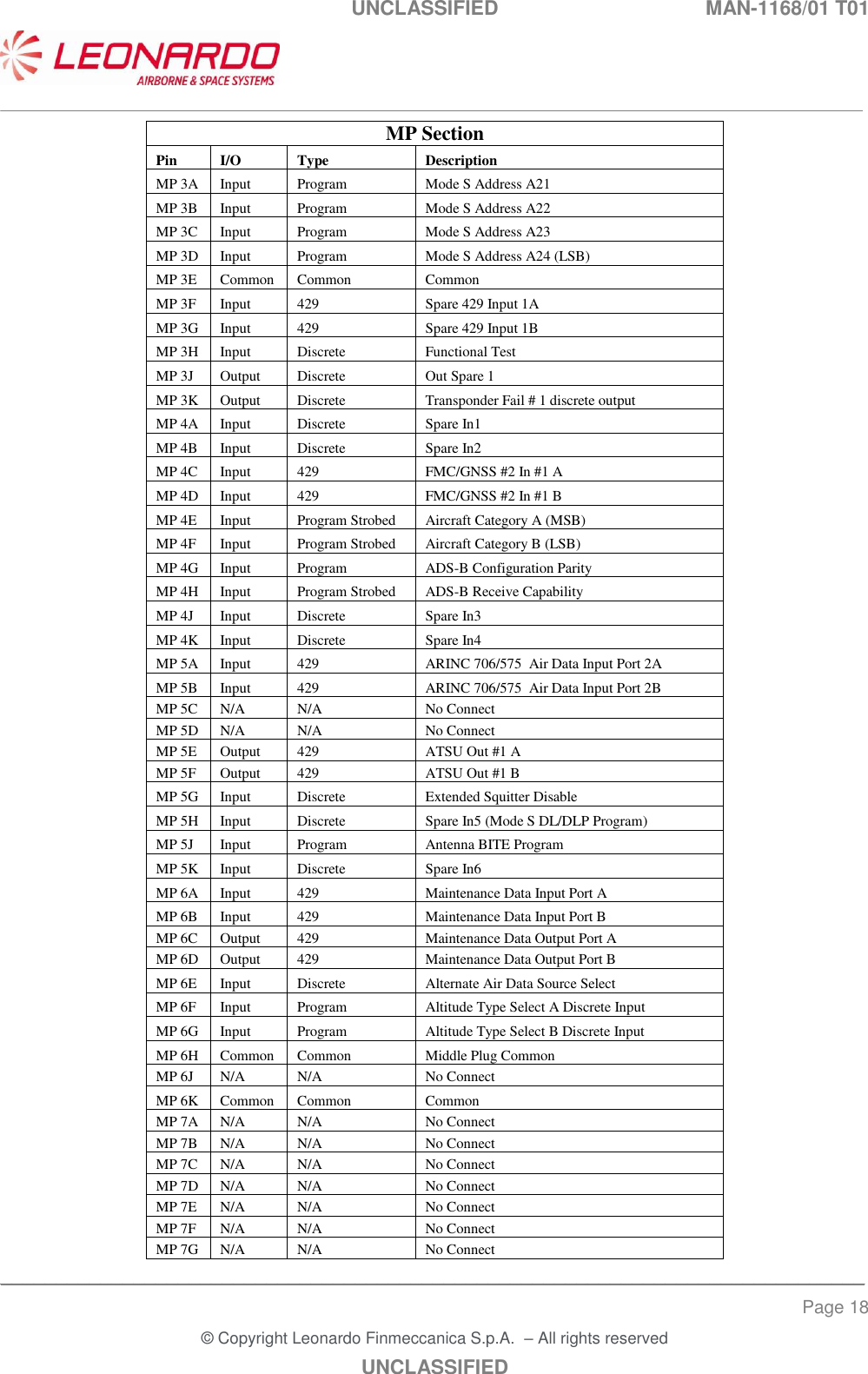
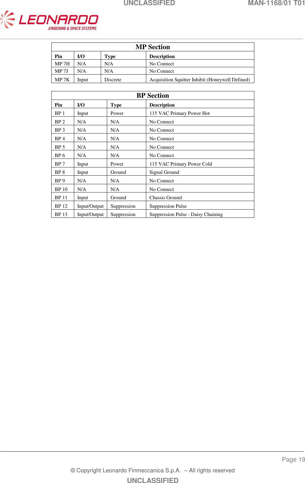
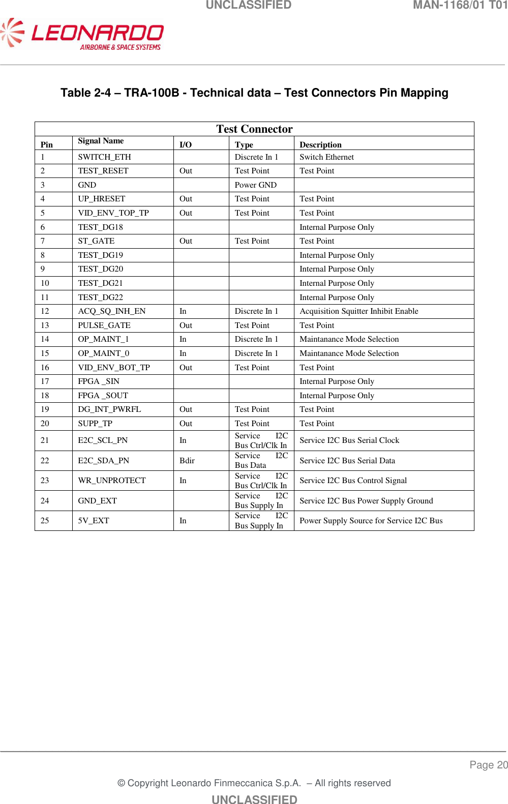
Users manual 2