Libelium Comunicaciones Distribuidas S L PARKING-V1 Wireless sensor node for Smart Parking (Internet of Things) User Manual 08 User manual v1
Libelium Comunicaciones Distribuidas S.L. Wireless sensor node for Smart Parking (Internet of Things) 08 User manual v1
User Manual


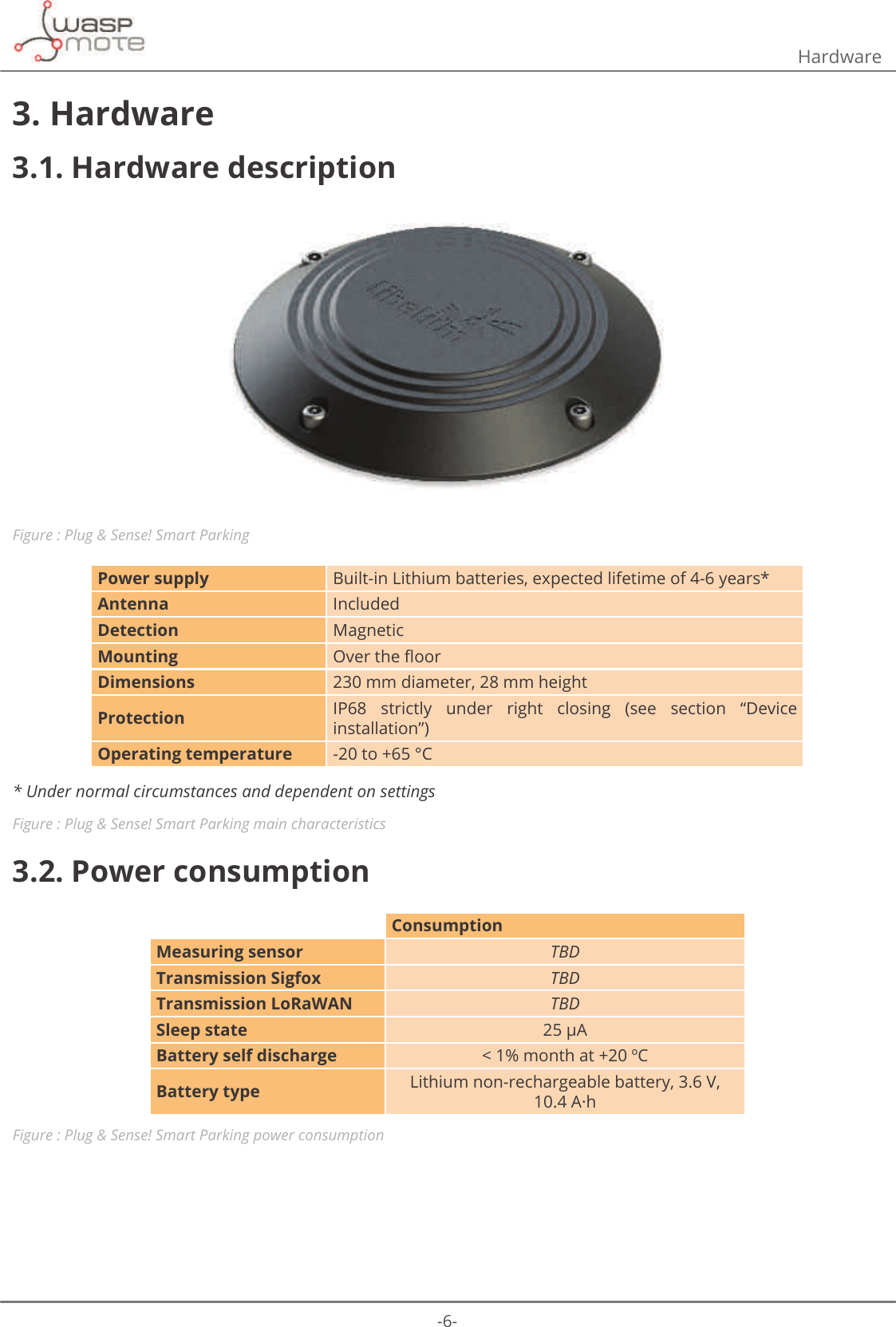
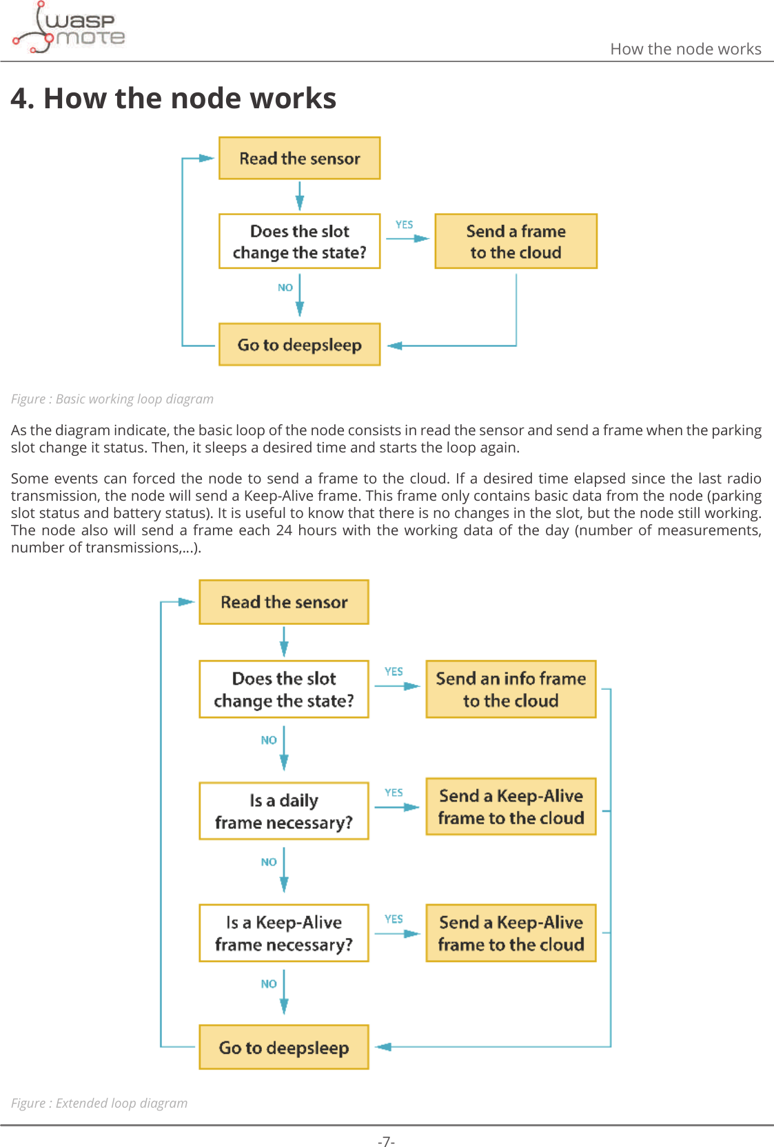
![-8-Sleep modes5. Sleep modesPlug & Sense! Smart Parking has 2 sleep modes: day mode and night mode. The second one has been developed WRXVHZKHQWKHSDUNLQJVORWLVH[SHFWHGWRKDYHIHZHUFKDQJHVLHDWQLJKW(DFKPRGHKDVLWVRZQFRQȴJXUDWLRQSDUDPHWHUV7KHȴJXUHEHORZVKRZVDQH[DPSOHIRUWKHQRGHWUDQVPLVVLRQVLQDGD\7KHWLPH]RQHEHWZHHQAM and 12 AM (in light gray) indicates that the node is working in day mode. In this mode, the sampling of the parking slot is made more regular (1 minute) and the Keep-Alive is only 2 hours. In the dark gray zone, from 12 AM to 6 AM, the node is working in night mode. As is shown in the example, the sampling time is greater (10 minutes) and the Keep-Alive increases too (3 hours). ([DPSOHFRQȴJXUDWLRQParameter &RQȴJXUDWLRQSleep time 1 minuteKeep-Alive 2 hoursNight Mode start hour 00 hoursNight Mode duration 6 hoursNight Mode Sleep Time 10 minutesNight Mode Keep-Alive 3 hoursFigure : ([DPSOHFRQȴJXUDWLRQFigure : Day and night modes example5.1. Day modeΖWLVWKHEDVLFZRUNLQJPRGHDQGLWKDVFRQȴJXUDEOHSDUDPHWHUV •Sleep time:6OHHSWLPHEHWZHHQFRQVHFXWLYHVHQVRUPHDVXUHPHQWVPLQXWHVRSWLRQLVFRQȴJXUHGE\GHIDXOW •Keep-Alive:(ODSVHGWLPHVLQFHODVWWUDQVPLVVLRQWRWULJJHUD.HHS$OLYHIUDPHKRXUVRSWLRQLVFRQȴJXUHGby default. This frame only contains basic data from the node (parking slot status and battery status). It is useful to know that there are no changes in the slot, but the node still working. This mode can be disabled using both the USB Programmer or the Remote Manager.](https://usermanual.wiki/Libelium-Comunicaciones-Distribuidas-S-L/PARKING-V1/User-Guide-3452582-Page-8.png)

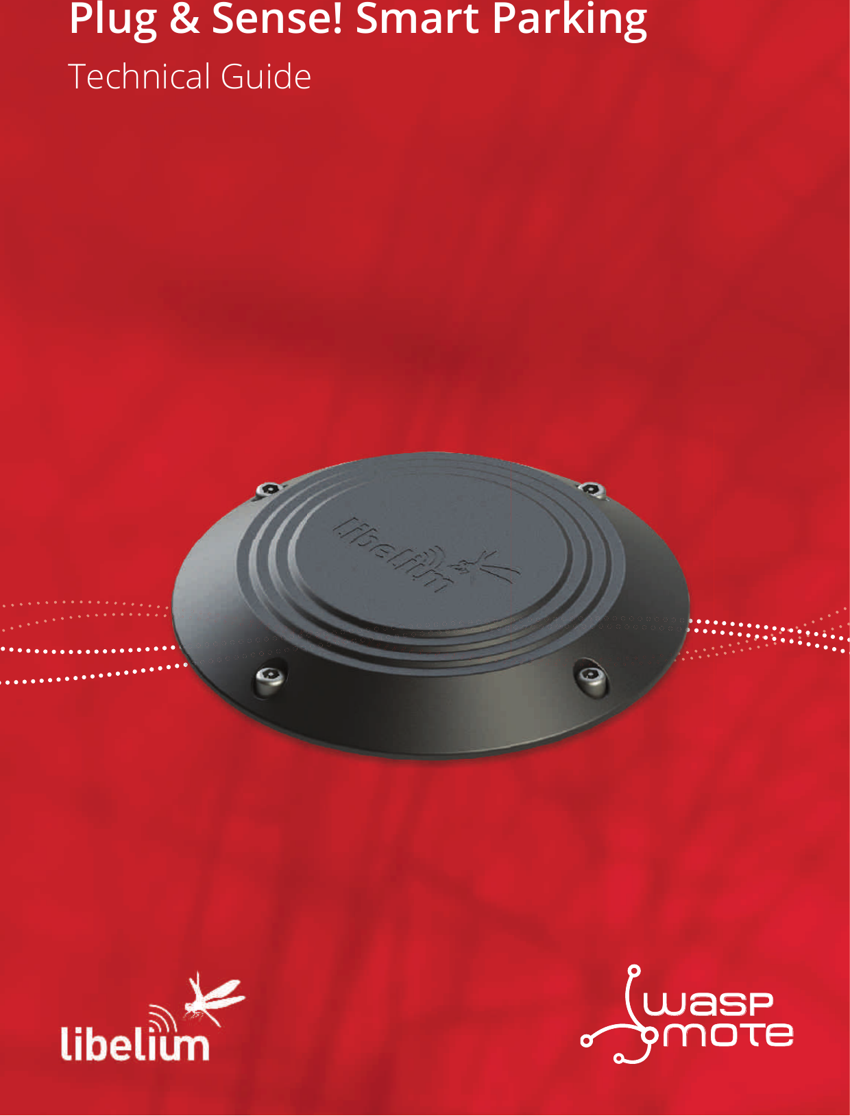
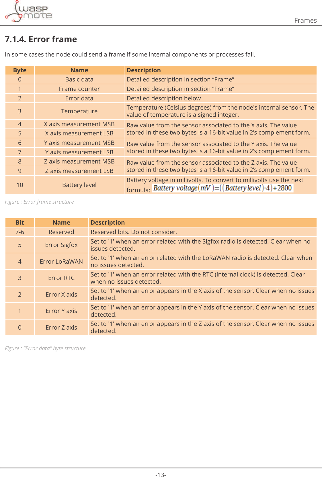
![-12-Frames7.1.2. Keep-Alive frameThis frame is used to indicate that the parking slot has not changed, but the node is still working.Byte Name Description0 Basic data Detailed description in section “Frame”1 Frame counter Detailed description in section “Frame”2 Timestamp (hh) Current hours3 Timestamp (mm) Current minutes4 Temperature Temperature (Celsius degrees) from the node's internal sensor. The value of temperature is a signed integer.5 X axis measurement MSB Raw value from the sensor associated to the X axis. The value stored in these two bytes is a 16-bit value in 2’s complement form,.6 X axis measurement LSB7 Y axis measurement MSB Raw value from the sensor associated to the Y axis. The value stored in these two bytes is a 16-bit value in 2’s complement form.8 Y axis measurement LSB9 Z axis measurement MSB Raw value from the sensor associated to the Z axis. The value stored in these two bytes is a 16-bit value in 2’s complement form.10 Z axis measurement LSBFigure : Keep-Alive frame structure7.1.3. Daily update frameThis frame is sent daily at 1 AM. It contains a little summary.Byte Name Description0 Basic data Detailed description in section “Frame”1 Frame counter Detailed description in section “Frame”2 Sensor measurements MSB Unsigned 16 bit counter. It stores the times that the sensor is used in the last 24 hours. 3 Sensor measurements LSB4 Sigfox transmissions MSB Unsigned 16 bit counter. It stores the times that Sigfox radio is used in the last 24 hours. 5 Sigfox transmissions LSB6 LoRaWAN transmissions MSB Unsigned 16 bit counter. It stores the times that LoRaWAN radio is used in the last 24 hours. 7 LoRaWAN transmissions LSB8 Resets Number of resets generated in the last 24 hours9&RQȴJBLG 9DOXHRIWKHFRQȴJXUDWLRQYHUVLRQORDGHGLQWRWKHQRGH10 Reserved Reserved bytes. Do not consider. Figure : Daily update frame structureThis frame can be deactivated using the Plug & Sense! Smart Parking USB Programmer or via radio, with the Remote Manager, setting to 0 the enable/disable daily frame bit. The daily update frame is very special because the node waits for a response after it is sent. This response is useful IRUUHFRQȴJXULQJWKHQRGHȊRYHUWKHDLUȋZLWKRXWSK\VLFDODFFHVV$OVRDVHFRQGXVHRIWKLVUHVSRQVHIUDPHLVWRV\QFKURQL]HWKHQRGHȇVLQWHUQDOFORFNWKDQNVWRDWLPHVWDPS7KLVUHVSRQVHFDQEHFRQȴJXUHGXVLQJWKHUHPRWHPHP.](https://usermanual.wiki/Libelium-Comunicaciones-Distribuidas-S-L/PARKING-V1/User-Guide-3452582-Page-12.png)
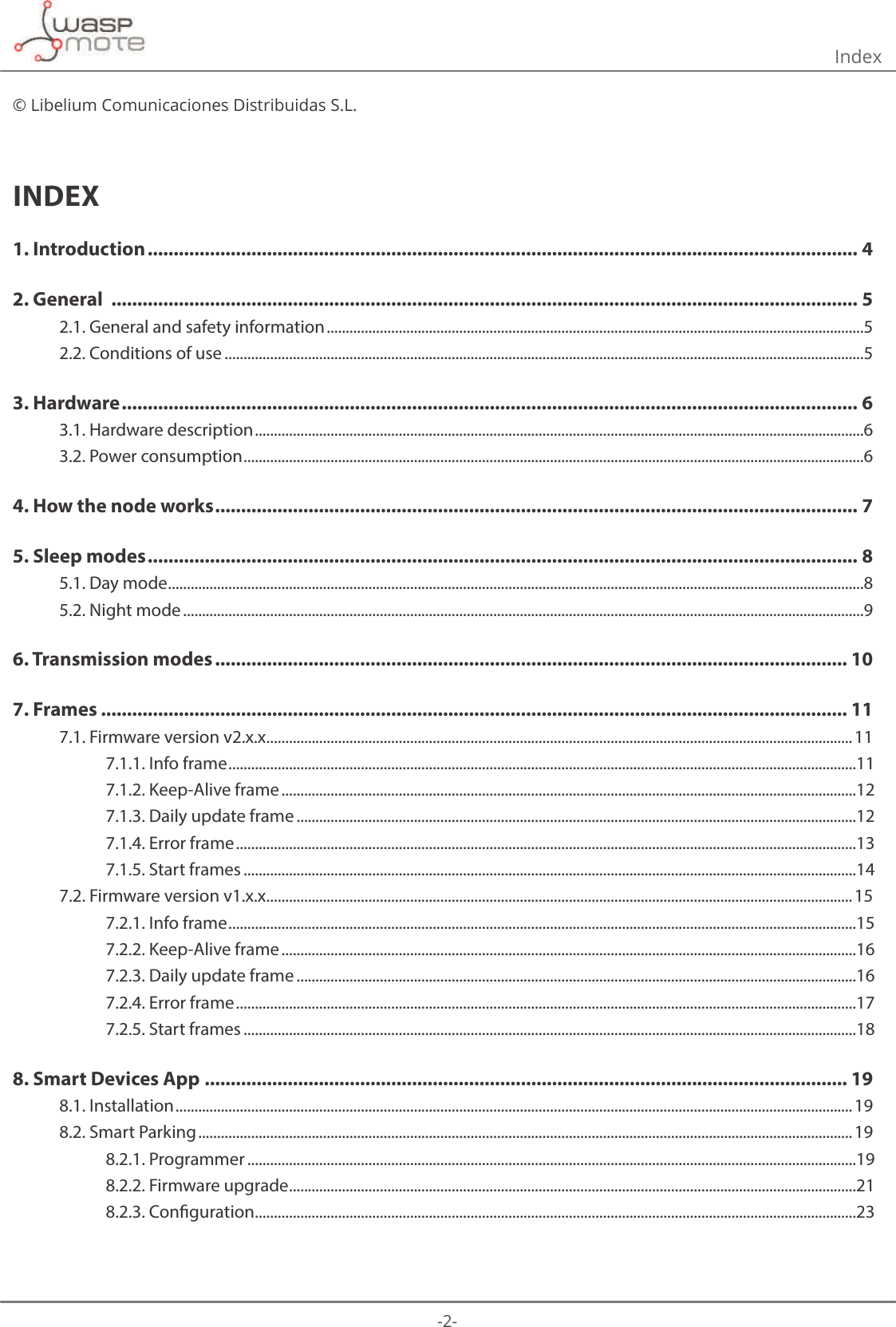
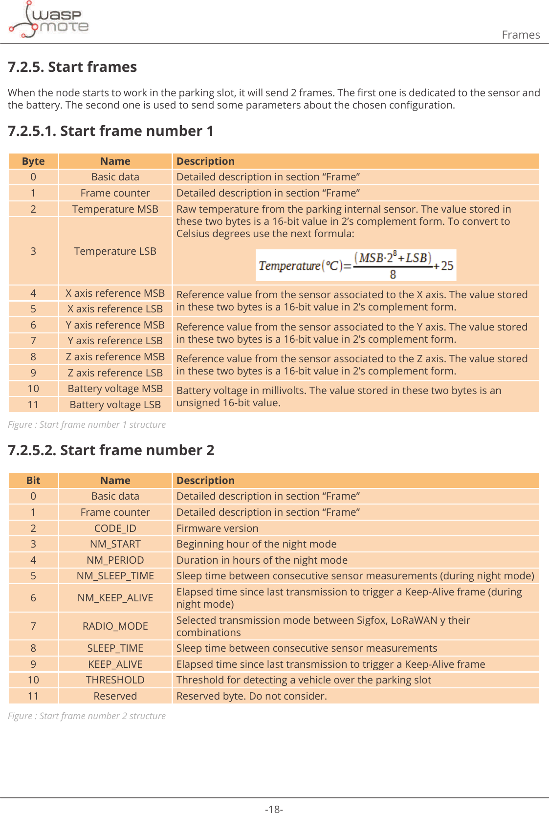
![-16-Frames7.2.2. Keep-Alive frameThis frame is used to indicate that the parking slot has not changed, but the node is still working.Byte Name Description0 Basic data Detailed description in section “Frame”1 Frame counter Detailed description in section “Frame”2 Timestamp (hh) Current hours3 Timestamp (mm) Current minutes4 Temperature MSB Raw temperature from the node’s internal sensor. The value stored in these two bytes is a 16-bit value in 2’s complement form. To convert to Celsius degrees use the next formula:5 Temperature LSB6 X axis measurement MSB Raw value from the sensor associated to the X axis. The value stored in these two bytes is a 16-bit value in 2’s complement form.7 X axis measurement LSB8 Y axis measurement MSB Raw value from the sensor associated to the Y axis. The value stored in these two bytes is a 16-bit value in 2’s complement form.9 Y axis measurement LSB10 Z axis measurement MSB Raw value from the sensor associated to the Z axis. The value stored in these two bytes is a 16-bit value in 2’s complement form.11 Z axis measurement LSBFigure : Keep-Alive frame structure7.2.3. Daily update frameThis frame is sent daily at 1 AM. It contains a little summary.Byte Name Description0 Basic data Detailed description in section “Frame”1 Frame counter Detailed description in section “Frame”2 Sensor measurements MSB Unsigned 16 bit counter. It stores the times that the sensor is used in the last 24 hours. 3 Sensor measurements LSB4 Sigfox transmissions MSB Unsigned 16 bit counter. It stores the times that Sigfox radio is used in the last 24 hours. 5 Sigfox transmissions LSB6 LoRaWAN transmissions MSB Unsigned 16 bit counter. It stores the times that LoRaWAN radio is used in the last 24 hours. 7 LoRaWAN transmissions LSB8 Resets Number of resets generated in the last 24 hours9&RQȴJBLG 9DOXHRIWKHFRQȴJXUDWLRQYHUVLRQORDGHGLQWRWKHQRGH10-11 Reserved Reserved bytes. Do not consider. Figure : Daily update frame structureThis frame can be deactivated using the Plug & Sense! Smart Parking USB Programmer or via radio, with the Remote Manager, setting to 0 the enable/disable daily frame bit. The daily update frame is very special because the node waits for a response after it is sent. This response is useful IRUUHFRQȴJXULQJWKHQRGHȊRYHUWKHDLUȋZLWKRXWSK\VLFDODFFHVV$OVRDVHFRQGXVHRIWKLVUHVSRQVHIUDPHLVWRV\QFKURQL]HWKHQRGHȇVLQWHUQDOFORFNWKDQNVWRDWLPHVWDPS7KLVUHVSRQVHFDQEHFRQȴJXUHGXVLQJWKHUHPRWHPHP.](https://usermanual.wiki/Libelium-Comunicaciones-Distribuidas-S-L/PARKING-V1/User-Guide-3452582-Page-16.png)
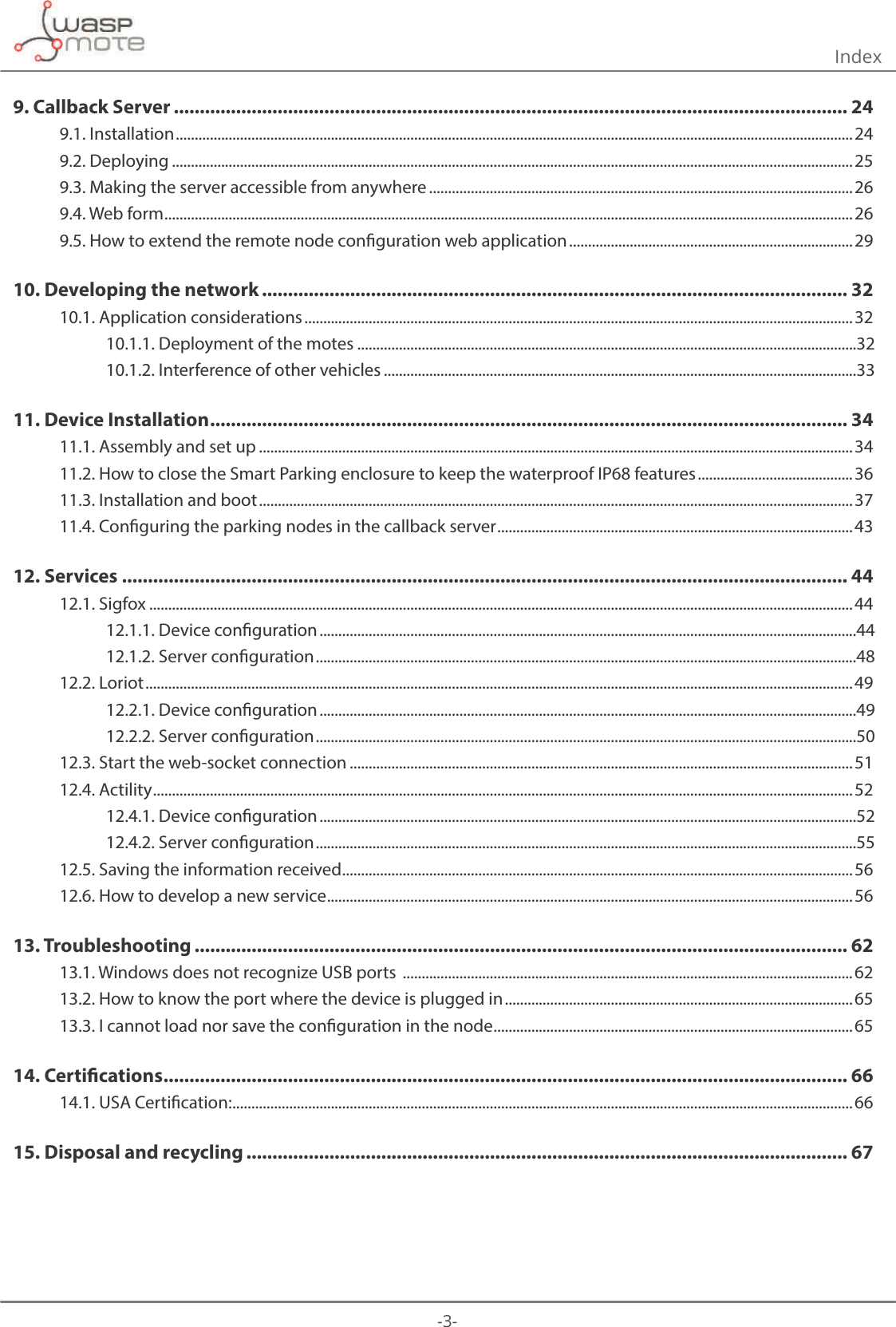
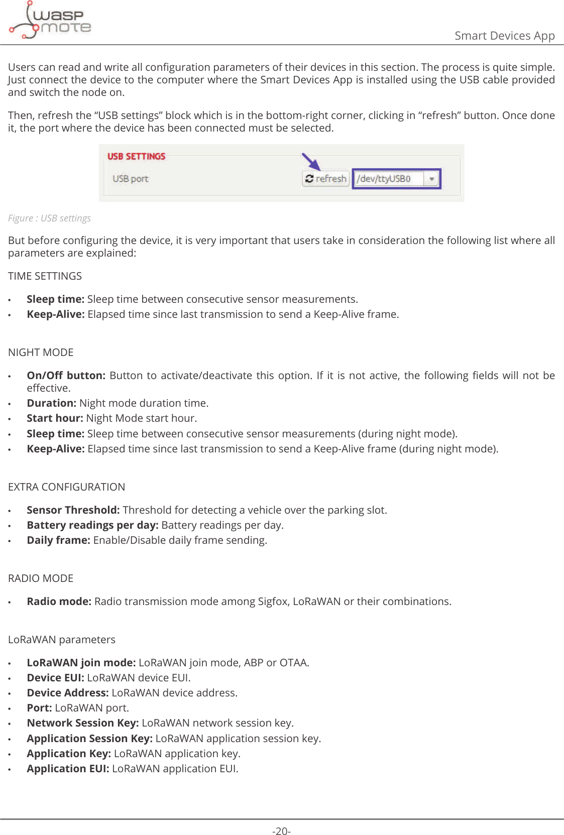
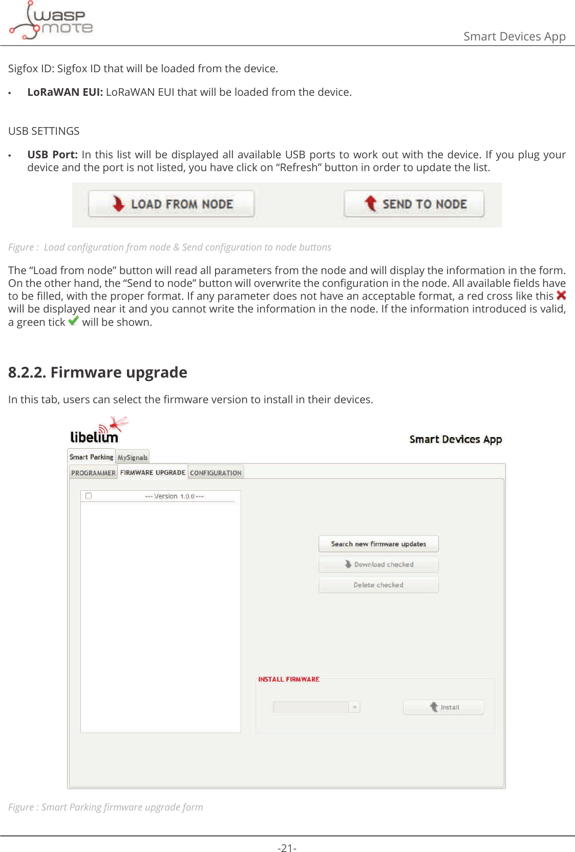
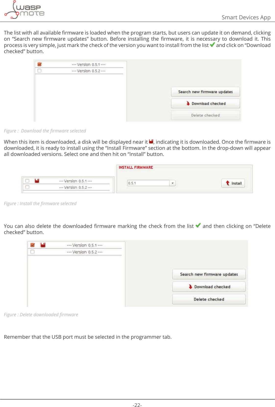
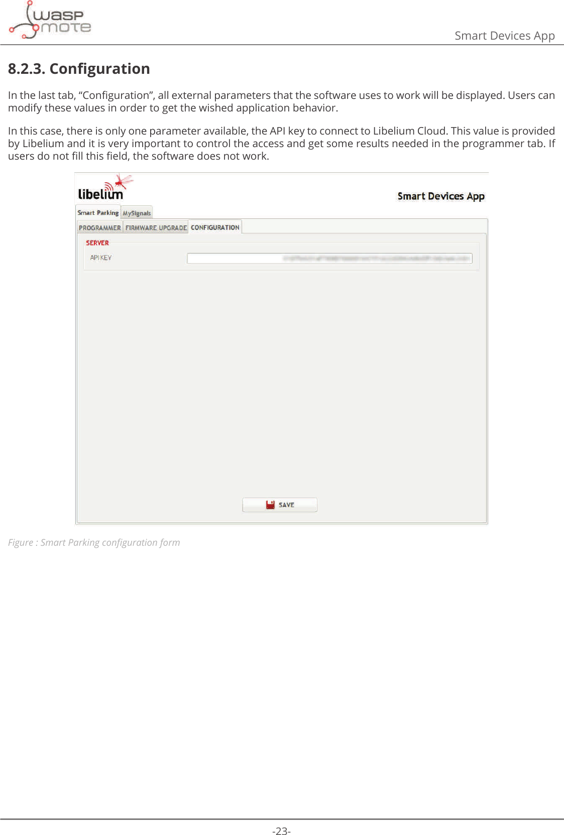
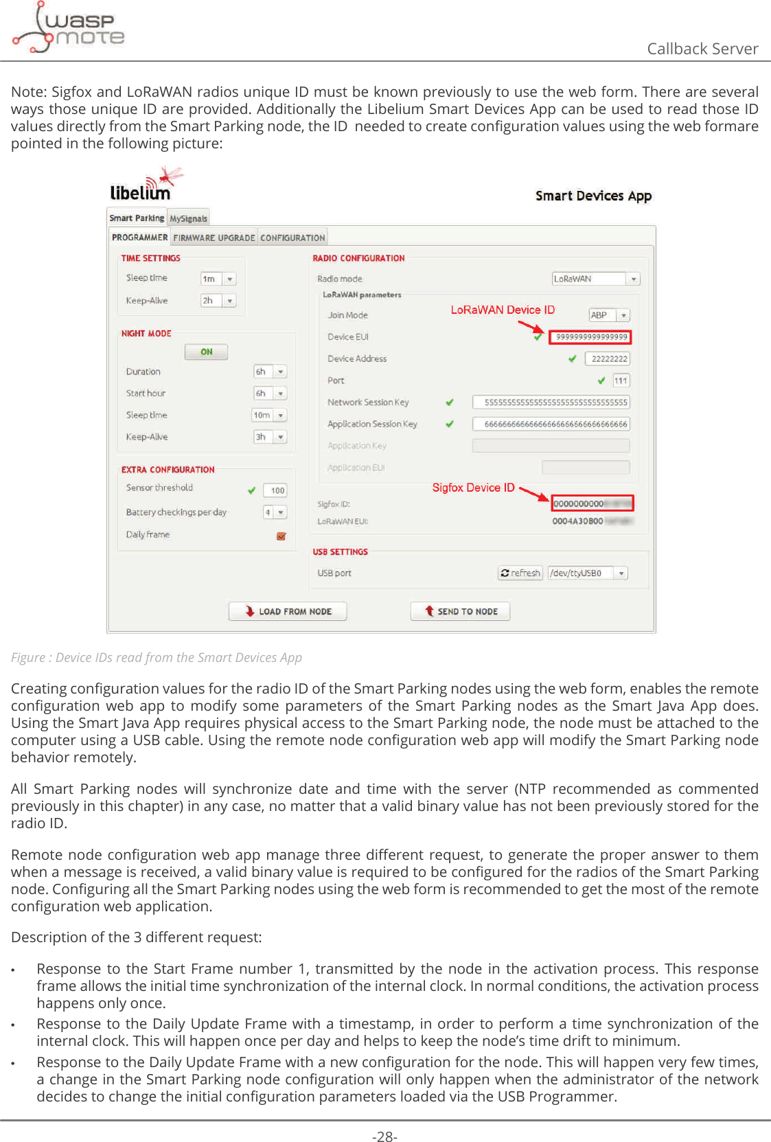
![-19-Smart Devices App8. Smart Devices App/LEHOLXP6PDUW'HYLFHV$SSLVDQLPSRUWDQWWRROGHYHORSHGE\/LEHOLXPWKDWDOORZVXVHUVLQVWDOOQHZȴUPZDUHYHUVLRQVDQG SURJUDP WKH FRQȴJXUDWLRQ RI WKH QHZ /LEHOLXP GHYLFHV LQ D IHZ FOLFNV $W WKHPRPHQW LW LV RQO\available for Smart Parking and MySignals products, but the list will be incremented shortly.8.1. InstallationFirst of all and before installing anything, users have to take into account the platform where the application is going to be installed. To install the Libelium Smart Devices App, it is compulsory to have installed the JDK 1.8. If it is not installed in the computer, you can follow the steps and download it from this website: https://docs.oracle.com/javase/8/docs/technotes/guides/install/install_overview.htmlOnce installed JDK, users can download the application using the appropriate link depending on the operative system: •Ubuntu: http://downloads.libelium.com/smart_device_app/SmartDeviceApp_linux64.zip •Windows: http://downloads.libelium.com/smart_device_app/SmartDeviceApp_windows32.zip •Mac: http://downloads.libelium.com/smart_device_app/SmartDeviceApp_macosx64.zip7KHQFXVWRPHUVRQO\KDYHWRH[WUDFWWKHFRQWHQWRIWKH6PDUW'HYLFH$SS]LSȴOHGRZQORDGHGLQDSODFHZLWKWKHULJKWSHUPLVVLRQVDQGȴQDOO\H[HFXWHWKHȴOHFDOOHGȊ6PDUW'HYLFH$SSȋWKDWZLOOLQLWLDOL]HWKHDSSOLFDWLRQ3OHDVHQRWHWKDWWKHH[WHQVLRQRIWKLVȴOHZLOOGHSHQGRQWKHRSHUDWLQJV\VWHPWKHXVHULVXVLQJDWWKHPRPHQWVKIRULinux and OSX, and .bat for Windows).8.2. Smart ParkingThis section provides several options to Smart Parking users in order to take full advantage of all possibilities the GHYLFHVRHUV8.2.1. ProgrammerFigure : 6PDUW3DUNLQJFRQȴJXUDWLRQIRUP](https://usermanual.wiki/Libelium-Comunicaciones-Distribuidas-S-L/PARKING-V1/User-Guide-3452582-Page-19.png)
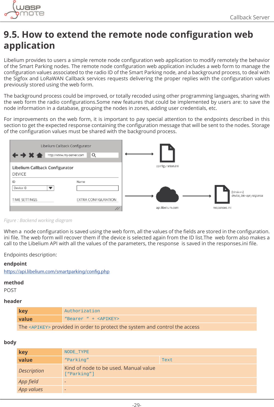
![-25-Callback Server9.2. Deploying6WHS([WUDFWLQ\RXUVHUYHUWKH=Ζ3ȴOHSURYLGHGE\/LEHOLXPFRQWDLQLQJWKHUHPRWHQRGHFRQȴJXUDWLRQZHEDSSOLFDWLRQVRXUFHȴOHV6WHS&KHFNWKHULJKWRZQHUJURXSDQGSHUPLVVLRQVRIDOOWKHȴOHVH[WUDFWHGXVXDOO\XVLQJZZZGDWDJURXSLVdefault in Ubuntu environment. 6WHS&KHFNWKHSHUPLVVLRQVRIDOOIROGHUVDQGȴOHVXVXDOO\XVLQJIRUGLUHFWRULHVDQGIRUȴOHVLVGHIDXOWin Ubuntu environment. 6WHS&RQȴJXUHWKHUHPRWHQRGHFRQȴJXUDWLRQZHEDSSOLFDWLRQFRQWH[WLQ\RXUVHUYHUZLWKWKHSDWKZKHUHWKHVRXUFHȴOHVZHUHH[WUDFWHG([DPSOHFRQȴJXUDWLRQIRUDVHUYHUUXQQLQJ8EXQWXRSHUDWLQJV\VWHPDQG$SDFKHZHEVHUYHU&UHDWHDQHZFRQȴJXUDWLRQȴOHP\BVHUYHUFRQILQHWFDSDFKHVLWHVDYDLODEOHGLUHFWRU\P\BVHUYHUFRQIH[DPSOHȴOHUHSODFHSDWKVWRPDWFK\RXUVHUYHUGHSOR\PHQWORFDWLRQV<VirtualHost *:80> ServerAdmin webmaster@localhost ServerName my_server.com ServerAlias my_server.com DirectoryIndex index.html index.php DocumentRoot /path/zip/extracted ErrorLog ${APACHE_LOG_DIR}/error.log CustomLog ${APACHE_LOG_DIR}/access.log combined <Directory /path/zip/extracted> Options Indexes FollowSymLinks AllowOverride All Require all granted </Directory></VirtualHost>6WHSΖVPDQGDWRU\WRZULWHWKHFXVWRPHUȇV$3Ζ.(<LQWKHVHUYHUFRQȴJXUDWLRQȴOHDYDOLG$3Ζ.(<ZLOOEHSURYLGHGby your Libelium sales representative. ΖIWKHȊDSLNH\ȋSDUDPHWHULVQRWSURSHUO\FRQȴJXUHGWKHUHPRWHQRGHFRQȴJXUDWLRQZHEDSSOLFDWLRQZLOOQRWZRUN7KHVHUYHUFRQȴJXUDWLRQȴOHLVORFDWHGLQdata/app.iniLQVLGHWKHIROGHUZKHUHWKHFXVWRPHUH[WUDFWHGWKH]LSȴOHLQ6WHS7KHSDWWHUQRIWKLVȴOHLV[app]VHUYHU ߙKWWSVDSLOLEHOLXPFRPVPDUWSDUNLQJFRQࢱJSKSߚDSLNH\ ߙߚserver:85/WRUHPRWHQRGHFRQȴJXUDWLRQVHUYLFHKRVWHGLQ/LEHOLXPȇVVHUYHUVapikey: unique API KEY provided by Libelium to identify the customer, must be double quoted. 6WHS(QDEOHWKLVQHZFRQȴJXUDWLRQVLWHFUHDWHGDQGUHVWDUWWKH$SDFKHVHUYHUXVXDOO\WKHFRPPDQGȊDHQVLWHP\BVHUYHUȋZLOOGRWKHWDVNLQ8EXQWXHQYLURQPHQW$ JRRG GDWH DQG WLPH VHUYHU FRQȴJXUDWLRQ LV UHFRPPHQGHG LQ RUGHU WR JXDUDQWHH WKH GDWD LQWHJULW\ RIthe information sent to the Smart Parking nodes,using an NTP server to keep the clock system up to date is recommended.](https://usermanual.wiki/Libelium-Comunicaciones-Distribuidas-S-L/PARKING-V1/User-Guide-3452582-Page-25.png)
![-30-Callback Serverkey BAT_READINGvalue [0-7] TextDescription Number of daily battery level checking$SSȴHOG ([WUDFRQȴJXUDWLRQ%DWWHU\FKHFNLQJSHUGD\App values [0 = 1 | 1 = 2 | 2 = 3 | 3 = 4 | 4 = 5 | 5 = 6 | 6 = 7 | 7 = 8]key RADIO_MODEvalue [0-4] TextDescription Selected transmission mode$SSȴHOG 5DGLRFRQȴJXUDWLRQ5DGLRPRGHApp values > 6LJIR[_ /R5D:$1_ 6LJIR[/R5D:$1_ 6LJIR[ࠥ/R5D:$1_ /R5D:$1ࠥ6LJIR[@key THRESHOLDvalue [0-255] TextDescription Threshold for detecting a vehicle over the parking slot$SSȴHOG ([WUDFRQȴJXUDWLRQ6HQVRUWKUHVKROGApp values [0 = 1| 1 = 2 | 2 = 3 | 3 = 4 | 4 = 5 | … | 255 - 256]key SLEEP_TIMEvalue [0-31] TextDescription Sleep time between consecutive sensor measurements$SSȴHOG Time Settings - Sleep timeApp values[0 = 1m | 1 = 2m | 2 = 3m | 3 = 4m | 4 = 5m | 5 = 10m | 6 = 15m | 7 = 20m | 8 = 30m | 9 = 1h | 10 = 2h | 11 = 3h | 12 = 4h | 13 = 5h | 14 = 6h | 15 = 7h | 16 = 8h | 17 = 9h | 18 = 10h | 19 = 11h | 20 = 12h | 21 = 13h | 22 = 14h | 23 = 15h | 24 = 16h | 25 = 17h | 26 = 18h | 27 = 19h | 28 = 20h | 29 = 21h | 30 = 22h | 31 = 24h]m = minutesh = hourskey KEEP_ALIVEvalue [0-15] TextDescription Elapsed time since last transmission to send a Keep-Alive frame$SSȴHOG Time Settings - Keep-AliveApp values[0 = 0h | 1 = 0.5h | 2 = 1h | 3 = 2h | 4 = 3h | 5 = 4h | 6 = 5h | 7 = 6h | 8 = 8h | 9 = 10h | 10 = 12h | 11 = 14h | 12 = 16h | 13 = 18h | 14 = 20h | 15 = 24h]h = hourskey NM_STARTvalue [0-23] TextDescription Beginning hour of the night mode$SSȴHOG Night mode – Start hourApp values[0 = 0h | 1 = 1h | 2 = 2h | 3 = 3h | 4 = 4h | 5 = 5h | 6 = 6h | 7 = 7h | 8 = 8h | 9 = 9h | 10 = 10h | 11 = 11h | 12 = 12h | 13 = 13h | 14 = 14h | 15 = 15h | 16 = 16h | 17 = 17h | 18 = 18h | 19 = 19h | 20 = 20h | 21 = 21h | 22 = 22h | 23 = 23h]h = hours](https://usermanual.wiki/Libelium-Comunicaciones-Distribuidas-S-L/PARKING-V1/User-Guide-3452582-Page-30.png)
![-31-Callback Serverkey NM_PERIODvalue [0-15] TextDescription Night mode duration time$SSȴHOG Night mode - DurationApp values[0 = 0h | 1 = 1h | 2 = 2h | 3 = 3h | 4 = 4h | 5 = 5h | 6 = 6h | 7 = 7h | 8 = 8h | 9 = 9h | 10 = 10h | 11 = 11h | 12 = 12h | 13 = 13h | 14 = 14h | 15 = 15h]h = hourskey NM_SLEEP_TIMEvalue [0-15] TextDescription Sleep time between consecutive sensor measurements (during night mode)$SSȴHOG Night mode – Sleep timeApp values[0 = 2m | 1 = 5m | 2 = 10m | 3 = 15m | 4 = 20m | 5 = 30m | 6 = 1h | 7 = 2h | 8 = 3h | 9 = 4h | 10 = 5h | 11 = 6h | 12 = 8h | 13 = 10h | 14 = 12h | 15 = 14h]m = minutesh = hourskey NM_KEEP_ALIVEvalue [0-15] TextDescription Elapsed time since last transmission to send a Keep-Alive frame (during night mode)$SSȴHOG Night mode – Sleep timeApp values[0 = 0h | 1 = 1h | 2 = 2h | 3 = 3h | 4 = 4h | 5 = 5h | 6 = 6h | 7 = 7h | 8 = 8h | 9 = 9h | 10 = 10h | 11 = 11h | 12 = 12h | 13 = 13h | 14 = 14h | 15 = 15h]h = hourskey CONFIG_IDvalue [1-255] TextDescription 9HUVLRQQXPEHURIWKHFRQȴJXUDWLRQ$SSȴHOG ([WUDFRQȴJXUDWLRQȂ&RQȴJXUDWLRQYHUVLRQApp values [1-255]responseUsers will receive a JSON string with these possibilities:{ߙHUURUߚ7H[W}Error received from the API system validation. text contains the error detail.{ߙVWDWXVߚ>2._12.@ߙGDWDߚ7H[W}Information received after all values have been evaluated. NOK status includes in data the error detail. OK status includes in data the string to be saved in GDWDFRQࢱJXUDWLRQ.LQLȴOHDVVRFLDWHGWRWKHdevice ID provided.](https://usermanual.wiki/Libelium-Comunicaciones-Distribuidas-S-L/PARKING-V1/User-Guide-3452582-Page-31.png)

![-48-Services12.1.2. 6HUYHUFRQȴJXUDWLRQΖQWKHFDOOEDFNVHUYHUSUHYLRXVO\LQVWDOOHGVRPHSDUDPHWHUVPXVWEHFRQȴJXUHGWRHQDEHWKHFRPPXQLFDWLRQwith the node.7KHVHUYLFHVLQLȴOHORFDWHGLQGDWDIROGHUKDVWREHXSGDWHGZLWKWKHIROORZLQJLQIRUPDWLRQLQWKHVLJIR[VHFWLRQ[sigfox]ORJBOHYHO ߙ$//ߚORJBࢱOH ߙORJVVLJIR[ORJߚ •log_level: This level is the minimum level to save logs in the system. Select among these levels: -OFF: This option deactivate the log. -ERROR : It only reports ERROR messages. -INFO: It reports ERROR + INFO messages. -DEBUG: it reports ERROR + INFO + DEBUG messages. -ALL: It reports everything happened in the process. •ORJBȴOH The relative path where the log messages will be saved.](https://usermanual.wiki/Libelium-Comunicaciones-Distribuidas-S-L/PARKING-V1/User-Guide-3452582-Page-48.png)
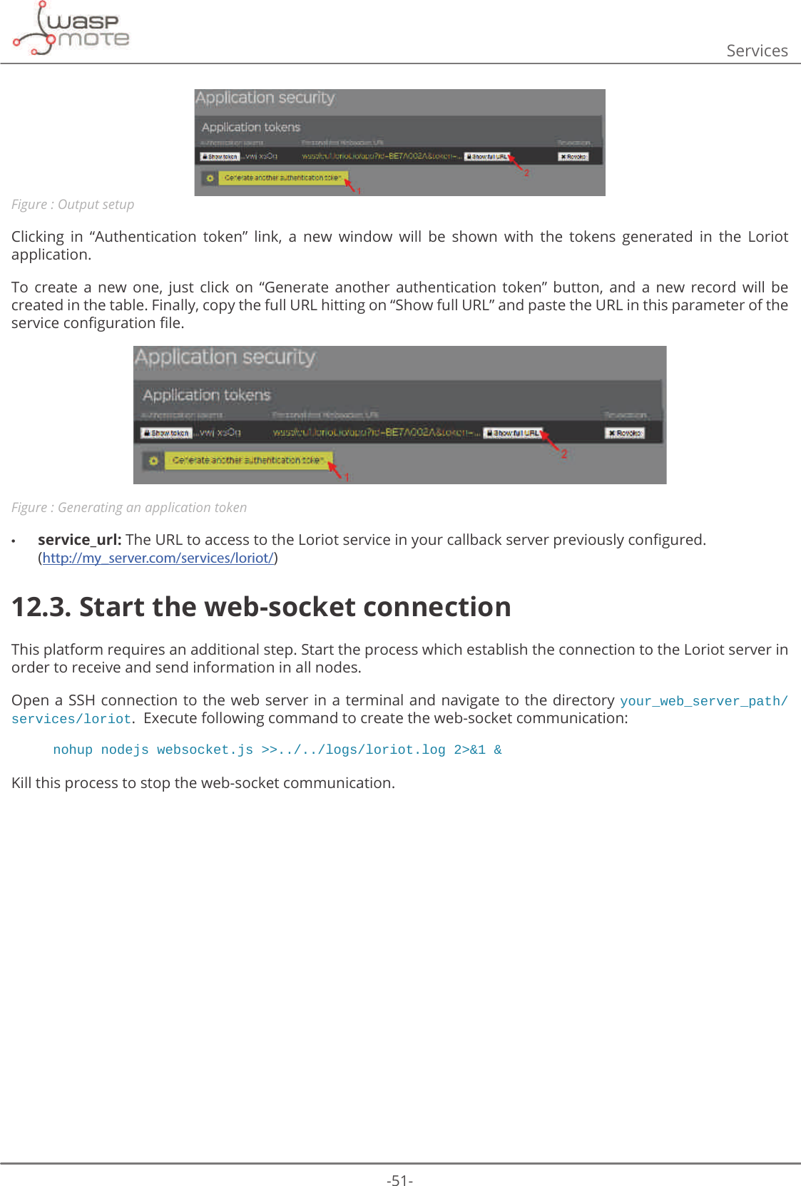
![-50-ServicesClick on “Edit output” to display all the information available about the selected output option.Click on “Change” button in the detailed window to change the data output, select one of the multiple choices from the list. Figure : Selecting the output application“Websocket” is the method recommended to deliver the end-device data. •ΖWȇVFORXGIULHQGO\H[LVWLQJ+773WUDɝFRSWLPL]DWLRQFDQEHXVHG •It’s bi-directional, real-time interface •It’s easy to implement •It’s lower overhead compared to REST •It’s already supported in all major web browsers •It’s already supported in many programming languages12.2.2. 6HUYHUFRQȴJXUDWLRQΖQWKHFDOOEDFNVHUYHUSUHYLRXVO\LQVWDOOHGVRPHSDUDPHWHUVPXVWEHFRQȴJXUHGWRHQDEOHWKHFRPPXQLFDWLRQwith the node.The services.iniȴOH ORFDWHGLQ data folder, has to be updated with the following information in the loriot section.[loriot]ORJBOHYHO ߙ$//ߚORJBࢱOH ߙORJVORULRWORJߚZHEVRFNHWBXUO ߙZVVHXORULRWLRDSS"LG [[[[[[[WRNHQ [[[[[[[ߚVHUYLFHBXUO ߙKWWSP\VHUYHUFRPVHUYLFHVORULRWߚ •log_level: This level is the minimum level to save logs in the system. Select among these levels: -OFF: This option deactivate the log. -ERROR : It only reports ERROR messages. -INFO: It reports ERROR + INFO messages. -DEBUG: it reports ERROR + INFO + DEBUG messages. -ALL: It reports everything happened in the process. •ORJBȴOH The relative path where the log messages will be saved. •websocket_url: The URL of the websocket listed in the Loriot dashboard. In the last window shown “Application output”, in the second section “Current output setup” there are the target URL and the Authentication Token to access to the API interface.](https://usermanual.wiki/Libelium-Comunicaciones-Distribuidas-S-L/PARKING-V1/User-Guide-3452582-Page-50.png)
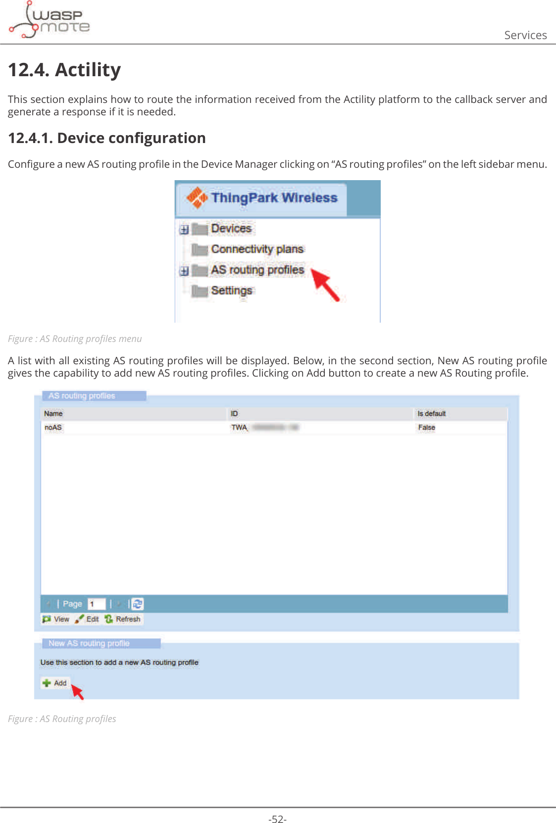
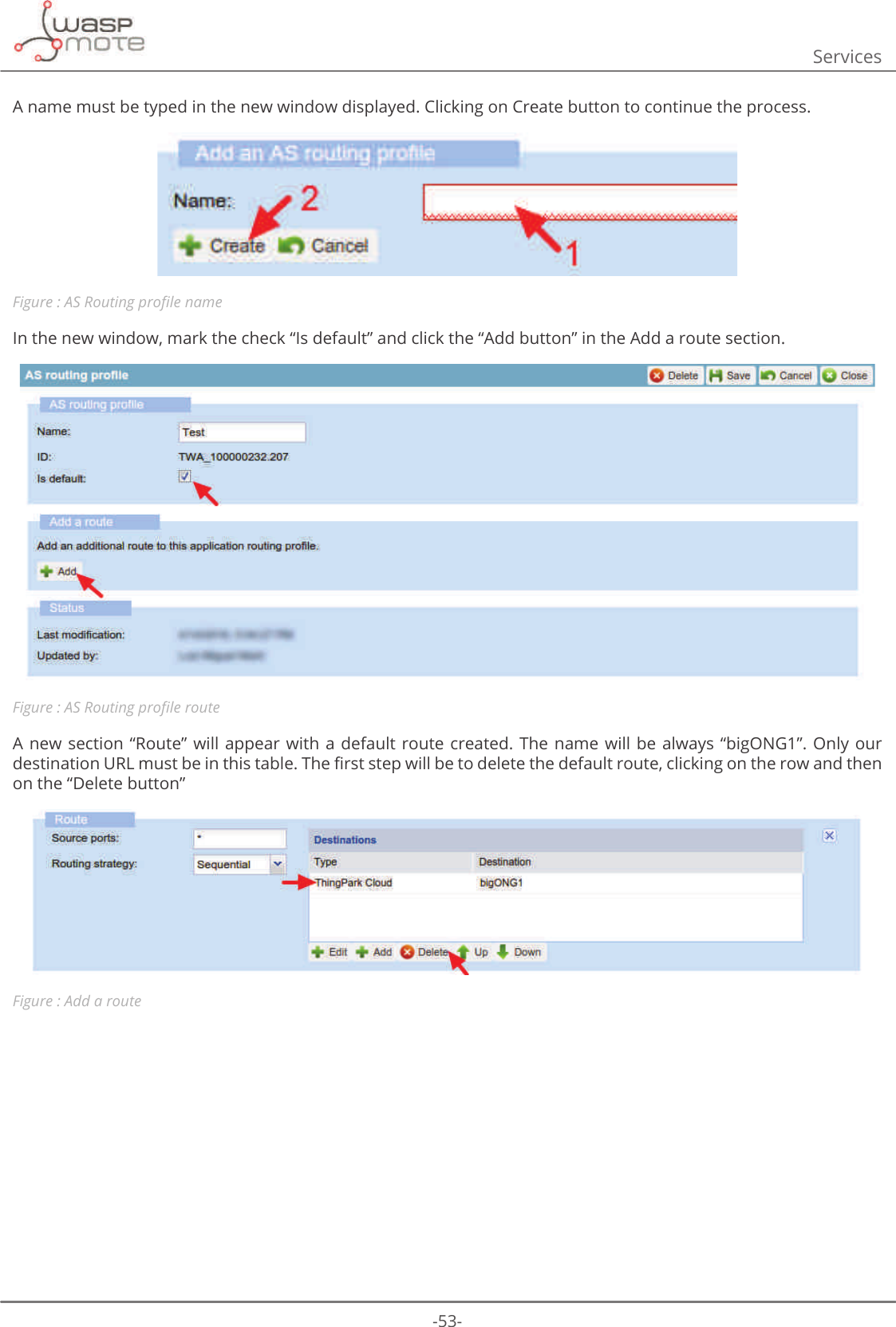
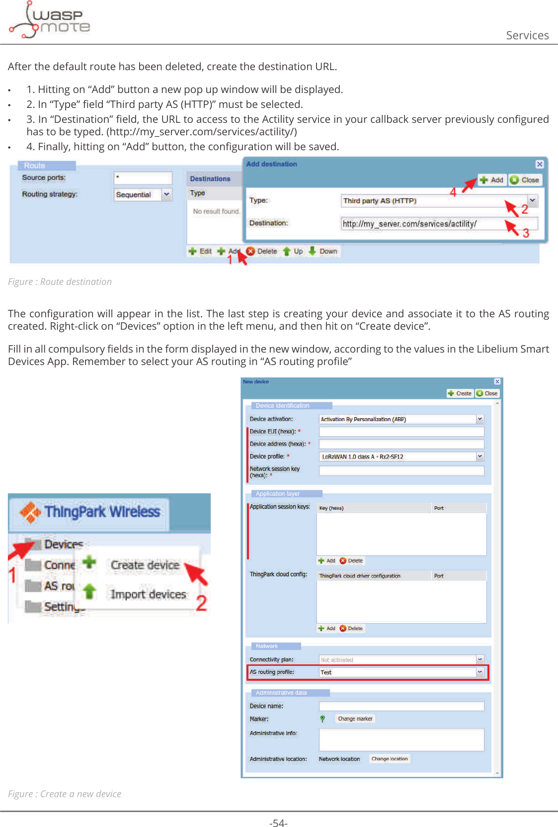
![-55-Services7RFKDQJHWKHQHWZRUNURXWLQJWRWKH$65RXWLQJSURȴOHVHOHFWDGHYLFHIURPWKHOLVWDQGKLWRQȊ(GLWȋEXWWRQ7KHQclick on Network section in the left menu.Figure : Steps to follow when the device is createdΖQ WKH Ȋ1HWZRUNFORXG URXWLQJȋ VHFWLRQ WKH QHZ $6 5RXWLQJ SURȴOH FUHDWHG PXVW EH VHOHFWHG FOLFNLQJ RQ WKHȊ&KDQJHȋEXWWRQVHOHFWWKHSURȴOHFUHDWHGIURPWKHGURSGRZQER[GLVSOD\HGLQWKHQHZSRSXSZLQGRZ)LQDOO\click on the “Save” button. Figure : Select the AS Routing created12.4.2. 6HUYHUFRQȴJXUDWLRQΖQWKHFDOOEDFNVHUYHUSUHYLRXVO\LQVWDOOHGVRPHSDUDPHWHUVPXVWEHFRQȴJXUHGWRHQDEOHWKHFRPPXQLFDWLRQwith the node.7KHVHUYLFHVLQLȴOHORFDWHGLQGDWDIROGHUKDVWREHXSGDWHGZLWKWKHIROORZLQJLQIRUPDWLRQLQWKHDFWLOLW\VHFWLRQ[actility]ORJBOHYHO ߙ$//ߚORJBࢱOH ߙORJVDFWLOLW\ORJߚVHUYHUBXUO ߙKWWSOUFWKLQJSDUNFRPVHQVRUߚ •log_level: This level is the minimum level to save logs in the system. Users can select one among these levels: -OFF: This option deactivate the log. -ERROR : It only reports ERROR messages. -INFO: It reports ERROR + INFO messages. -DEBUG: it reports ERROR + INFO + DEBUG messages. -ALL: It reports everything happened in the process. •ORJBȴOH The relative path where the log messages will be saved. •server_url: The downlink URL that Actility gives to send information from the server to the node. This URL will be the address of the primary Actility LRC cluster.](https://usermanual.wiki/Libelium-Comunicaciones-Distribuidas-S-L/PARKING-V1/User-Guide-3452582-Page-55.png)
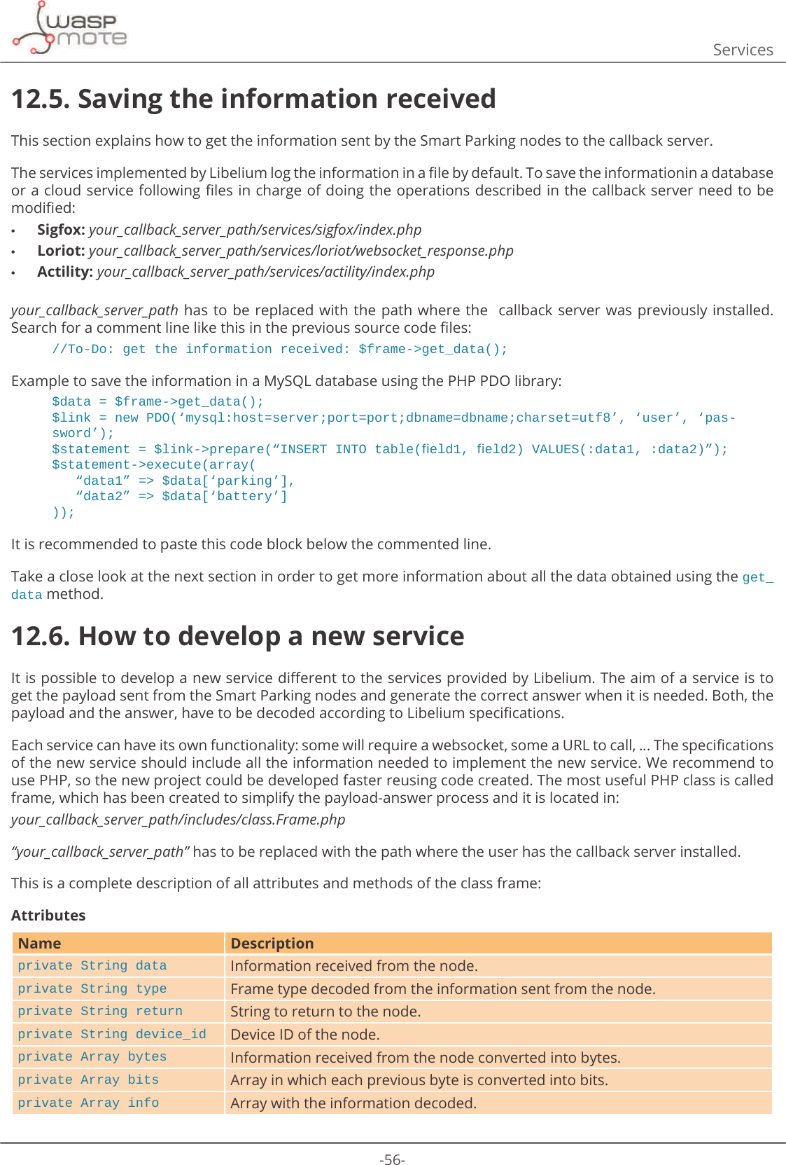
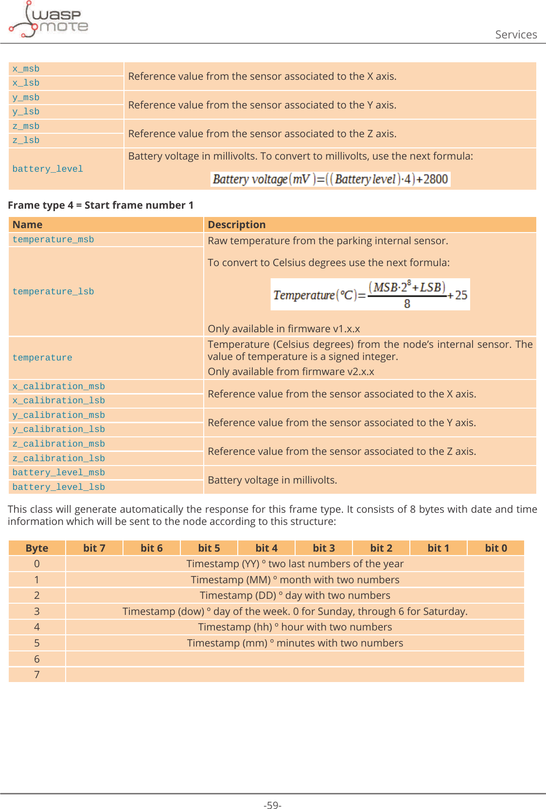
![-57-ServicesMethodsName Descriptionvoid __construct (String device_ID)Class constructor.Device ID has to be sent as a parameter. It will be saved in the attribute device_id.void reset (void) Reset all attributes.void get_info (String data)Decode the information received from the node and store it in the attribute info.The information received from the node has to be sent as a parameter.The information decoded will be saved in the attribute info.Boolean waiting_response(void) It returns a boolean to know if it necessary to send a response for the frame received.String get_response(void) It returns a string to send to the node.Array get_data(void) It returns an array with all information decoded.Using the get_data method of this class, users will get an array with the decoded information received from the QRGH'DWDZLOOGHSHQGRQWKHIUDPHW\SHUHFHLYHG7KHVHȴYHSDUDPHWHUVDUHFRPPRQLQDOOIUDPHW\SHVName Descriptiondevice_id ID of the devicebattery Battery level. [0 = good charge level | 1 = little charge level]parking Status of the parking slot [0 = empty | 1 = occupied]frame_counter Counter of the frames received.frame_typeCounter of the frames received. [0 = Info frame | 1 = Keep-Alive frame | 2 = Daily update frame | 3 = Error frame | 4 = Start frame 1 | 5 = Start frame 2]And then, these are the parameters for each frame type:Frame type 0 = Info frameName Descriptiontemperature_msb Raw temperature from the parking internal sensor.To convert to Celsius degrees use the next formula: 2QO\DYDLODEOHLQȴUPZDUHY[[temperature_lsbtemperatureTemperature (Celsius degrees) from the node’s internal sensor. The value of temperature is a signed integer. 2QO\DYDLODEOHIURPȴUPZDUHY[[x_msb Reference value from the sensor associated to the X axis.x_lsby_msb Reference value from the sensor associated to the Y axis. y_lsbz_msb Reference value from the sensor associated to the Z axis. z_lsb](https://usermanual.wiki/Libelium-Comunicaciones-Distribuidas-S-L/PARKING-V1/User-Guide-3452582-Page-57.png)
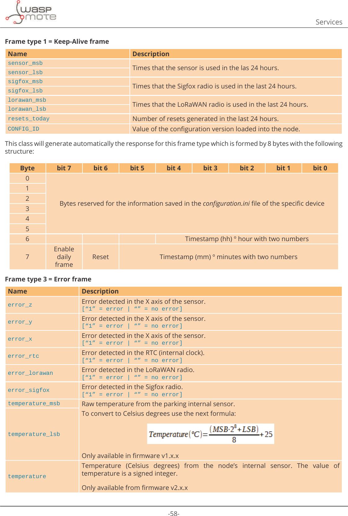
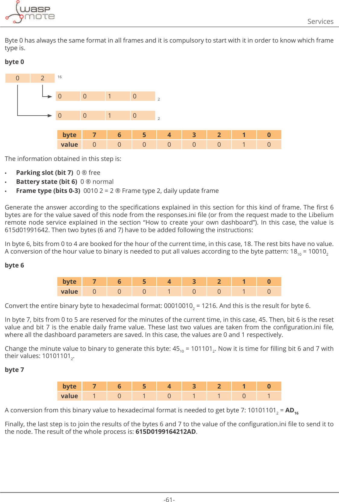
![-60-ServicesFrame type 5 = Start frame number 2Name Firmware version.CODE_ID Firmware version.NM_START Beginning hour of the night mode.NM_PERIOD Duration in hours of the night mode.NM_SLEEP_TIME Sleep time between consecutive sensor measurements (during night mode).NM_KEEP_ALIVE Elapsed time since last transmission to trigger a Keep-Alive frame (during night mode).RADIO_MODE Selected transmission mode between Sigfox, LoRaWAN y their combinations.SLEEP_TIME Sleep time between consecutive sensor measurements.KEEP_ALIVE Elapsed time since last transmission to trigger a Keep-Alive frame.THRESHOLD Threshold for detecting a vehicle over the parking slot.When using PHP as a programming language of the new service is not possible, using the raw information sent from the device will be mandatory.S. Frames section of this document explains how to do some operations to get the real value of every parameter received and how to generate the answer to sent it back to the Smart Parking node.Example Payload: 0400003f34b909173f600fc2 Node ID: 0102030405060708. Date: 13th February 2017 18:45:22. UHVSRQVHVLQLȴOHFRQWHQWUHVSRQVHIURPWKH/LEHOLXPUHPRWHQRGHVHUYLFH[devices] ߙGߚFRQȴJXUDWLRQLQLȴOHFRQWHQWYDOXHVVDYHGLQWKHZHEIRUP[0102030405060708]'(9,&(B1$0( ߙ6HWߚSLEEP_TIME = 1KEEP_ALIVE = 910B67$786 NM_PERIOD = 9NM_START = 22NM_SLEEP_TIME = 2NM_KEEP_ALIVE = 4THRESHOLD = 93BAT_READING = 0ENABLE_DAILY_FRAME = 1CONFIG_ID = 97RADIO_MODE = 0LORAWAN_MODE = 05(6(7B5(48(67 Following the Frame section, we have 12 bytes (v1.x.x). Each byte is formed with two numbers, starting from the left. The result is:byte 0 1 2 3 4 5 6 7 8 9 10 11value 04 00 00 3f 34 b9 09 17 3f 60 0f c2](https://usermanual.wiki/Libelium-Comunicaciones-Distribuidas-S-L/PARKING-V1/User-Guide-3452582-Page-60.png)