Logpro K114 10mW 915MHz FHSS wireless transceiver User Manual Manual

Logpro Limited 10mW 915MHz FHSS wireless transceiver Manual

Manual

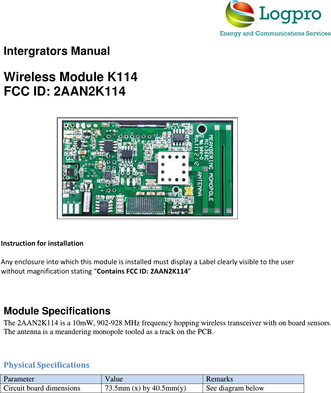
Intergrators Manual  Wireless Module K114 FCC ID: 2AAN2K114                        Module Specifications The 2AAN2K114 is a 10mW, 902-928 MHz frequency hopping wireless transceiver with on board sensors. The antenna is a meandering monopole tooled as a track on the PCB.   Physical Specifications Parameter  Value  Remarks Circuit board dimensions  73.5mm (x) by 40.5mm(y)  See diagram below      Instruction for installation  Any enclosure into which this module is installed must display a Label clearly visible to the user without magnification stating “Contains FCC ID: 2AAN2K114”    Logpro Energy and Communications Services
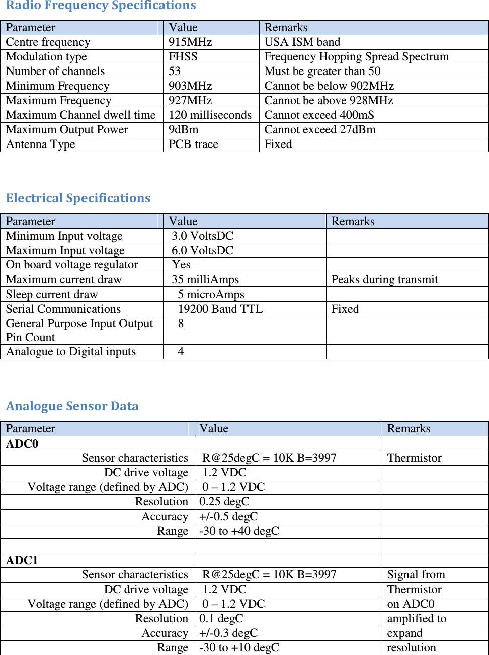
 Radio Frequency Specifications Parameter  Value  Remarks Centre frequency  915MHz  USA ISM band Modulation type  FHSS  Frequency Hopping Spread Spectrum Number of channels  53  Must be greater than 50 Minimum Frequency  903MHz  Cannot be below 902MHz Maximum Frequency  927MHz  Cannot be above 928MHz Maximum Channel dwell time  120 milliseconds  Cannot exceed 400mS Maximum Output Power  9dBm  Cannot exceed 27dBm Antenna Type  PCB trace  Fixed   Electrical Specifications Parameter  Value  Remarks Minimum Input voltage   3.0 VoltsDC    Maximum Input voltage   6.0 VoltsDC    On board voltage regulator   Yes   Maximum current draw   35 milliAmps  Peaks during transmit Sleep current draw     5 microAmps   Serial Communications     19200 Baud TTL  Fixed General Purpose Input Output Pin Count    8   Analogue to Digital inputs     4     Analogue Sensor Data Parameter  Value  Remarks ADC0     Sensor characteristics  R@25degC = 10K B=3997  Thermistor DC drive voltage  1.2 VDC   Voltage range (defined by ADC)  0 – 1.2 VDC   Resolution 0.25 degC   Accuracy +/-0.5 degC   Range -30 to +40 degC       ADC1     Sensor characteristics  R@25degC = 10K B=3997  Signal from DC drive voltage  1.2 VDC  Thermistor Voltage range (defined by ADC)  0 – 1.2 VDC  on ADC0 Resolution 0.1 degC  amplified to Accuracy +/-0.3 degC  expand  Range -30 to +10 degC  resolution
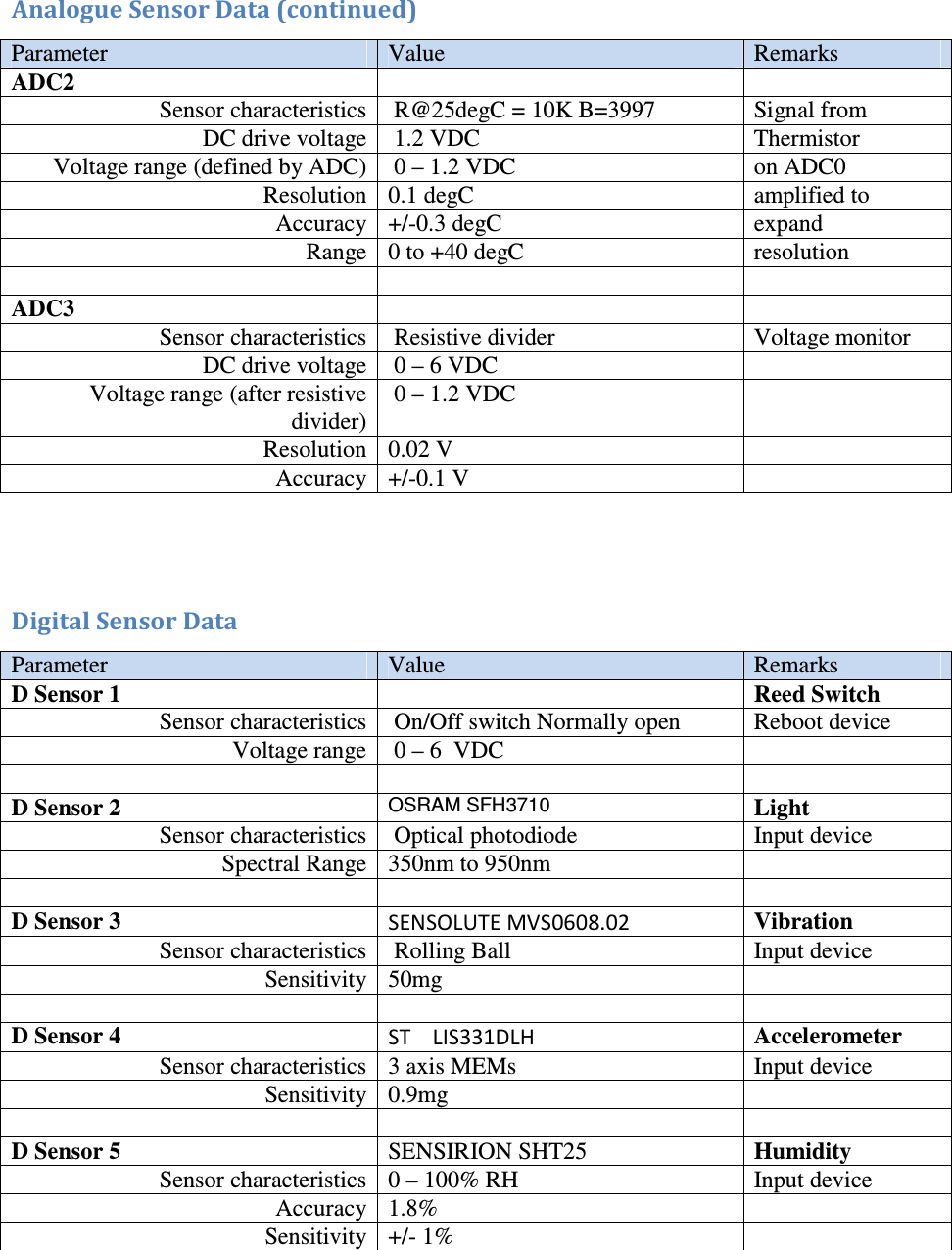
 Analogue Sensor Data (continued) Parameter  Value  Remarks ADC2     Sensor characteristics  R@25degC = 10K B=3997  Signal from DC drive voltage  1.2 VDC  Thermistor Voltage range (defined by ADC)  0 – 1.2 VDC  on ADC0 Resolution 0.1 degC  amplified to Accuracy +/-0.3 degC  expand  Range 0 to +40 degC  resolution     ADC3     Sensor characteristics  Resistive divider  Voltage monitor DC drive voltage  0 – 6 VDC   Voltage range (after resistive divider)  0 – 1.2 VDC   Resolution 0.02 V   Accuracy +/-0.1 V     Digital Sensor Data Parameter  Value  Remarks D Sensor 1    Reed Switch Sensor characteristics  On/Off switch Normally open  Reboot device Voltage range   0 – 6  VDC       D Sensor 2 OSRAM SFH3710 Light Sensor characteristics  Optical photodiode  Input device Spectral Range  350nm to 950nm       D Sensor 3  SENSOLUTE MVS0608.02 Vibration Sensor characteristics  Rolling Ball  Input device Sensitivity  50mg       D Sensor 4  ST    LIS331DLH  Accelerometer Sensor characteristics 3 axis MEMs  Input device Sensitivity  0.9mg       D Sensor 5  SENSIRION SHT25 Humidity Sensor characteristics 0 – 100% RH  Input device Accuracy 1.8%   Sensitivity  +/- 1%
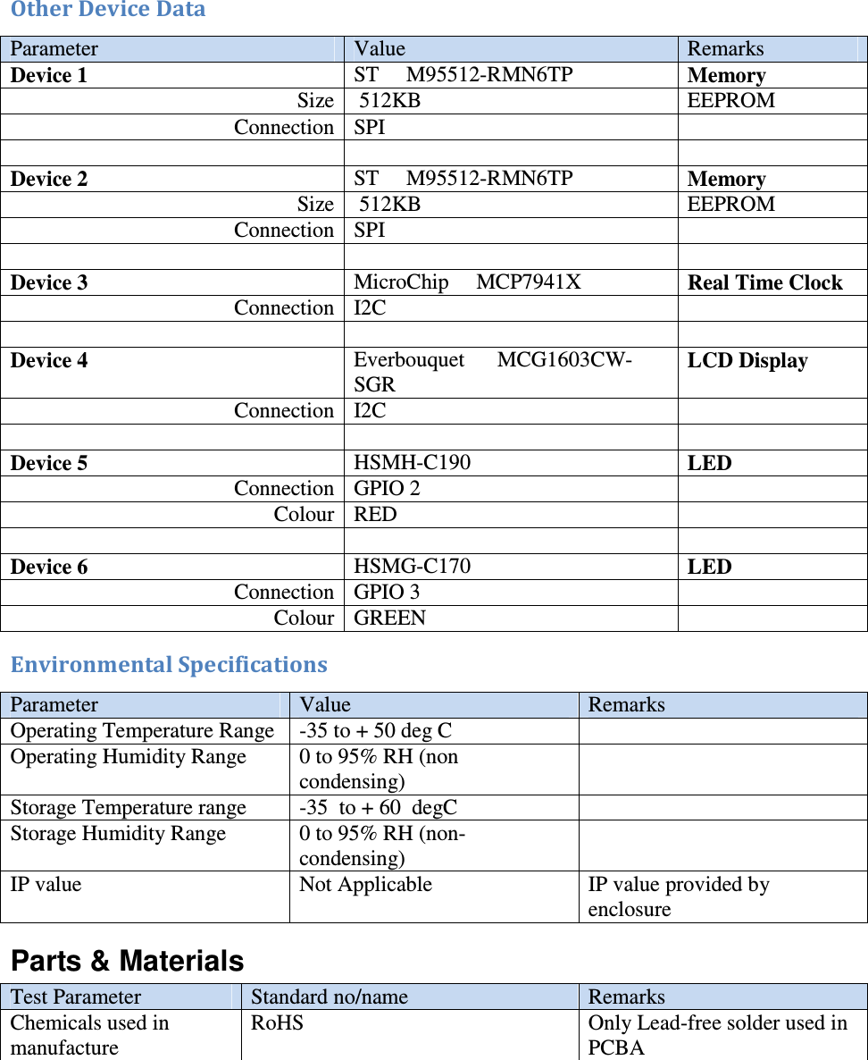
 Other Device Data Parameter  Value  Remarks Device 1 ST     M95512-RMN6TP  Memory Size  512KB  EEPROM Connection SPI        Device 2 ST     M95512-RMN6TP  Memory Size  512KB  EEPROM Connection SPI       Device 3 MicroChip     MCP7941X  Real Time Clock Connection I2C       Device 4 Everbouquet      MCG1603CW-SGR LCD Display Connection I2C       Device 5 HSMH-C190  LED      Connection GPIO 2   Colour RED      Device 6 HSMG-C170  LED      Connection GPIO 3   Colour GREEN   Environmental Specifications Parameter  Value  Remarks Operating Temperature Range  -35 to + 50 deg C   Operating Humidity Range   0 to 95% RH (non condensing)  Storage Temperature range  -35  to + 60  degC   Storage Humidity Range  0 to 95% RH (non-condensing)  IP value  Not Applicable  IP value provided by enclosure Parts & Materials Test Parameter  Standard no/name  Remarks Chemicals used in manufacture RoHS  Only Lead-free solder used in PCBA
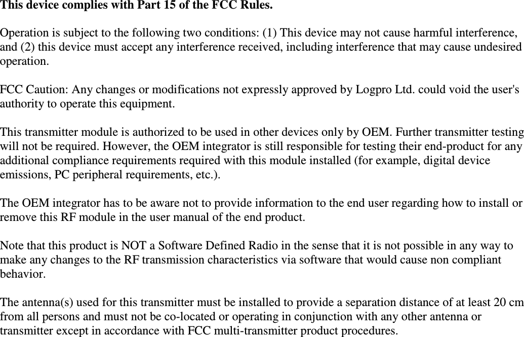
   This device complies with Part 15 of the FCC Rules.   Operation is subject to the following two conditions: (1) This device may not cause harmful interference, and (2) this device must accept any interference received, including interference that may cause undesired operation.  FCC Caution: Any changes or modifications not expressly approved by Logpro Ltd. could void the user's authority to operate this equipment.  This transmitter module is authorized to be used in other devices only by OEM. Further transmitter testing will not be required. However, the OEM integrator is still responsible for testing their end-product for any additional compliance requirements required with this module installed (for example, digital device emissions, PC peripheral requirements, etc.).  The OEM integrator has to be aware not to provide information to the end user regarding how to install or remove this RF module in the user manual of the end product.  Note that this product is NOT a Software Defined Radio in the sense that it is not possible in any way to make any changes to the RF transmission characteristics via software that would cause non compliant behavior.  The antenna(s) used for this transmitter must be installed to provide a separation distance of at least 20 cm from all persons and must not be co-located or operating in conjunction with any other antenna or transmitter except in accordance with FCC multi-transmitter product procedures.

Navigation menu