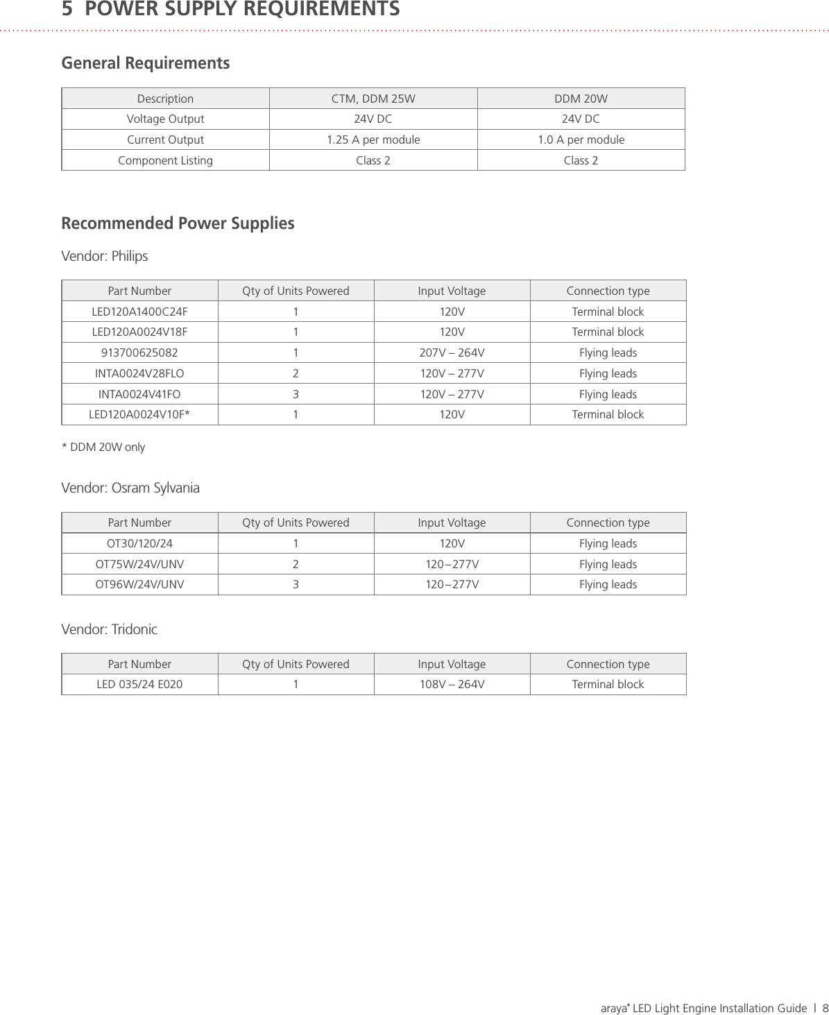
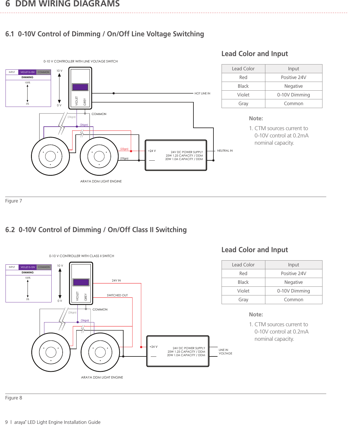
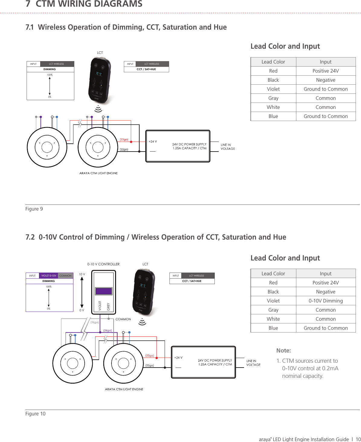
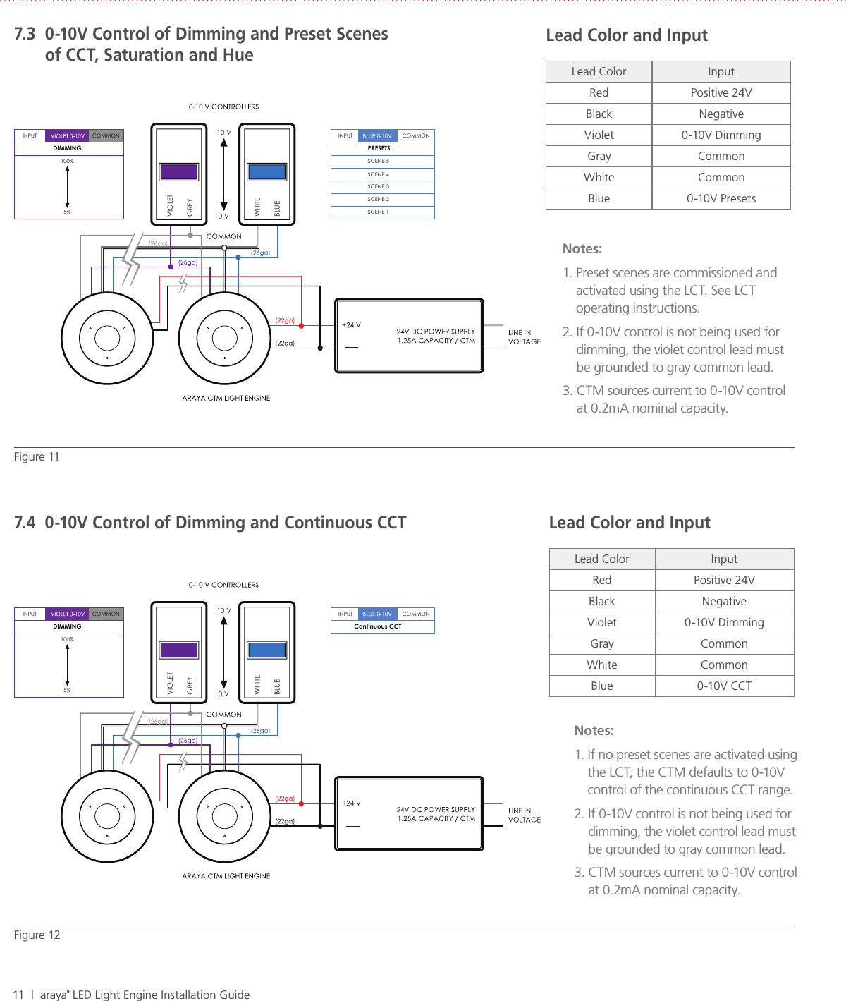
Lumenetix CTM0-DDM0 Color Tuning Module User Manual

Lumenetix Inc Color Tuning Module Users Manual

Users Manual

THE TRUE AND PERFECT LIGHTaraya® LED Light Engine  CTM0 32  CTM0 19  CTM0 12 DDM0 32  DDM0 19  DDM0 12Installation Guide
iii  |  araya® LED Light Engine Installation GuideTABLE OF CONTENTS1  Introduction  22  Heat Sinking  32.1  Compatible Heat Sinks2.2  Mechanical Attachment of the Heat Sink3  CTM Case Temperature Measurement  54  Secondary Optics   64.1  CTM0 12 Reflectors4.2  DDM0 19 Reflectors4.2.1 Attaching Reflectors4.2.2 Compatible Reflectors5  Power Supplies  86  DDM Wiring Diagrams  96.1  0-10V Control of Dimming / On/Off Line Voltage Switching6.2  0-10V Control of Dimming / On/Off Class II Switching7  CTM Wiring Diagrams  107.1  Wireless Operation of Dimming, CCT, Saturation and Hue7.2  0-10V Control of Dimming / Wireless Operation of CCT, Saturation and Hue7.3  0-10V Control of Dimming and Preset Scenes of CCT, Saturation and Hue7.4  0-10V Control of Dimming and Continuous CCT
araya® LED Light Engine Installation Guide  |  2This Installation Guide covers the following araya® Color Tuning Modules (CTM) and Dynamic Dimming Modules™ (DDM)CTM0 32  •  DDM0 32CTM0 19  •  DDM0 19CTM0 12  •  DDM0 12For complete Color Tuning Module specifications, please visit: www.lumenetix.com/downloadsThis Installation Guide covers heat sinking, case temperature measurement, secondary optics, power supply and wiring diagrams for wireless operation using the Lumenetix Light Commissioning Tool, industry standard 0-10V wired controls or a hybrid operation that combines hard wired and wireless control. The CTM Source diffuser is fragile. Avoid touching the diffuser  during handling and assembly.Do not operate the CTM while it is resting face down against  a table or other solid surface.For long term, reliable operation, proper heat sinking is critical.1  INTRODUCTION
3  |  araya® LED Light Engine Installation Guide2  HEATSINKINGThe CTM light module requires an external heat sink in order to ensure proper operating temperature of the LEDs. The CTM has a conductive aluminum case and an efficient thermal path to the LED array. These features promote efficient thermal management and allow for a simple heat sink design in most applications.Examples of heat sinking methods are: cast or extruded heat sinks, an aluminum panel or aluminum fixture housing. Both carbon and stainless steel are much less efficient at transferring heat than aluminum and therefore are not recommended as heat sink material. The heat sink mounting surface should be flat and smooth. Metal-to-metal contact surfaces will result in best performance; anodized or unfinished mounting surfaces are recommended. Mounting the CTM on a painted aluminum surface will reduce the performance of the heat sink material.2.1  Compatible Heat SinksThe following tables list heat sinks models that have compatible form factors and thermal resistance characteristics for use  with the CTM. The thermal resistances assume an approximate ambient temperature of 25C. The heat sinks listed here  are suggestions only. The heat sink must be evaluated and temperature tested in the fixture application at applicable  ambient temperatures.MechaTronix (round)Part Number Dia. (mm) Height (mm) Thermal Resistance (°C/W)LSB9950 99 50 1.3 – 1.5LSB9980 99 80 1.2 – 1.4Additional product information at www.led-heatsink.comNuventix (round)Part Number Description Input Voltage Dia. (mm) Height (mm) Thermal Resistance (°C/W)HP30S-CALBL-001 Heat Sink  95 39 2.5 (heat sink only)SPARS-CM005-002 (1) Cooler 5V 1.0 – 1.55SPARS-CM012- 002 (1) Cooler 12V 1.0 – 1.55Additional product information at www.nuventix.comNo current commercial 24V power supply offerings with dual voltage out for Nuventix Synjet cooler (24V out w/ 5V or 12V out).  Requires DC/DC voltage adaptor without dual voltage output.Aavid Thermalloy Heat Sink Extrusions (square/rectangular)Part Number Width (mm) Length Height (mm) Thermal Resistance (°C/W)67590 88 88 31 1.5 – 1.761085 136 85 33 1.4 – 1.6Additional product information at www.aavid.com
araya® LED Light Engine Installation Guide  |  42.2  Mechanical Attachment of the Heat SinkThe CTM/DDM light engine has two options for heat sink mounting: 1.  Front mount using four 4-40 or M2.5 screws 2.  Rear mount using three M3 screwsFigure 1: Rear Mount of CTM/DDM to Heat Sink81mm3.2in4X FRONT MOUNT3.10mm.12in(FOR 4-40 UNCOR M2.5 SCREWS) 90°  90°  77°  44°  46° 70.53mm2.78in B.C. 31°  61° DIMMING LEADS: 1 PURPLE, 1 GREY, 24 GACCT LEADS: 1 BLUE, 1 WHITE, 24 GA (NOT USED ON DDM)610mm (24in) LONG, 6mm (.25in) STRIP LENGTHPOWER LEADS: 1 RED, 1 BLACK, 22 GA610mm (24in) LONG, 6mm (.25in) STRIP LENGTH 22mm.85in 3X M3mm.12inx0.55mm (.2in)REAR MOUNT 3X 120° POWER LEAD PORTCONTROL LEAD PORTRESERVED FOR FUTURE USE
5  |  araya® LED Light Engine Installation GuideThe thermal management characteristics of the heat sink used with the CTM should be validated by measuring its case temperature.  This test should be done with the CTM installed in the fixture at ambient temperature and air flow conditions similar to the end-use installation. araya® CTMs are available with two ranges: 1600 – 4000K and 2700 – 6000K. The power draw of the CTM varies by approximately one watt over the CCT range with peak power draw occurring at the CCT shown in the following table. Depending on the CCT range, the case temperature should be measured at the following CCT setting.CCT Setting for Case Temperature MeasurementCTM CCT range CCT Setting to Measure Tcase1600 –  4000K 2800K2800 –  6000K 4400KThe proper case temperature measurement location is next to the exit for the power leads, see Figure 3. The temperature reading should be made after the unit has reached steady state, where the case temperature levels out. It is recommended to design for a case temperature of 70° C at maximum ambient temperature conditions The CTM color tuning module has built-in over-temperature protection. It is designed to turn down the current to the LED array when the case temperature reaches 75° C. This ensures the LEDs don’t exceed their maximum rated temperature.3  CTM CASE TEMPERATURE MEASUREMENTFigure 2: Case Temperature Measurement Point
araya® LED Light Engine Installation Guide  |  64.1  CTM0 12 ReflectorsThe CTM0 12 accepts the Lumenetix sReflector and mReflectors and has attachment features to accept other reflectors. 4  SECONDARY OPTICS Figure 4: Side Mount Attachment of the sReflector and the mReflectorFigure 3: CTM0 12 Front Attaching ReflectorsNOTE: mReflector shown, assembly similar for sReflectorREFLECTORM1.8THREAD FORMINGSOURCE APERTURE5 mm (0.187")Reflector Type Fastener SpecificationsReflector 0 – 80 x ¼" FlatheadmReflector M1.8 x 6 Thread Forming Flathead
7  |  araya® LED Light Engine Installation Guide4.2  CTM0 19 Reflectors4.2.1  Attaching ReflectorsThe CTM0 19 accepts the twist-to-lock reflectors with an attachment collar. The module also has provisions for front mount reflectors. The fastener specifications are shown in the following table while mounting hole locations are shown in Figures 6 & 7.CTM0 19 Secondary Optics Fastener SpecificationsCTM0 19 Reflector Fastener specifications Screw lengthTwist Lock w/ Collar 2 - 28 x 3/16, M1.8 x 5 5 mm (3/16")Front Mount 2 - 28, M1.8 5 mm (3/16") or 10 mm (3/8")M1.8 x 5, 2 - 28 x 3/16THREAD FORMINGUSE FLAT HEAD SCREWS REFLECTORSOURCE APERTUREREFLECTOR5 mm (0.187")10 mm (0.375")SOURCE APERTURE2 - 28 OR M1.8THREAD FORMING Figure 5: CTM0 19 Twist-Lock Style Reflectors with attachment collars Figure 6: CTM0 19 Front Attaching Reflectors 4.2.2  Compatible ReflectorsCTM0 19 Compatible Twist-Lock ReflectorsVendor:  Diffractive Optics, www.diffractive-optics.com Part Number Beam Angle (degrees)P6680 40P6645 60P7879 40P6764 60CTM0 19 Compatible Front Mount ReflectorsVendor: Alux-Luxar, www.alux-luxar.comPart Number Beam Angle (degrees)XLC 400 28XLC 500 26XLC 800 42XLC 110 0 27XLC 1300 22XLC 1400 25XLC 1500 53
araya® LED Light Engine Installation Guide  |  8Recommended Power SuppliesVendor: PhilipsPart Number Qty of Units Powered Input Voltage Connection typeLED120A1400C24F 1120V Terminal blockLED120A0024V18F 1120V Terminal block913700625082 1 207V – 264V Flying leadsINTA0024V28FLO 2 120V – 277V Flying leadsINTA0024V41FO 3 120V – 277V Flying leadsLED120A0024V10F* 1120V Terminal block* DDM 20W onlyVendor: Osram SylvaniaPart Number Qty of Units Powered Input Voltage Connection typeOT30/120/24 1120V Flying leadsOT75W/24V/UNV 2120 – 277V Flying leadsOT96W/24V/UNV 3120 – 277V Flying leadsVendor: TridonicPart Number Qty of Units Powered Input Voltage Connection typeLED 035/24 E020 1 108V – 264V Terminal blockGeneral RequirementsDescription CTM, DDM 25W DDM 20WVoltage Output 24V DC 24V DCCurrent Output 1.25 A per module 1.0 A per moduleComponent Listing Class 2 Class 25  POWER SUPPLY REQUIREMENTS
9  |  araya® LED Light Engine Installation GuideINPUT10 V0 VVIOLETGREYCOMMONDIMMING100%5%0-10 V CONTROLLER WITH LINE VOLTAGE SWITCHARAYA DDM LIGHT ENGINE24V DC POWER SUPPLY25W 1.25 CAPACITY / DDM20W 1.0A CAPACITY / DDMNEUTRAL INHOT LINE ININPUT10 V0 VVIOLETGREYCOMMONDIMMING100%5%0-10 V CONTROLLER WITH CLASS II SWITCHARAYA DDM LIGHT ENGINE24V DC POWER SUPPLY25W 1.25 CAPACITY / DDM20W 1.0A CAPACITY / DDMLINE IN VOLTAGE24V INSWITCHED OUTLead Color and InputLead Color InputRed Positive 24VBlack NegativeViolet 0-10V DimmingGray CommonLead Color and InputLead Color InputRed Positive 24VBlack NegativeViolet 0-10V DimmingGray Common6  DDM WIRING DIAGRAMSFigure 7Figure 86.1  0-10V Control of Dimming / On/Off Line Voltage Switching6.2  0-10V Control of Dimming / On/Off Class II SwitchingNote:1.  CTM sources current to 0-10V control at 0.2mA nominal capacity.Note:1.  CTM sources current to 0-10V control at 0.2mA nominal capacity.
araya® LED Light Engine Installation Guide  |  10INPUTINPUTCCT / SAT+HUEDIMMING100%5% LCTLCT WIRELESSLCT WIRELESSINPUTINPUT10 V0 VVIOLETGREYCCT / SAT+HUECOMMONDIMMING100%5%0-10 V CONTROLLER LCTLCT WIRELESSLead Color and InputLead Color InputRed Positive 24VBlack NegativeViolet Ground to CommonGray CommonWhite CommonBlue Ground to CommonLead Color and InputLead Color InputRed Positive 24VBlack NegativeViolet 0-10V DimmingGray CommonWhite CommonBlue Ground to Common7  CTM WIRING DIAGRAMSFigure 97.1  Wireless Operation of Dimming, CCT, Saturation and HueFigure 107.2  0-10V Control of Dimming / Wireless Operation of CCT, Saturation and HueNote:1.  CTM sources current to 0-10V control at 0.2mA nominal capacity.
11  |  araya® LED Light Engine Installation GuideCOMMONINPUTINPUT 10 V0 VVIOLETGREYWHITEBLUEPRESETSSCENE 5SCENE 4SCENE 3SCENE 2SCENE 1COMMONDIMMING100%5%COMMONINPUTINPUT 10 V0 VVIOLETGREYWHITEBLUEContinuous CCTCOMMONDIMMING100%5%Fig ure 11Figure 127.3   0-10V Control of Dimming and Preset Scenes  of CCT, Saturation and Hue7.4  0-10V Control of Dimming and Continuous CCTNotes:1.  Preset scenes are commissioned and activated using the LCT. See LCT operating instructions.2.  If 0-10V control is not being used for dimming, the violet control lead must be grounded to gray common lead.3.  CTM sources current to 0-10V control at 0.2mA nominal capacity.Notes:1.  If no preset scenes are activated using the LCT, the CTM defaults to 0-10V control of the continuous CCT range.2.  If 0-10V control is not being used for dimming, the violet control lead must be grounded to gray common lead.3.  CTM sources current to 0-10V control at 0.2mA nominal capacity.Lead Color and InputLead Color InputRed Positive 24VBlack NegativeViolet 0-10V DimmingGray CommonWhite CommonBlue 0-10V PresetsLead Color and InputLead Color InputRed Positive 24VBlack NegativeViolet 0-10V DimmingGray CommonWhite CommonBlue 0-10V CCT
Lumenetix Inc.4742 Scotts Valley DriveScotts Valley CA 9506687 7.8 05 .728 4www.lumenetix.comRevised 01.24.14Specifications subject to change without notice

Navigation menu