METRA INZENIRING D O O 0003P1142 Electronic Lock RFID ISO ST User Manual
METRA INZENIRING D.O.O Electronic Lock RFID ISO ST
UserManual.wiki
>
METRA INZENIRING D O O
>
0003P1142 User Manual
User Manual
Navigation menu
Upload a User Manual
Namespaces
Wiki Guide
HTML
PDF
Info
Views
User Manual
Discussion / Help
Navigation
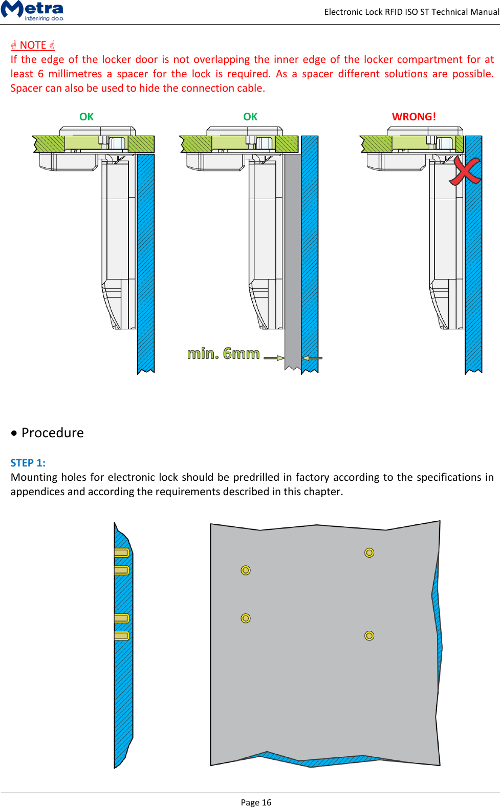
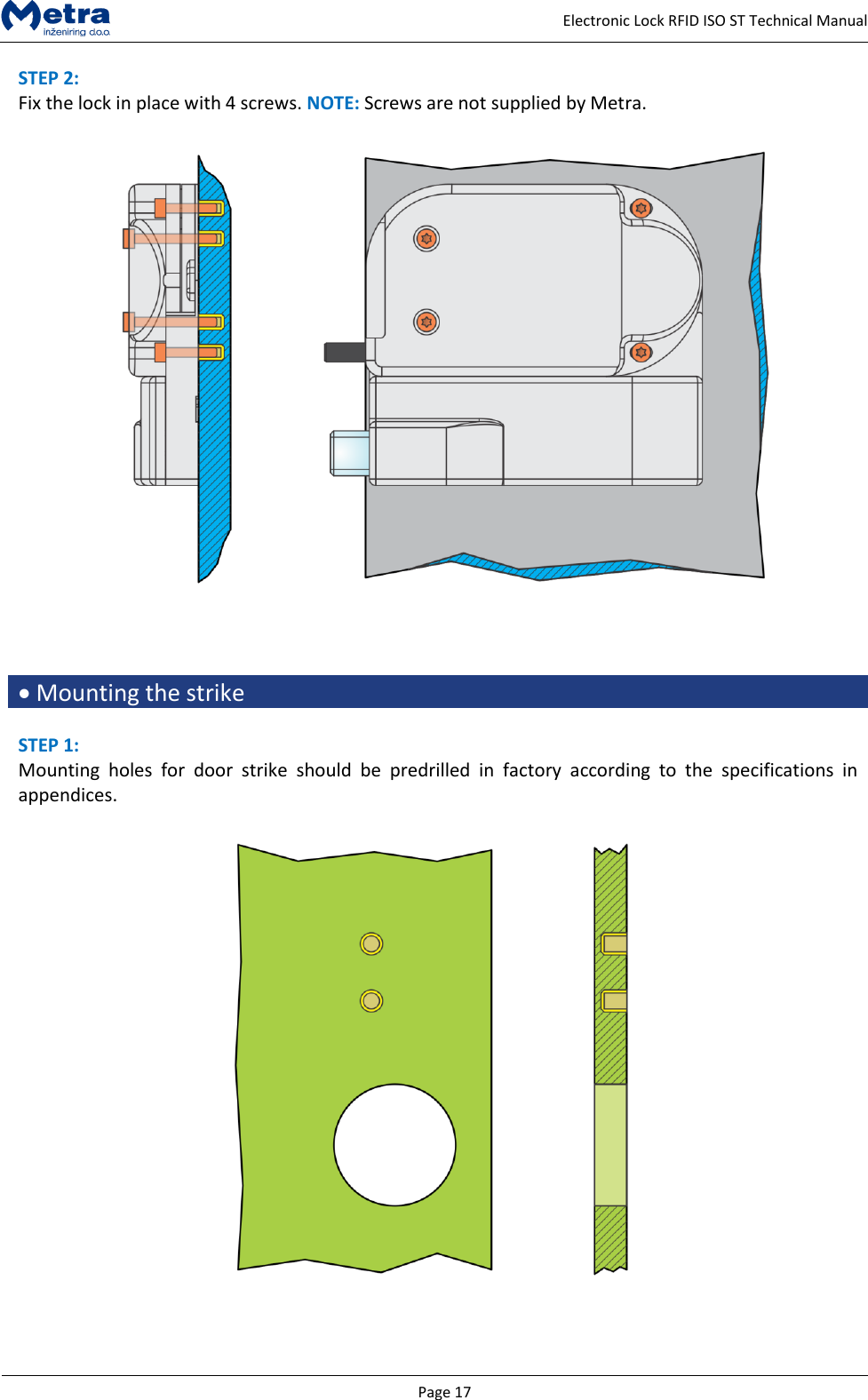
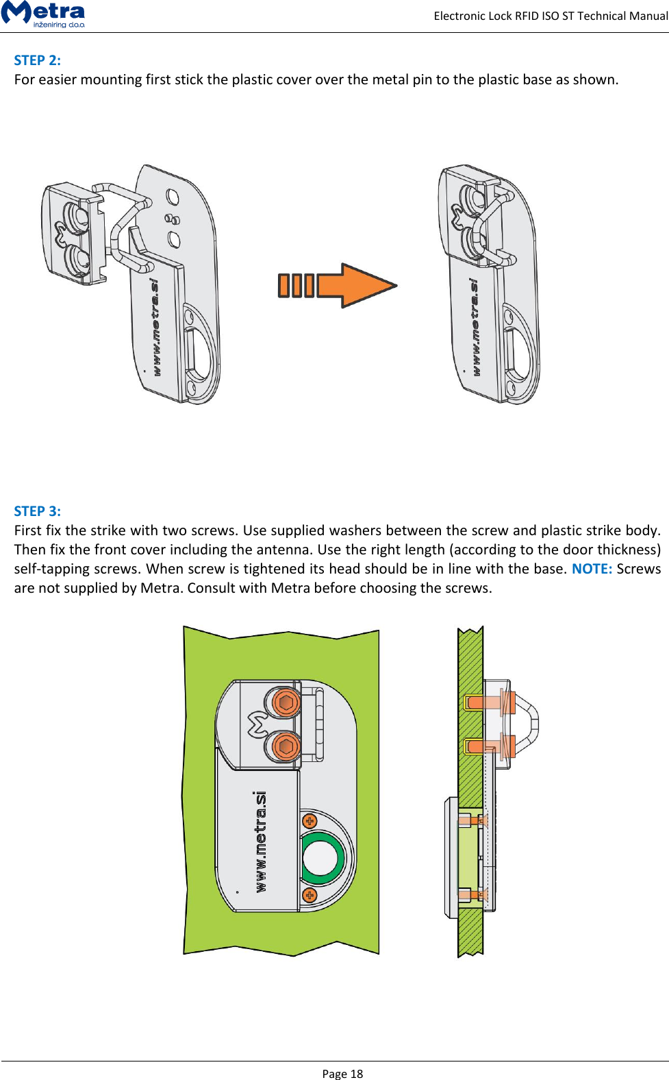
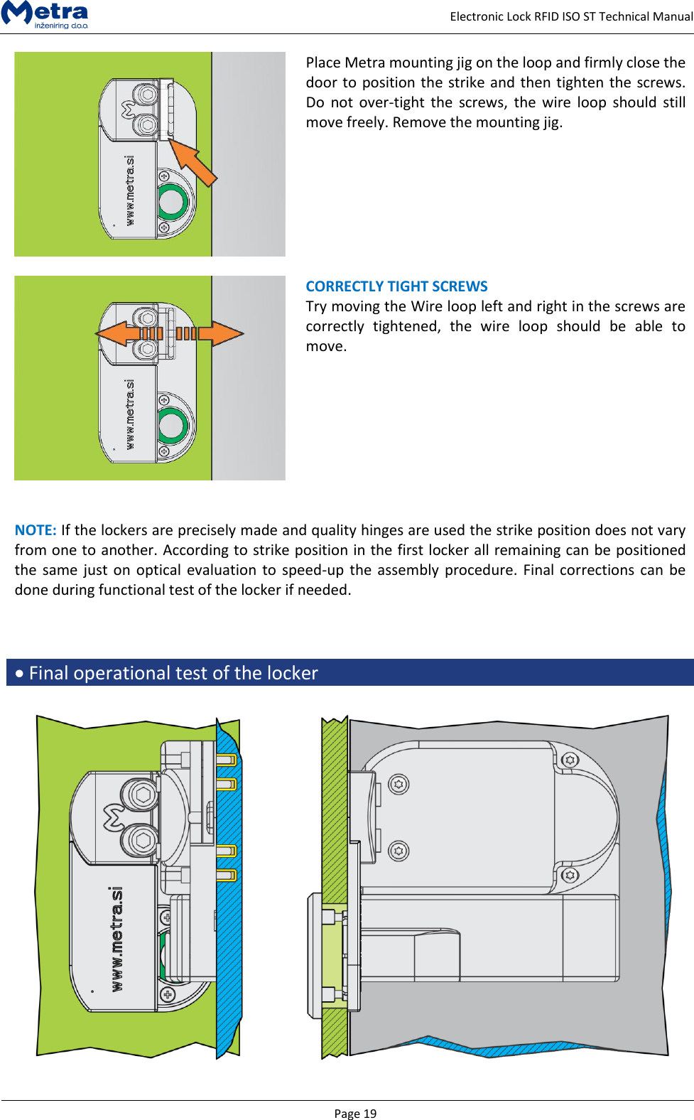
![Page 3 Electronic Lock RFID ISO ST Technical Manual Electronic Lock RFID ISO ST Technical Manual Manufacturer: Metra inženiring d.o.o. IOC Trzin Špruha 19 SI-1236 Trzin, Slovenia phone: fax: web: +386 1 56 10 740 +386 1 56 10 744 www.metra.si Trade Mark: Metra MEW System Model/Type ref.: Electronic Lock RFID ISO ST Part Number: 1142 FCC ID: 2ABT80003P1142 Year of Construction: 2015 This product is in conformity with the essential requirements and other relevant requirements of the following EU Directives: Radio and Telecommunications Terminal Equipment (R&TTE) Directive 2014/53/EU RoHS Recast (RoHS2) Directive 2011/65/EU of the European Parliament and of the Council on the restriction of the use of certain hazardous substances in electrical and electronics equipment. Low Voltage Directive (LVD) 2014/35/EU that ensures that electrical equipment within certain voltage limits provides a high level of protection for European citizens. Model/Type ref.: Electronic Lock RFID ISO ST Part Number: 1142 FCC ID: 2ABT80003P1142 This device complies with part 15 of the FCC Rules. Operation is subject to the following two conditions: (1) This device may not cause harmful interference, and (2) this device must accept any interference received, including interference that may cause undesired operation. This device has been tested and found to comply with the limits for a Class B digital device, pursuant to Part 15 of the FCC Rules. These limits are designed to provide reasonable protection against harmful interference in a residential installation. This equipment generates uses and can radiate radio frequency energy and, if not installed and used in accordance with the instructions, may cause harmful interference to radio communications. However, there is no guarantee that interference will not occur in a particular installation. If this equipment does cause harmful interference to radio or television reception, which can be determined by turning the equipment off and on, the user is encouraged to try to correct the interference by one or more of the following measures: Reorient or relocate the receiving antenna. Increase the separation between the equipment and receiver. Connect the equipment into an outlet on a circuit different from that to which the receiver is connected. Consult the dealer or an experienced radio/TV technician for help. Electronic Lock RFID ISO ST Technical Manual [rev.3-080316] 2016 Metra inženiring d.o.o. All Rights reserved. No part of this manual may be reproduced in any form or by any means without prior written permission of Metra inženiring d.o.o. The contents of this manual are subject to change without notice. All efforts have been made to ensure the accuracy of the contents of this manual, however, should any errors be detected, Metra inženiring would greatly appreciate being informed of them. Metra inženiring d.o.o. can assume no responsibility for any errors in this manual.](https://usermanual.wiki/METRA-INZENIRING-D-O-O/0003P1142/User-Guide-2926426-Page-3.png)