Marine Data Systems MIV30 Shipboum Automatic Identification System (AIS) User Manual MIV installation manual rev11g
Marine Data Systems Shipboum Automatic Identification System (AIS) MIV installation manual rev11g
UserManual.wiki
>
Marine Data Systems
>
MIV30 User Manual
Installation Manual
Navigation menu
Upload a User Manual
Namespaces
Wiki Guide
HTML
PDF
Info
Views
User Manual
Discussion / Help
Navigation


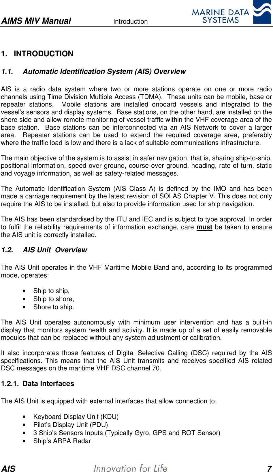
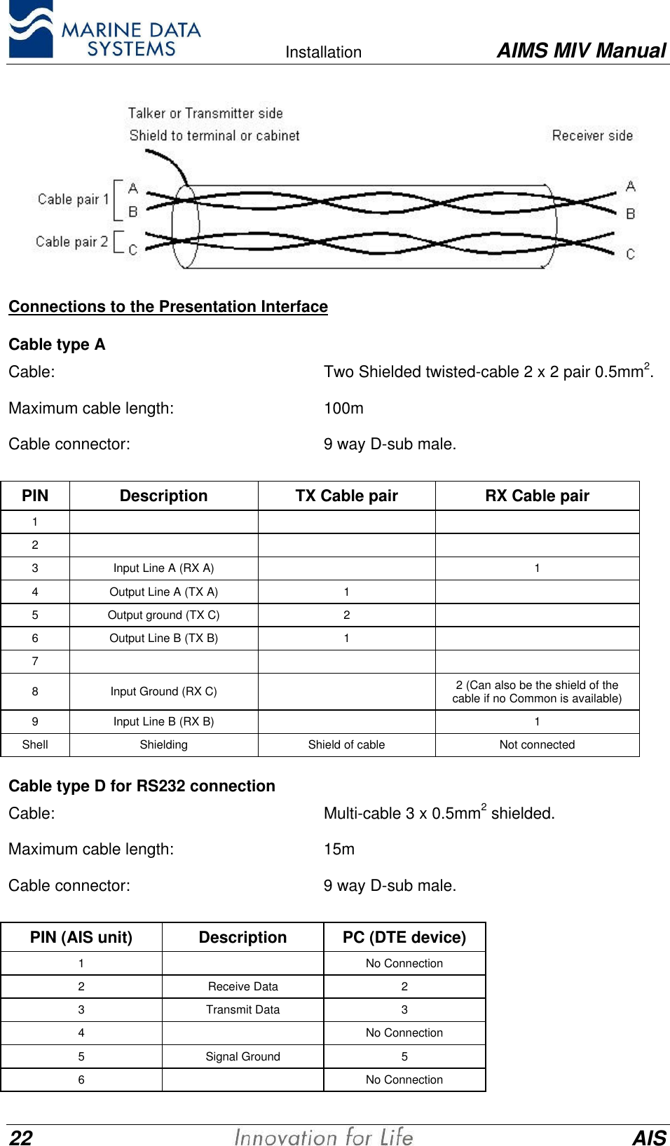
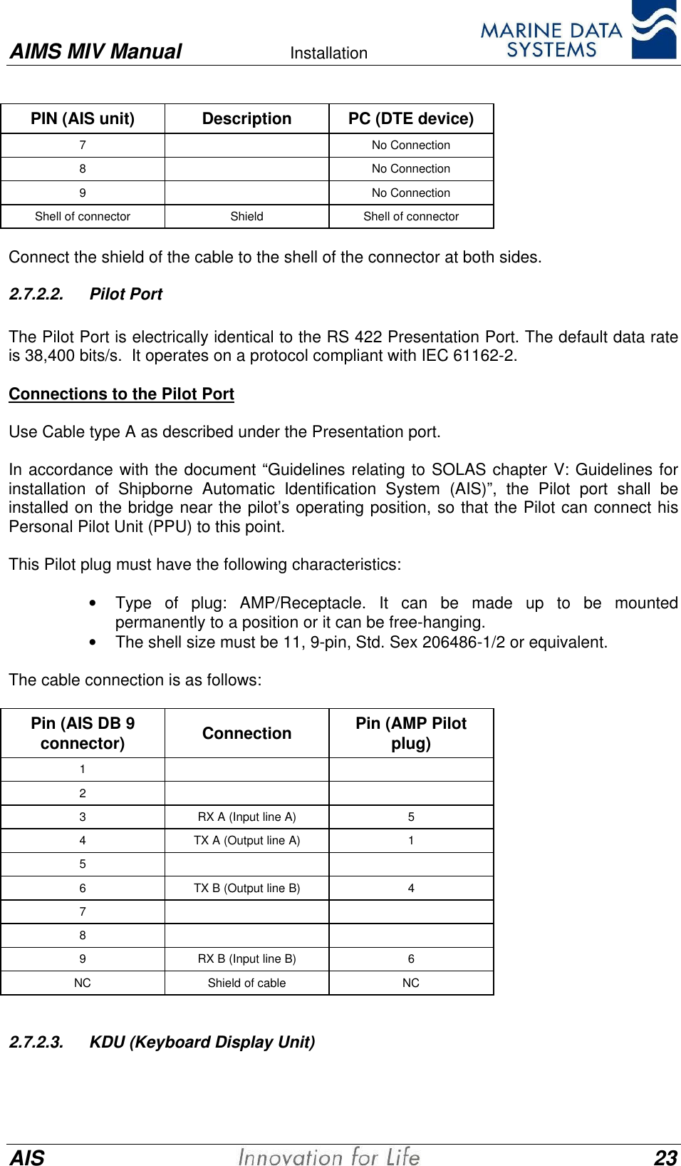
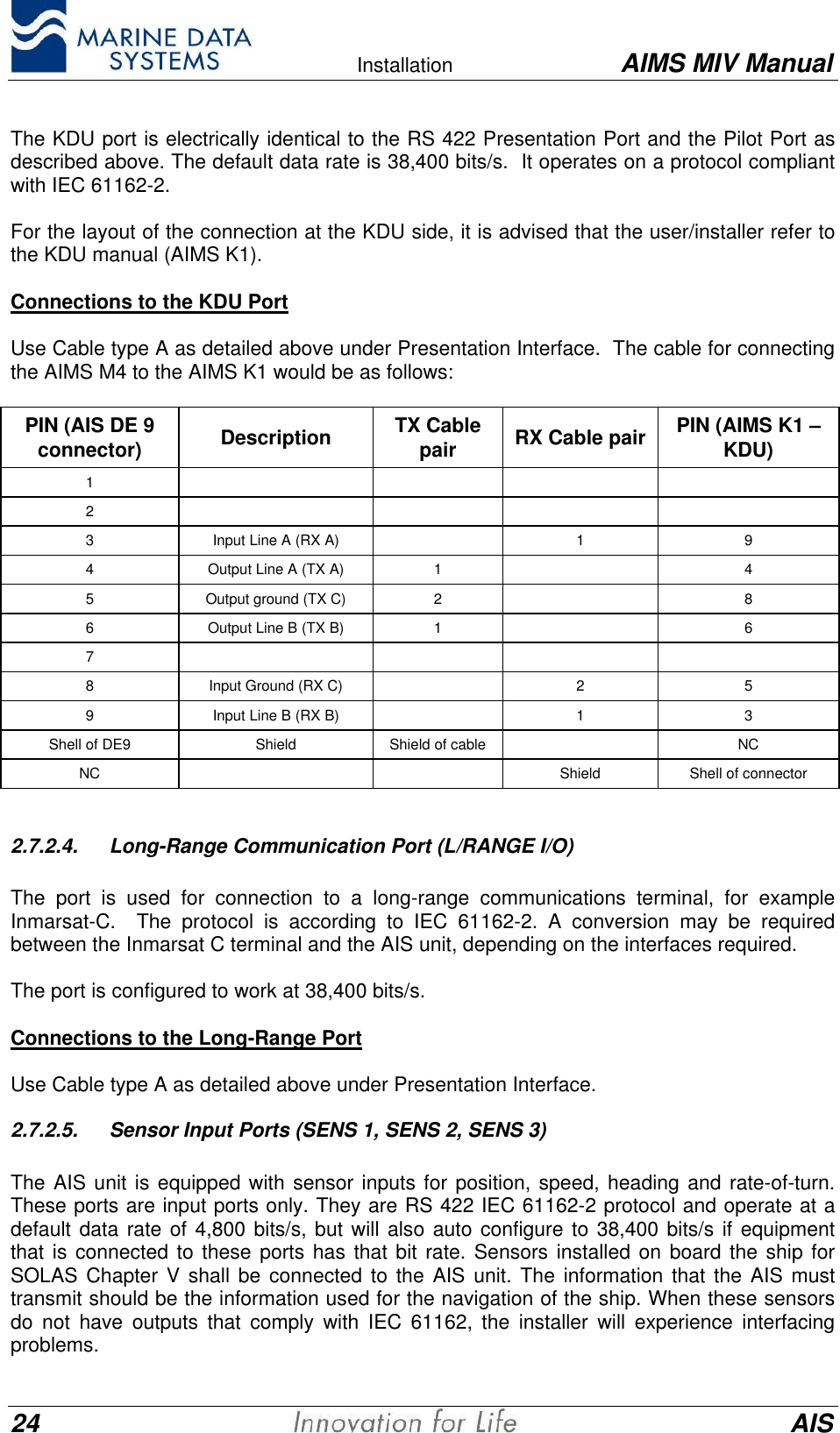
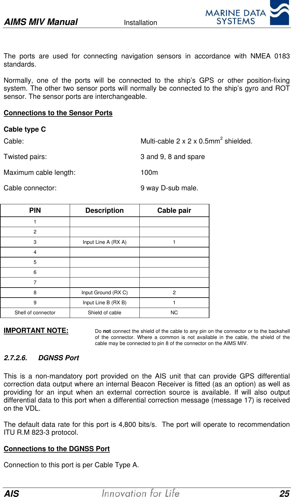
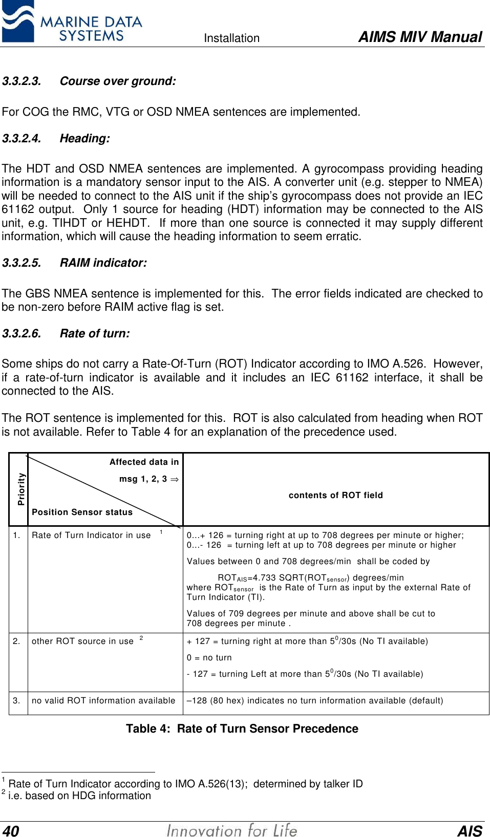
![Introduction AIMS MIV Manual10 AISAdjacent Channel Rejection 70dB (25kHz)Blocking ≥ 84dBImage Rejection ≥ 70dBIF Rejection ≥ 70dBFrequency Stability ±1ppmNOTE: When required, the AIS Unit may be equipped with a 4th receiver. This can be used where it is required toreceive additional data such as radar footprint broadcasts from a shore station without interfering withnormal AIS operation. It is also possible to replace the DSC receiver with another AIS receiver when DSCis not required. Contact your distributor for more details.1.2.9. Alarm RelayThe AIS unit has an alarm relay built-in as a standard feature. It is accessible using thealarm interface connector, located on the rear panel.Contact ratingVoltage (Average) 24VDCCurrent (Maximum) 1A1.2.10. Compass Safe DistanceCompass Safe measurements, in accordance with IEC 60945, are given below in metres:Distance from Compass(m) Compass Reading (Degrees) Compass Deviation (Reading-Background)(Degrees)Background (No EUTPresent) 270.00 -0.1 276.7 6.70.2 271.1 1.10.3 270.2 0.20.4 270.0 0.00.5 270.0 0.00.6 270.0 0.0It is recommended to mount the AIS unit more than 1m from the compass to prevent anyinterference.1.2.11. Navigation Specifications (Internal Sensors)8/12 Channel Internal Global Positioning System (GPS) [Standard].Internal Differential Beacon Receiver (DBR) [Optional].NOTE:The ship’s GPS/DGPS NMEA sensor will normally be connected to any of the three sensor input ports(Sensor 1, Sensor 2 or Sensor 3). The internal GPS is always present but is only used for acquiringposition data when it is differentially corrected and an external differentially corrected GPS is not available.Refer to Table 3: Position Sensor Precedence, on page 39, for a full position sensor precedence listing.](https://usermanual.wiki/Marine-Data-Systems/MIV30/User-Guide-306926-Page-10.png)