Micronet NB811 BLUETOOTH AND WIFI MODULE User Manual CE 500
Micronet LTD. BLUETOOTH AND WIFI MODULE CE 500
UserManual.wiki
>
Micronet
>
NB811 User Manual
Users Manual
Navigation menu
Upload a User Manual
Namespaces
Wiki Guide
HTML
PDF
Info
Views
User Manual
Discussion / Help
Navigation


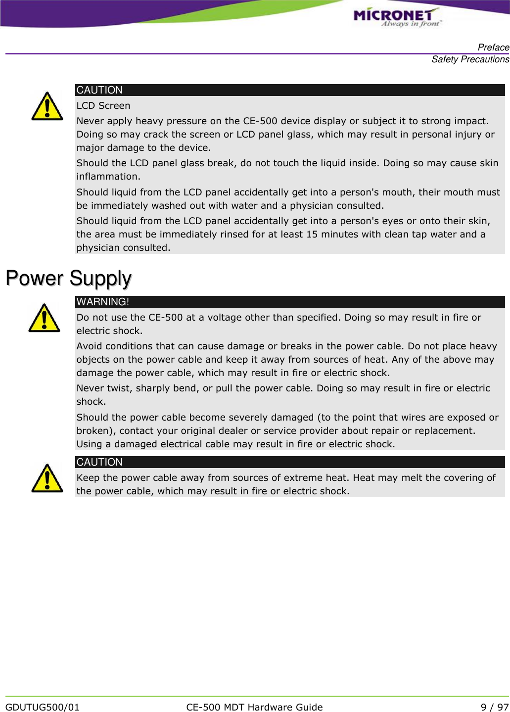
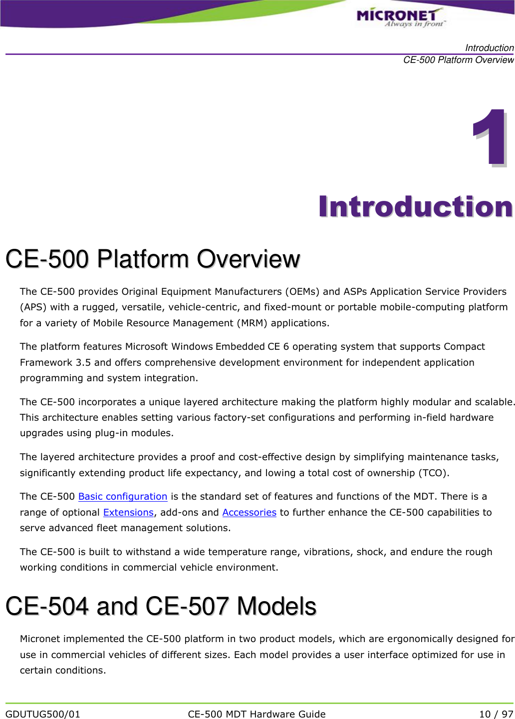
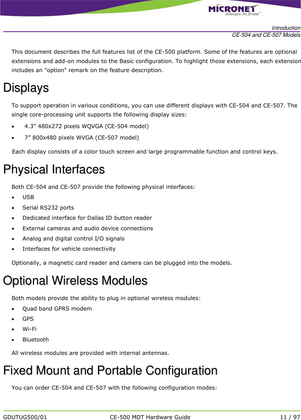
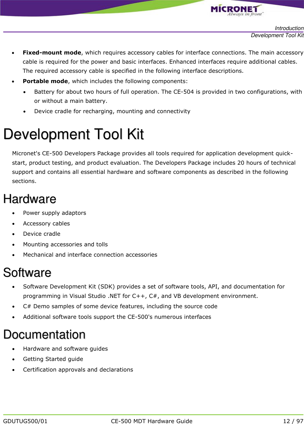


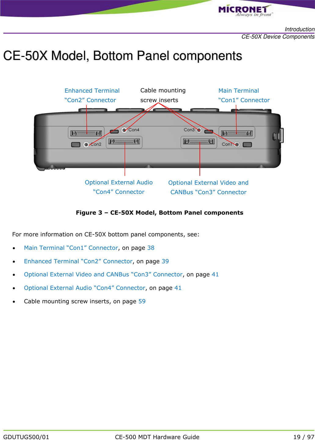


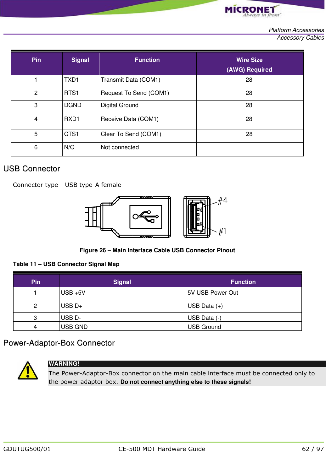
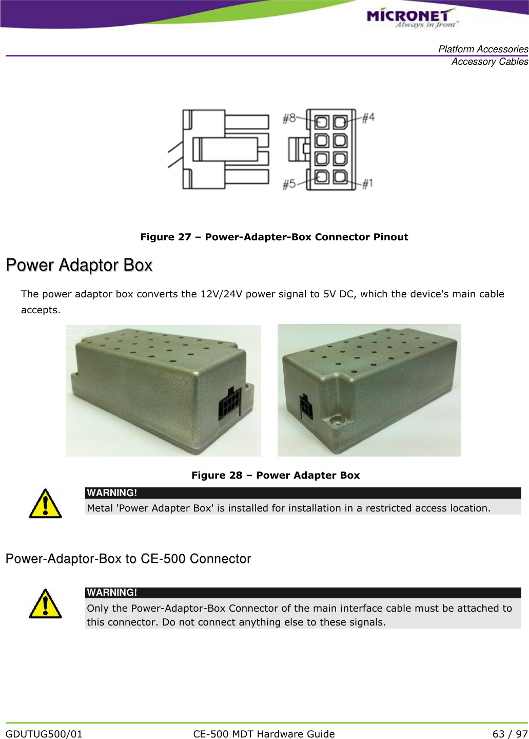
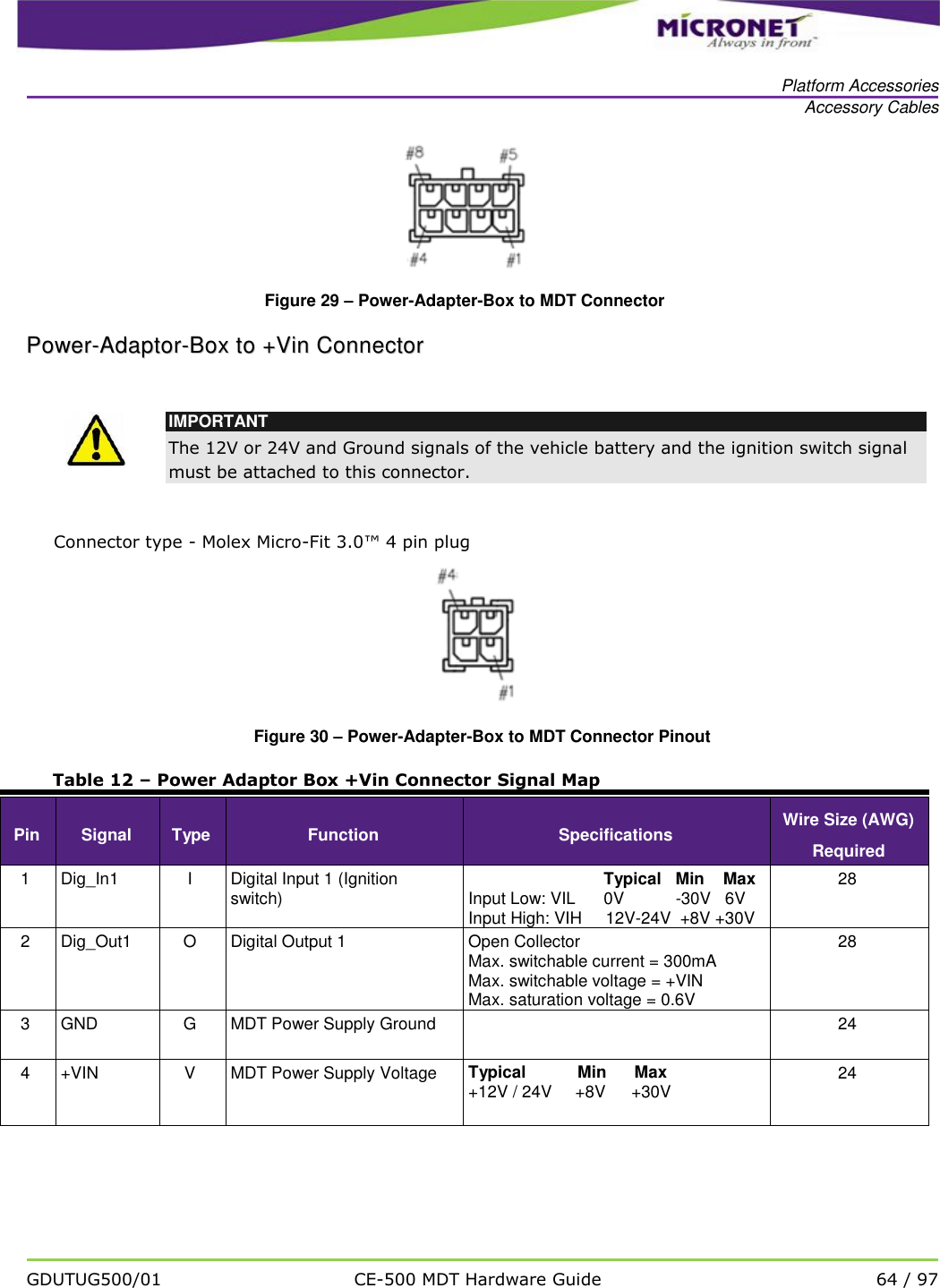
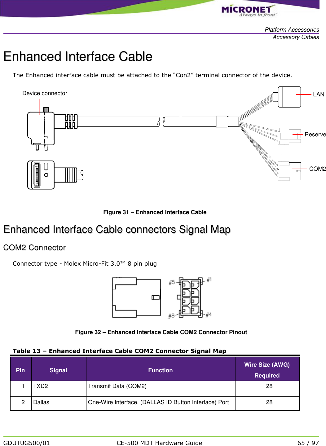
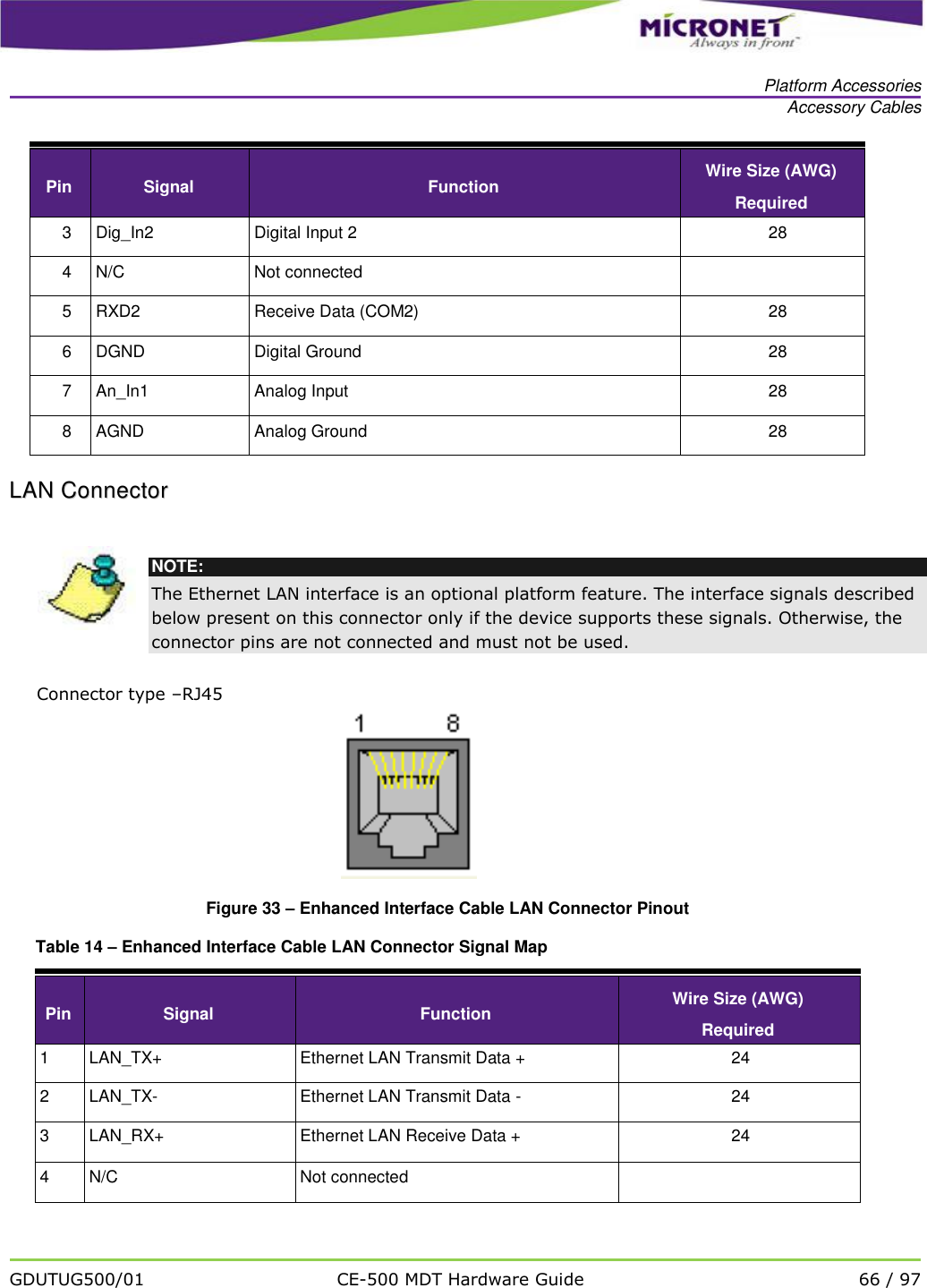
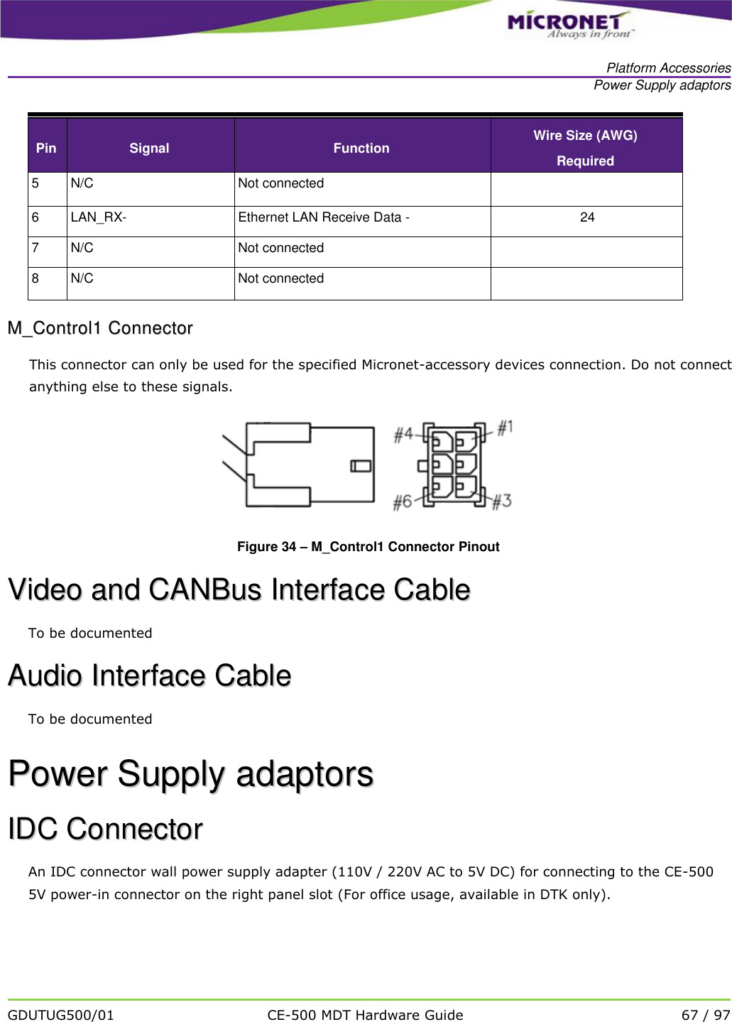
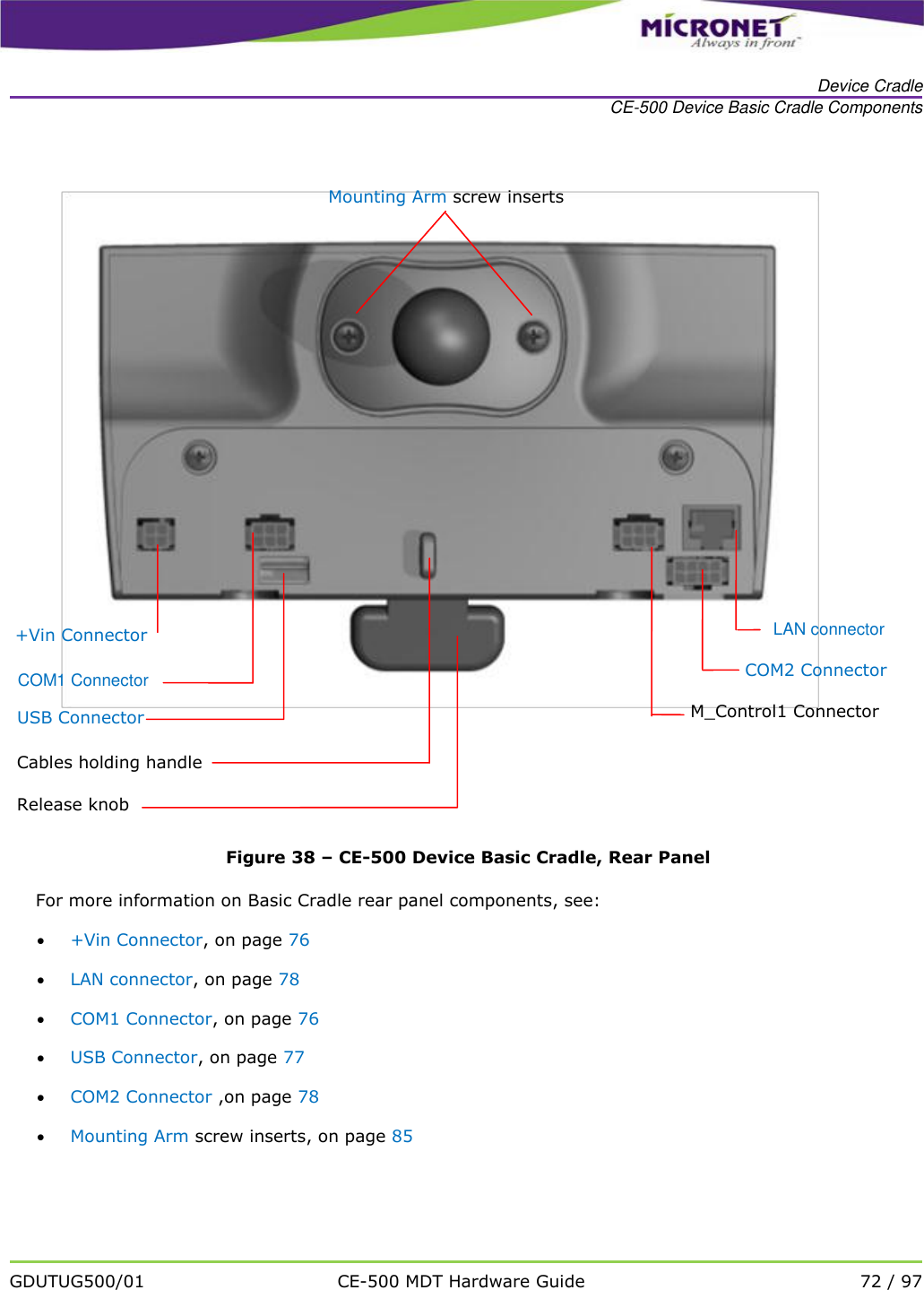
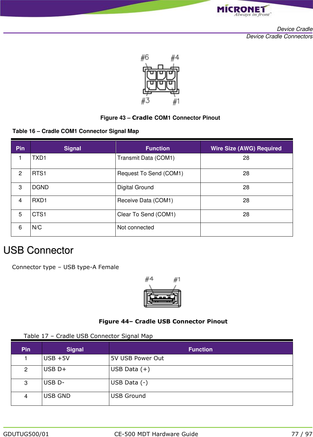
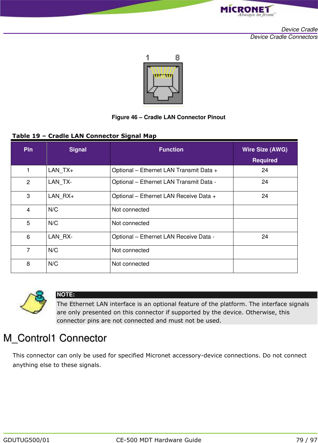
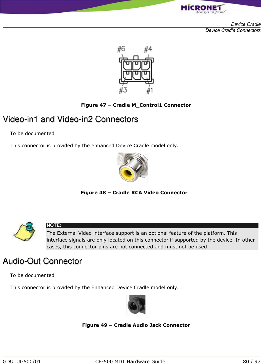
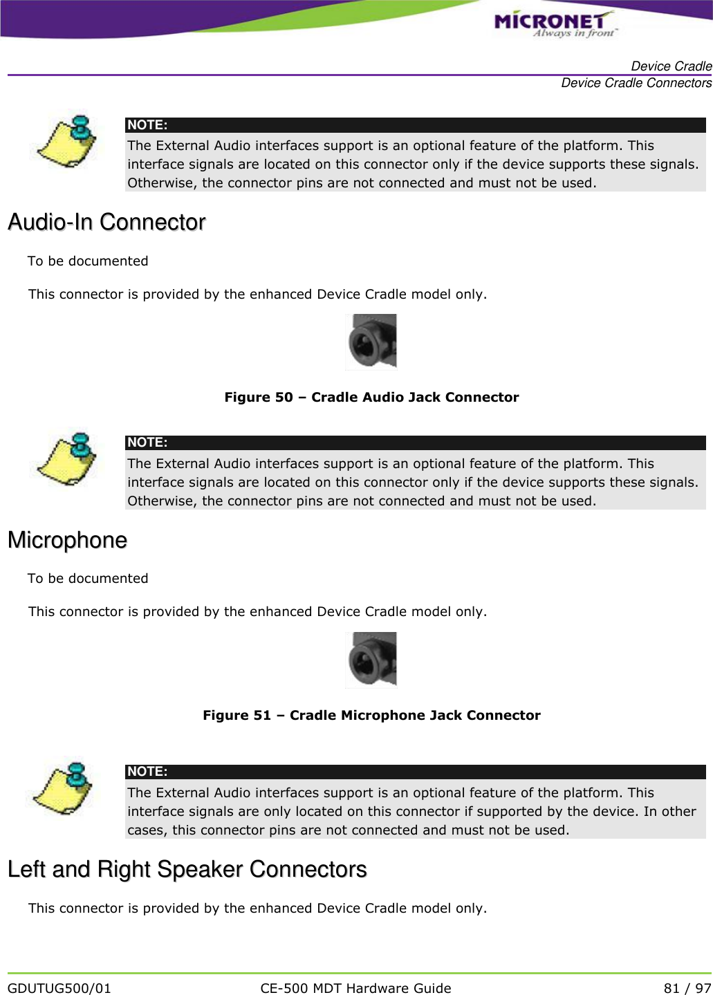
![Optional Feature Modules Wireless Communication GDUTUG500/01 CE-500 MDT Hardware Guide 56 / 97 The CE-500 system supports the following Bluetooth communication profiles: SPP [Service (Serial) Port Profile] LAP (LAN Access Profile, applicable in professional license only) PAN (Personal Area Networking) Profile GAP (Generic Access Profile) TBD GOEP (Generic Object Exchange Profile) TBD HCRP (Hardcopy Cable Replacement Profile) TBD DUN (Dial-Up Network) Profile TBD FTP (File Transfer Profile) TBD HID (Human Interface Device) Profile TBD HFP (Hands-Free Profile) TBD HSP (Headset Profile) TBD OPP (Object Push Profile) TBD WWiirreelleessss LLAANN aanndd BBlluueettooootthh CCllaassss22 MMoodduullee SSppeecciiffiiccaattiioonnss Table 9 – Wireless LAN and Bluetooth Class2 Module Specifications Functions Specifications WLAN Standard IEEE 802.11b/g, Wi-Fi compliant Bluetooth Standard Bluetooth 2.1+EDR (Enhanced Data Rate) Major Chipset Marvell 8688 Frequency Range 2.4 GHz ISM radio band Number of Channels - 802.11b: USA, Canada and Taiwan – 11 - Most European Countries – 13 - France – 4, Japan – 14 - 802.11g: USA, Canada and Taiwan – 11 - Most European Countries – 13 - Japan – 13 Modulation - DSSS, OFDM, DBPSK, DQPSK, CCK, 16- QAM, 64-QAM for WLAN - GFSK (1Mbps), Π/4 DQPSK (2Mbps) and 8DPSK (3Mbps) for Bluetooth Output Power WLAN: - 802.11b(Ch1~13): typical 15dBm +/- 2dBm - 802.11b(Ch14): typical 10dBm +/- 2dBm - 802.11g: typical 12dBm +/- 2dBm](https://usermanual.wiki/Micronet/NB811/User-Guide-1424480-Page-56.png)