Miller Edge MDTR3 CONTROL ALARM TRANSMITTER User Manual OYE MDTR3 UserMan
Miller Edge, Inc. CONTROL ALARM TRANSMITTER OYE MDTR3 UserMan
UserManual.wiki
>
Miller Edge
>
MDTR3 User Manual
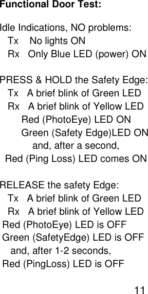
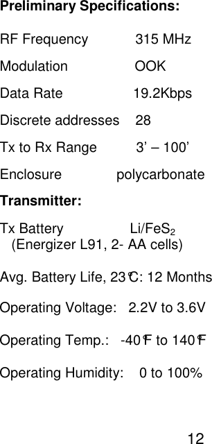
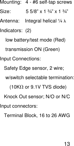
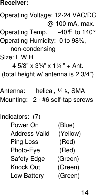
Users Manual
Navigation menu
Upload a User Manual
Namespaces
Wiki Guide
HTML
PDF
Info
Views
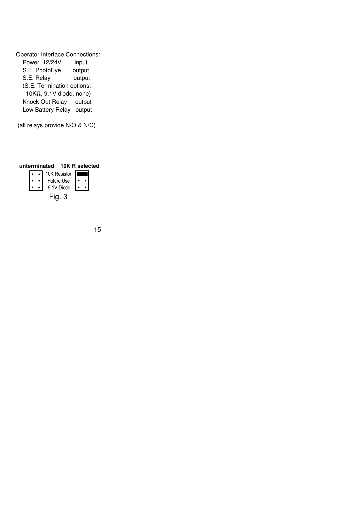
User Manual
Discussion / Help
Navigation