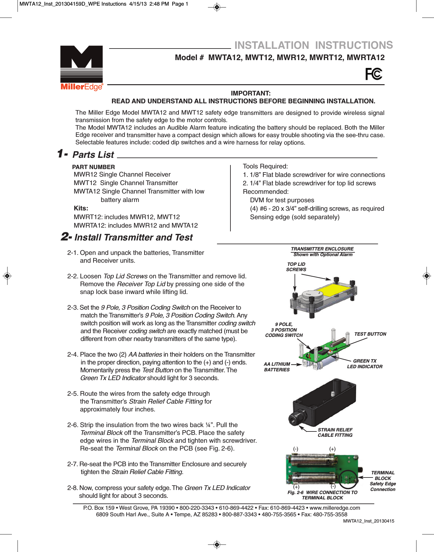
Miller Edge MWT120 318 MHz SINGLE CHANNEL TRANSMITTER User Manual WPE Instuctions

Miller Edge, Inc. 318 MHz SINGLE CHANNEL TRANSMITTER WPE Instuctions

User Manual

2-1. Open and unpack the batteries, Transmitter and Receiver units.2-2. Loosen Top Lid Screws on the Transmitter and remove lid.         Remove the Receiver Top Lid by pressing one side of the snap lock base inward while lifting lid.2-3. Set the 9 Pole, 3 Position Coding Switch on the Receiver tomatch the Transmitter’s 9 Pole, 3 Position Coding Switch. Any switch position will work as long as the Transmitter coding switchand the Receiver coding switch are exactly matched (must be  different from other nearby transmitters of the same type).2-4. Place the two (2) AA batteries in their holders on the Transmitter in the proper direction, paying attention to the (+) and (-) ends.Momentarily press the Test Button on the Transmitter. The Green Tx LED Indicator should light for 3 seconds.2-5. Route the wires from the safety edge through                 the Transmitter’s Strain Relief Cable Fitting forapproximately four inches. 2-6. Strip the insulation from the two wires back ¼”. Pull the Terminal Block off the Transmitter’s PCB. Place the safetyedge wires in the Terminal Block and tighten with screwdriver. Re-seat the Terminal Block on the PCB (see Fig. 2-6).2-7. Re-seat the PCB into the Transmitter Enclosure and securely tighten the Strain Relief Cable Fitting.2-8. Now, compress your safety edge. The Green Tx LED Indicatorshould light for about 3 seconds.P.O. Box 159 • West Grove, PA 19390 • 800-220-3343 • 610-869-4422 • Fax: 610-869-4423 • www.milleredge.com6809 South Harl Ave., Suite A • Tempe, AZ 85283 • 800-887-3343 • 480-755-3565 • Fax: 480-755-3558MWTA12_Inst_20130415Model #  MWTA12, MWT12, MWR12, MWRT12, MWRTA12INSTALLATION  INSTRUCTIONSIMPORTANT: READ AND UNDERSTAND ALL INSTRUCTIONS BEFORE BEGINNING INSTALLATION.Parts ListMWR12 Single Channel Receiver MWT12  Single Channel TransmitterMWTA12 Single Channel Transmitter with low battery alarmKits:MWRT12: includes MWR12, MWT12MWRTA12: includes MWR12 and MWTA121-PART NUMBER2- Install Transmitter and TestThe Miller Edge Model MWTA12 and MWT12 safety edge transmitters are designed to provide wireless signaltransmission from the safety edge to the motor controls.The Model MWTA12 includes an Audible Alarm feature indicating the battery should be replaced. Both the MillerEdge receiver and transmitter have a compact design which allows for easy trouble shooting via the see-thru case.Selectable features include: coded dip switches and a wire harness for relay options.Tools Required:1. 1/8” Flat blade screwdriver for wire connections2. 1/4” Flat blade screwdriver for top lid screwsRecommended:DVM for test purposes(4) #6 - 20 x 3/4” self-drilling screws, as required Sensing edge (sold separately)TOP LIDSCREWS AA LITHIUMBATTERIESFig. 2-6  WIRE CONNECTION TO TERMINAL BLOCKSTRAIN RELIEFCABLE FITTINGTERMINALBLOCKSafety EdgeConnection9 POLE, 3 POSITIONCODING SWITCHTRANSMITTER ENCLOSUREShown with Optional AlarmTEST BUTTONGREEN TXLED INDICATOR(-)(-)(+)(+)MWTA12_Inst_201304159D_WPE Instuctions  4/15/13  2:48 PM  Page 1
P.O. Box 159 • West Grove, PA 19390 • 800-220-3343 • 610-869-4422 • Fax: 610-869-4423 • www.milleredge.com6809 South Harl Ave., Suite A • Tempe, AZ 85283 • 800-887-3343 • 480-755-3565 • Fax: 480-755-35583- Install Receiver and Test3-1. Mount Receiver inside the operator control box so that the wires from the receiver will reach the terminal strip on the operator.3-2. Wiring:a. The red (+) and black (-) wires are your power leads. They connect to your operator panel terminals that provide the appropriate power (12-24 VAC/VDC). Black wire is common,Red wire is (+) or AC power.b. The green wire is your standard antenna wire. This must be located outside of any metal enclosure to provide for good signal reception. There is an F-Connector antenna fitting included on the receiver in the event a remote antenna placement is needed.c. Receiver Connections: The white wire will go to your operator’s low voltage common terminal. If your operator requires a normally open (N.O.) contact, connect the yellow wire to the operator’s safety edge input. If the operator requires a normally closed (N.C.) contact, connect the orange wire to the operator’s safety edge input.3-3. Preliminary Test:Confirm that once power is applied to the Receiver, it’s green LED is lit. Now press the Transmitter's test button and notice that the red LED lights up on the Receiver and the green LED lights up on the Transmitter. 3-4. Replace the Receiver Top Lid. 4- Safety Test4-1.  While closing the door or gate, momentarily activate the safety edge and confirm that the motor stops and reverses the door or gate direction.CH 1ANTENNARECEIVER ENCLOSURE(4) PRE-DRILLEDCORNERMOUNTING HOLESLEDINDICATORSMOUNTING SCREW HOLES2- Install Transmitter and Test Cont.2-9.   The four (4) Pre-Drilled Corner Mounting Holesare located on the far corners of the Transmitter Enclosure. Mount the Transmitter to the gate post, door end stile, or bottom angle using (4)#6 - 20 x 3/4” self-drilling screws. Mount the transmitter with the wire outlet facing down or to the side.2-10. Replace the cover on the Transmitter and tighten the Top Lid Screws, taking care to align the lid.MWTA12_Inst_201304159 POLE, 3 POSITIONCODING SWITCHF-CONNECTORANTENNA FITTINGMWTA12_Inst_201304159D_WPE Instuctions  4/15/13  2:48 PM  Page 2
P.O. Box 159 • West Grove, PA 19390 • 800-220-3343 • 610-869-4422 • Fax: 610-869-4423 • www.milleredge.com6809 South Harl Ave., Suite A • Tempe, AZ 85283 • 800-887-3343 • 480-755-3565 • Fax: 480-755-35585- Specifications and Controls: Transmitter UnitCode Switch: Selectable 9 pole, 3 position DIPFrequency: 318 MHz.Indicator Lights- Tx: Green LED: Tx DataMounting: (4) #6 self drilling screws includedPower Source: Batteries: 2 AA, 1.5v Alkaline or Lithium**Recommended for extended life in prolonged cold environments. Life expectancy: 2 yrs.Enclosure Rating: NEMA4Modulation: On-Off KeyingCable Connections: Screw clamp type terminal blocks for 14-26 awg wire.Dimensions:  MWT12: 5.62”w x  1.75”h x 1.75”dMWTA12: 5.62”w x  2.125”h x 1.75”dAntenna: Integral helical antenna.Test Button: Momentary push button – Forces the transmission of the transmitter's address.Low Battery: Model #MWTA12 only 80-95dB Audible Alarm: Tx Alkaline battery fails below  0o :  Lithium -40oTransmitted Signal Duration: Approx. 3 secondsResponse Time: Nominal 70 msec; end to end6-Specifications and Controls: Receiver UnitCode Switch: Selectable 9 pole, 3 position DIPIndicator Lights - Rx: Green LED: Power on; Red LED: Relay energized, indicates safety edge activationPower Source: 10 to 40 VDC, 10-30 VAC (RMS)Power Consumption: 15 mA (avg.) with Relay Off; 54 mA (avg.) with Relay On (1 Channel); (Max 128mA, 3 Ch.)Dimensions: 4.75”w x  3.75”h x 1.25”dCable Connections: Integral 18” wiring with #6 spade lugs.Maximum Operating Distance: 100 FeetTransmitter:FCC ID: OYE-MWT120THIS DEVICE COMPLIES WITH PART 15 OF THE FCC RULES. OPERATIONS IS SUBJECT TO THE FOLLOWINGTWO CONDITIONS.1) THIS DEVICE MAY NOT CAUSE HARMFUL INTERFERENCEAND2) THIS DEVICE MUST ACCEPT ANY INTERFERENCE RECEIVED INCLUDING INTERFERENCE THAT MAYCAUSE UNDESIRED OPERATION.7- FCC ComplianceThis equipment has been tested and found to comply with the limits for a Class B digital device, pursuant to Part15 of the FCC Rules.These limits are designed to provide reasonable protection against harmful interference in a residential installation. This equipmentgenerates, uses and can radiate radio frequency energy and, if not installed and used in accordance with the instructions, may causeharmful interference to radio communications. However, there is no guarantee that interference will not occur in a particular installa-tion. If this equipment does cause harmful interference to radio or television reception, which may be determined by turning the equip-ment off and on, the user is encouraged to try to correct the interference by one or more of the following measures:1- Re-orient or relocate the receiver antenna2- Increase the separation between the equipment and the receiver3- Connect the equipment into an outlet on a circuit different from that to which the receiver is connected.4- Consult the dealer or an experienced radio/TVtechnician for help.Changes or Modifications Not Expressly Approved By The Party Responsible For Compliance Could Void The User’sAuthority To Operate The Equipment.MWTA12_Inst_20130415MWTA12_Inst_201304159D_WPE Instuctions  4/15/13  2:48 PM  Page 3

Navigation menu