Mipro Electronics Co MT-90 Wireless Mixer User Manual MA909 2CE194
Mipro Electronics Co Ltd Wireless Mixer MA909 2CE194
UserManual.wiki
>
Mipro Electronics Co
>
MT-90 User Manual
>
Users Manual Part 3
Contents
1.
Users Manual Part 1
2.
Users Manual Part 2
3.
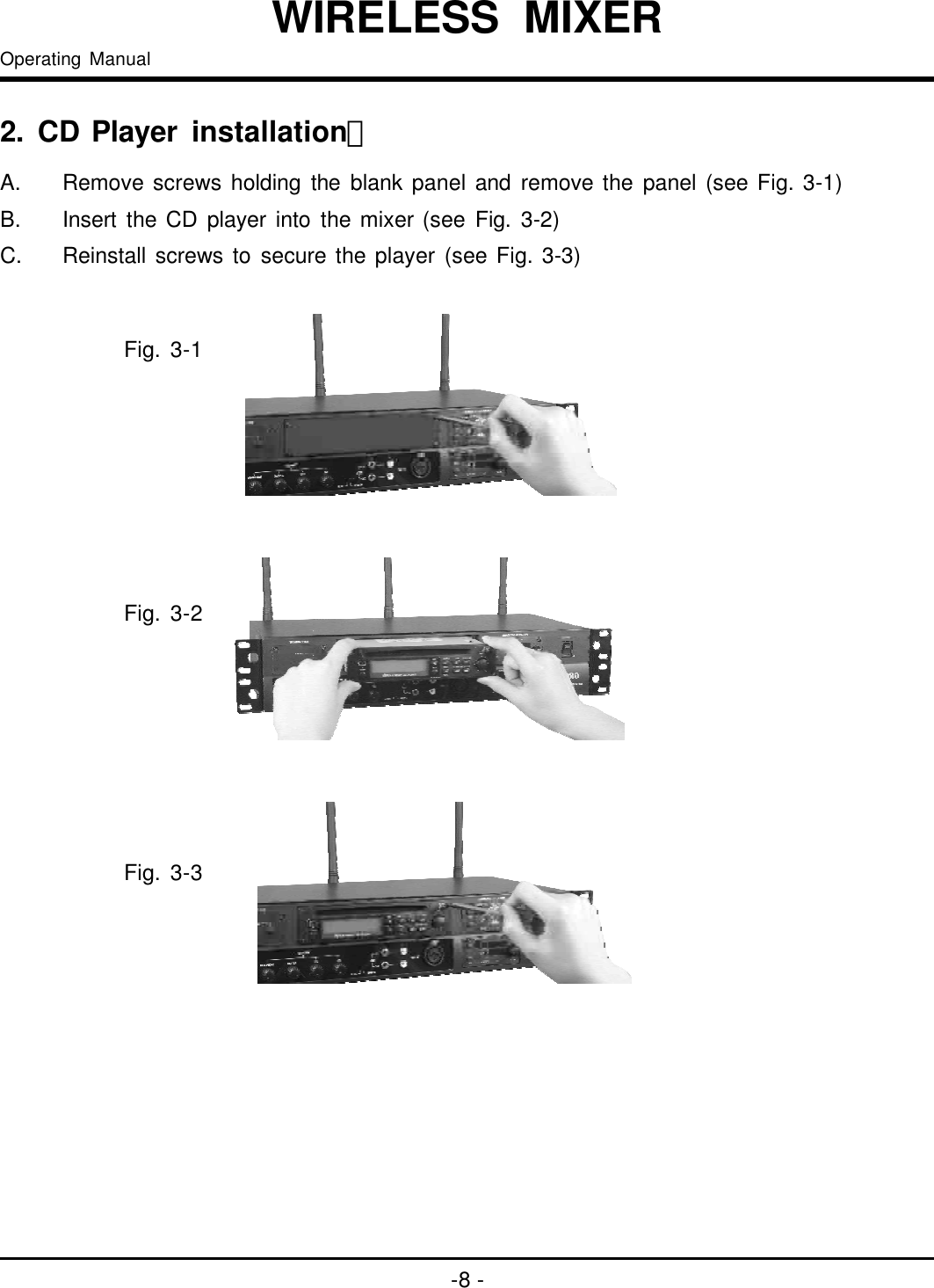
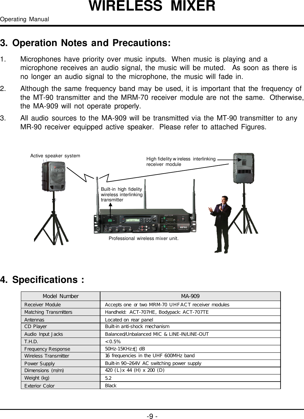
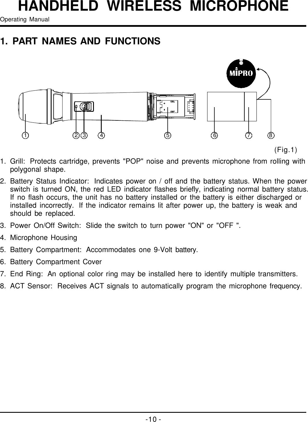
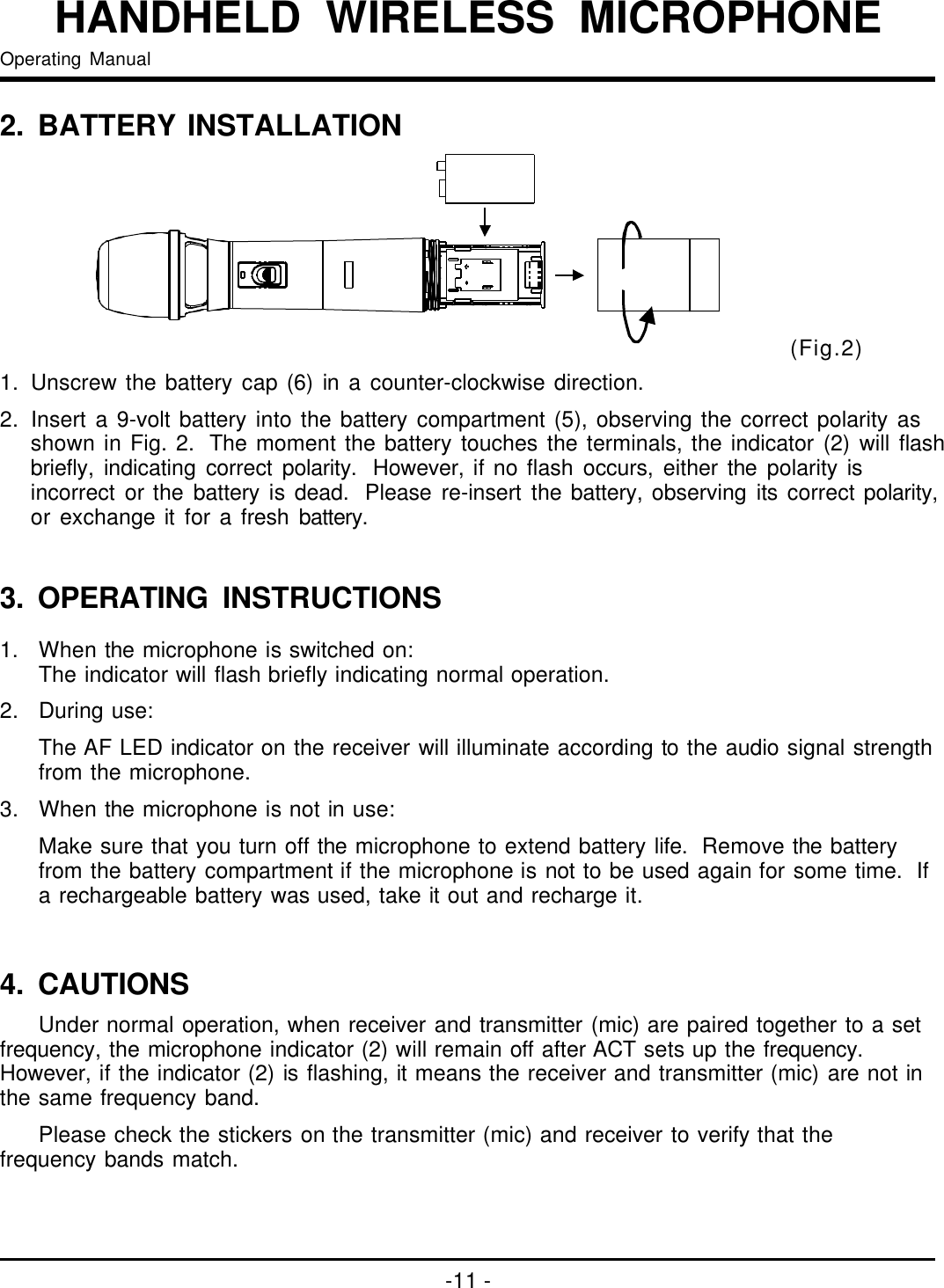
Users Manual Part 3
Users Manual Part 3
Navigation menu
Upload a User Manual
Namespaces
Wiki Guide
HTML
PDF
Info
Views
User Manual
Discussion / Help
Navigation