Mobiletron Electronics TPV03 Tai-Safety-H Tire Pressure Monitoring System User Manual Safety Plus User s Manual

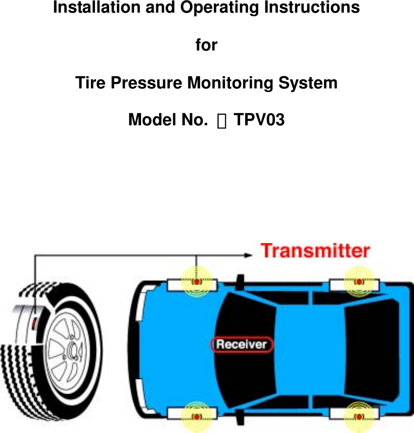
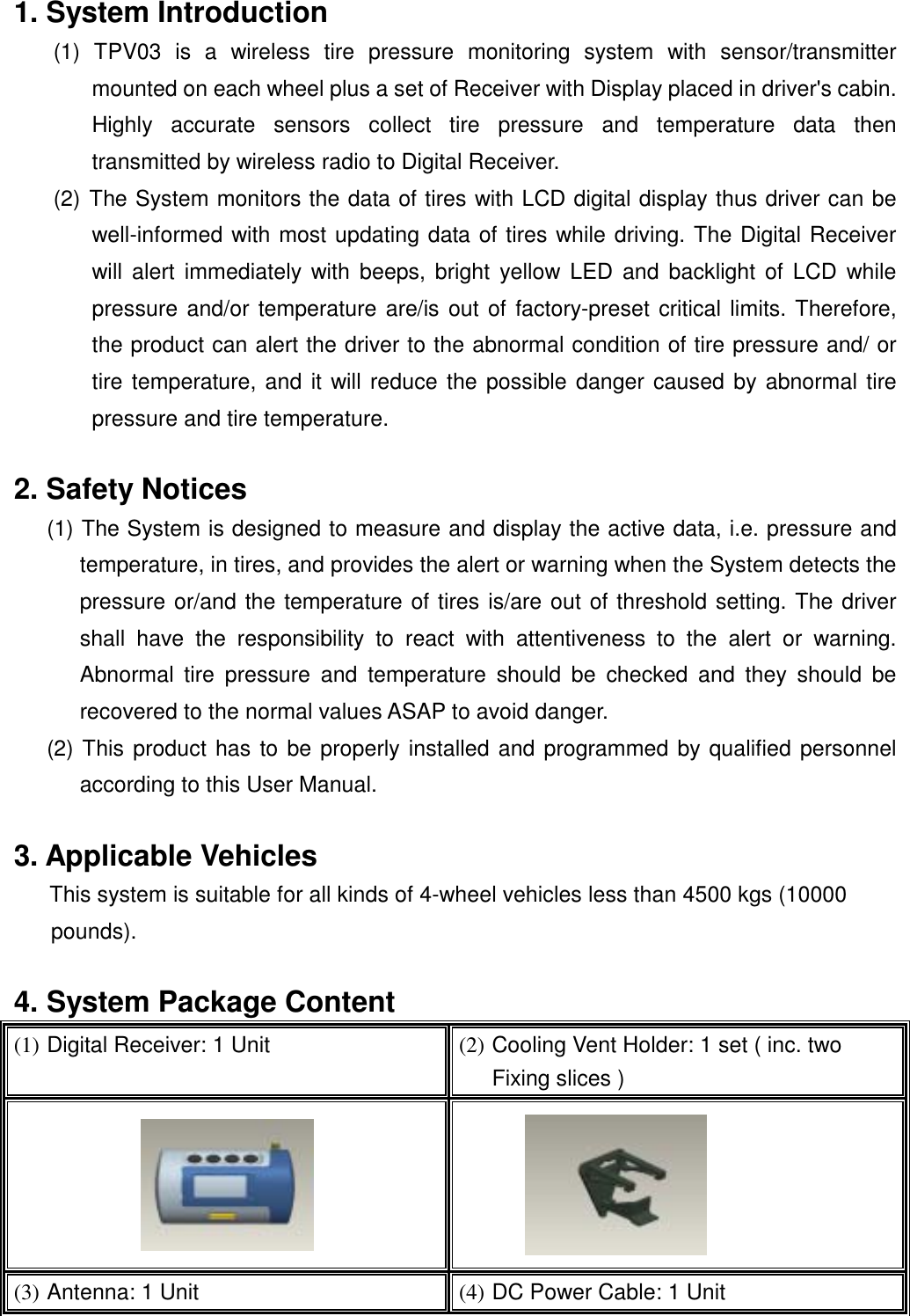
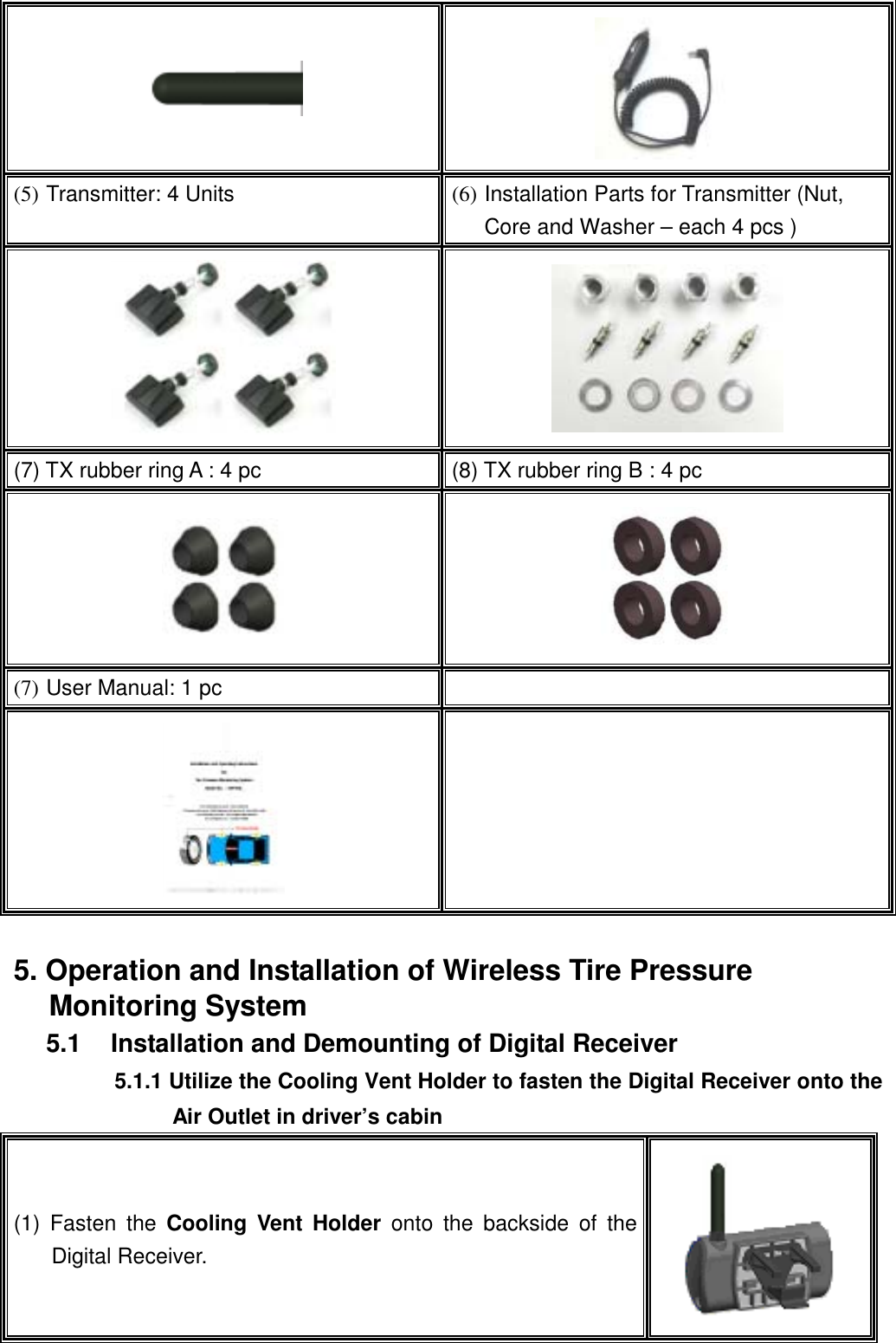
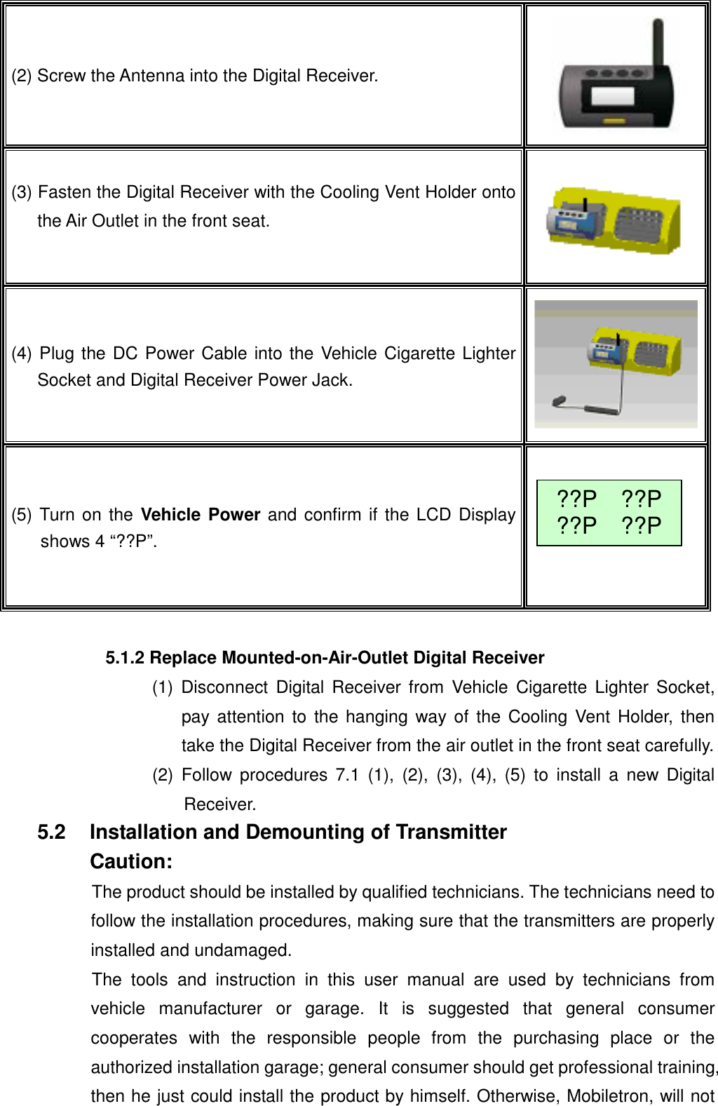
Mobiletron Electronics Co., Ltd. Tai-Safety-H Tire Pressure Monitoring System Safety Plus User s Manual

Users Manual

      Installation and Operating Instructions for Tire Pressure Monitoring System Model No.  :TPV03
 Contents 1.  System Introduction   2. Safety Notices   3. Applicable Vehicles   4.  System Package Content   5.  Operation and Installation of Wireless Tire Pressure Monitoring System   5.1 Installation and Mounting of Digital Receiver         5.1.1 Utilize the Cooling Vent Holder to fasten the Digital Receiver           5.1.2 Replace Mounted-on-Air-Outlet Digital Receiver     5.2 Installation and Demounting of Transmitter         5.2.1 Mounting the Tire with Transmitter on Wheel Rim         5.2.2 De-Mounting Tire with Transmitter Inside   6.  Digital Receiver Function Description     6.1 Digital Receiver Diagram, Display Control and Indicators     6.2 Digital Receiver Button Function Description   7.  Alarms and Warnings     7.1 Pressure Threshold Alarm and Warning     7.2 Temperature Threshold Alarm and Warning     7.3 No Data Received   8.  General Set Up Mode     8.1 Manual Pressure Threshold Setting         8.1.1 Manual Low Pressure Threshold Setting         8.1.2 Manual High Pressure Threshold Setting     8.2 Manual Temperature Threshold Setting    8.3 Reset     8.4 Restore Factory-Preset Value     8.5 Recall Last Measured Tire Pressure and Temperature Values     8.6 Transmitter ID Input Via Auto Learning Feature -- “Search Tx”     8.7 Exit General Set Up Mode   9.  Special Set Up Mode     9.1 Tire Exchange Mode     9.2 Transmitter ID Change Mode     9.3 Set Pressure Unit Mode     9.4 Set Temperature Unit Mode     9.5 Display Wheel Location Mode     9.6 Exit Special Set Up Mode   10. Limit Warranty     10.1 Warranty Service     10.2 This Limited Warranty Provided by Mobiletron Does Not Cover   11. Things to Notice   12. Component List   13. Technical Specifications                      13.1 Transmitter                      13.2 Digital Receiver   14. Tire Rotation Table
 1. System Introduction   (1) TPV03 is a wireless tire pressure monitoring system with sensor/transmitter mounted on each wheel plus a set of Receiver with Display placed in driver's cabin. Highly accurate sensors collect tire pressure and temperature data then transmitted by wireless radio to Digital Receiver. (2) The System monitors the data of tires with LCD digital display thus driver can be well-informed with most updating data of tires while driving. The Digital Receiver will alert immediately with beeps, bright yellow LED and backlight of LCD while pressure and/or temperature are/is out of factory-preset critical limits. Therefore, the product can alert the driver to the abnormal condition of tire pressure and/ or tire temperature, and it will reduce the possible danger caused by abnormal tire pressure and tire temperature.  2. Safety Notices (1) The System is designed to measure and display the active data, i.e. pressure and temperature, in tires, and provides the alert or warning when the System detects the pressure or/and the temperature of tires is/are out of threshold setting. The driver shall have the responsibility to react with attentiveness to the alert or warning. Abnormal tire pressure and temperature should be checked and they should be recovered to the normal values ASAP to avoid danger. (2) This product has to be properly installed and programmed by qualified personnel according to this User Manual.  3. Applicable Vehicles This system is suitable for all kinds of 4-wheel vehicles less than 4500 kgs (10000 pounds).   4. System Package Content (1) Digital Receiver: 1 Unit  (2) Cooling Vent Holder: 1 set ( inc. two Fixing slices )   (3) Antenna: 1 Unit  (4) DC Power Cable: 1 Unit
   (5) Transmitter: 4 Units  (6) Installation Parts for Transmitter (Nut, Core and Washer – each 4 pcs )       (7) TX rubber ring A : 4 pc  (8) TX rubber ring B : 4 pc   (7) User Manual: 1 pc      5. Operation and Installation of Wireless Tire Pressure Monitoring System 5.1  Installation and Demounting of Digital Receiver 5.1.1 Utilize the Cooling Vent Holder to fasten the Digital Receiver onto the Air Outlet in driver’s cabin (1) Fasten the Cooling Vent Holder onto the backside of the Digital Receiver.
 (2) Screw the Antenna into the Digital Receiver.  (3) Fasten the Digital Receiver with the Cooling Vent Holder onto the Air Outlet in the front seat.  (4) Plug the DC Power Cable into the Vehicle Cigarette Lighter Socket and Digital Receiver Power Jack. (5) Turn on the Vehicle Power and confirm if the LCD Displayshows 4 “??P”.  ??P  ??P??P  ??P 5.1.2 Replace Mounted-on-Air-Outlet Digital Receiver (1) Disconnect Digital Receiver from Vehicle Cigarette Lighter Socket, pay attention to the hanging way of the Cooling Vent Holder, then take the Digital Receiver from the air outlet in the front seat carefully. (2) Follow procedures 7.1 (1), (2), (3), (4), (5) to install a new Digital Receiver. 5.2  Installation and Demounting of Transmitter Caution: The product should be installed by qualified technicians. The technicians need to follow the installation procedures, making sure that the transmitters are properly installed and undamaged. The tools and instruction in this user manual are used by technicians from vehicle manufacturer or garage. It is suggested that general consumer cooperates with the responsible people from the purchasing place or the authorized installation garage; general consumer should get professional training, then he just could install the product by himself. Otherwise, Mobiletron, will not
 offer any warranty if he installs the product by himself.   Tools Required:   Tire Changing Equipment   Tire Balancing Equipment   Torque Wrench  5.2.1 Mounting the Tire with Transmitter on Wheel Rim Notes:  Pair Valve Tag that has the same color as the color of text on ID Number Label of Transmitter for the identical tire as indicated in below brackets.  (1) Prepare the Transmitter to pass through the valve hole which is positioned on the steel, aluminum or aluminum alloy wheel rim.    (2) Pass the Transmitter through the valve hole and the rubber circle will push up the inside of the valve.    (3) Attach the Rubber Ring B that is the spare part of Transmitter from the outside of the wheel rim onto the valve hole.
 (4) Attach the Washer that is the spare part of Transmitter from the outside of the wheel rim onto the valve hole.      (5) Attach the Core that is the spare part of Transmitter from the outside of the wheel rim onto the valve hole.   ( => Recommendatory Torque to attach the Core: 2~3.2 Kgf.cm )    (6) Attach the Nut that is the spare part of the Transmitter from the outside of the wheel rim onto the valve hole.   ( => Recommendatory Torque to attach the Nut: 35~45 Kgf.cm )     (6) Install the tire with the standard installation equipment, and installation procedures could be proceeded by the technicians from the purchasing place or the authorized installation ort.
 (7) Install the external antenna into the transmitter valve as the   following pictures.      (8) Finalize the installation of the Transmitter.     5.2.2 De-Mounting Tire with Transmitter Inside   Please demount the product with standard demounting equipment, and demounting procedures could be proceeded by the technicians from our appointed vehicle manufacturer or garage. In addition, we would like to suggest general consumer should cooperate with the seller or the responsible people from authorized garage, if he wants to demount the product by himself, and it is a must that he has gotten the professional training in advance. If general consumer without authorization and damage the product, we will not warrant any replacement or limit warranty.  6. Digital Receiver Function Description 6.1  Digital Receiver Diagram, Display Control and Indicators      Setup Pressure  LCD Backlight LCD Display Temperature           LED Alarm Indicator
 6.2  Digital Receiver Button Function Description (1) Temperature Button  Display temperature of tires after press button  .   (2) ↓(Downward Button)  In “General Set Up Mode”, acts as downward button to select function and number.  (3) Counter-clockwise Button In  “Special Set Up Mode”, acts as counterclockwise button to select tire for programming. (1) Pressure Button  Display pressure of tires after pressing button  .  (2)↑(Upward Button)    In “General Set Up Mode”, acts as upward button to select function and number.  (3) Clockwise Button  In “Special Set Up Mode”, acts as clockwise button to select tire for programming. (1) LCD Display Backlight Button  Press button    to turn on backlight of LCD Display.  (2) Confirmation Button  In set up mode, button    acts as confirmation button.   3). Puncture Warning  When the drop rate of tire pressure higher than 0.3PSI / sec(or 2PSI / min), the transmitter will immediately warn the users, and the receiver’s LCD will show the glitter and the tire pressure”!!!”    (1) Set Up Button  Press button    to enter into “General Setup Mode”.  (2) Exit Set Up Mode  Press button    again to exit “Setup Mode”. 35C  35C36C 36C31P  31P30P  30P31P  31P30P 30P31P    !!!30P 30PPressureWarning Note:Value shown above is for reference only.
 7. Alarms and Warnings 7.1 Pressure Threshold Alarm and Warning Should Programming Manual   Threshold Setting Limit are 25psi   and 75℃ respectively while ctory-preset value are 23psi and 85℃:  fa9.1.1 Tire pressure lower than Manual Pressure Threshold Setting: A Low Pressure Warning is initiated when the pressure drops below the programmed Pressure Threshold Setting Limit。 1.  Warning Actions Include: 1st.  LED Alarming Indicator blinks once。 2nd.  An short audio alarm。 2.  Suggested Action to Warning: 1 st.  When the warning occurs, reduce speed and proceed to a safe location to check tires。  1.LCD Display will remain normal when measured pressure is 24psi.  Tire pressure drops below Factory-Preset Pressure Threshold Setting: A Low Pressure Alarm is initiated when the pressure drops below Factory-Preset Threshold Setting Limit,i.e. 23psi。 Alarm Actions Include: 1.  Affected tire/s with its corresponding Pressure digit/s kept on flashing。 2.  An long audio alarm。 3.  LCD Display Backlight remains on;LED Alarming Indicator remains on。Cancel Alarm Temporarily: 1.  Proceed  “Reset” as depicted on “General Set Up Mode” Section c。Suggested Action to Alarm: 1.  When the alarm occurs,reduce speed and proceed to a safe location to check tires。 Note :The Pressure Deviation Alarm will disappear when the tires are properly re-inflated to correct levels。    a. b. c. d. e. 30P  32P 32P  24P 31P  !20P 30P  30P Note: Value shown above is for reference only.
 7.2  Temperature Threshold Alarm and Warning Should Programming Manual Threshold Setting Limit are 25psi and 75℃respectively while factory-preset value are 23psi and 85℃: 7.2.1 Tire Temperature higher than Manual Temperature Threshold Setting: A High Temperature Warning is initiated when tire Temperature rises above the programmed Temperature Threshold Setting Limit。 1.  Warning Actions Include: 1st.  LED Alarming Indicator blinks once。 2nd.  An short audio alarm。 2.  Suggested Action to warming: When the warming occurs ,reduce speed and proceed to a safe location to check tires。 1.LCD Display will remain normal when measured temperature is between 76℃ to 84℃。    7.2.2 Tire Temperature higher than Factory-Preset Temperature Threshold Setting: A High Temperature Alarm is initiated when tire Temperature rises above the Factory-Preset Temperature Threshold Setting Limit,i.e. 85 ℃。 1.  Alarm Actions Include:   1st.  Affected tire/s with its corresponding Temperature digit/s kept on flashing。 2nd.  An long audio alarm。 3rd.  LCD Display Backlight remains on;LED Alarming Indicator remains on。 2.  Cancel Alarm Temporarily: 1st.  Proceed  “Reset” as depicted on “General Set Up Mode” Section c。 3.  Suggested Action to Alarm: When the alarm occurs,reduce speed and proceed to a safe location to check tires。      82C  50C 45C  46C !86C  66C 50C  55C Note:Value shown above is for reference only.  8. General Set Up Mode 8.1 Manual Pressure Threshold Setting 8.1.1 Manual Low Pressure Threshold Setting
 1.  Press   button for more than 2 second to go into “General Set Up Mode”。 2.  Use   button (act as downward button) and   button (act as upward button) to select “Pressure Warning “ setting。 3.  LCD Display will show:  4.  Use   button (act as downward button) and   (act as upward button) to select a number as Pressure Threshold。   5.  Press   button to conform setup value。 6.  Press  button again to exit “General Set Up Mode”。 Low Pressure Warning 26 PSI         8.1.2 Manual High Pressure Threshold Setting 1.  Press   button for more than 2 second to go into “General Set Up Mode”。 2.  Use   button (act as downward button) and   button (act as upward button) to select “Pressure Warning “ setting。 3.  LCD Display will show:  4.  Use   button (act as downward button) and   (act as upward button) to select a number as Pressure Threshold。   5.  Press   button to conform setup value。 6.  Press  button again to exit “General Set Up Mode”。 High Pressure Warning 26 PSI  8.2  Manual Temperature Threshold Setting 1. Press   button for more than 2 second to go into “General Set Up Mode”。 2. Use button (act as downward button) and    button (act as upward button) to select “Temp. Warning” setting。 3.  LCD Display will show:    4. Use button (act as downward button) and    button (act as upward button) to select a number as Temperature Threshold。  5. Press   button to conform setup value。 6. Press   button again to exit “General Set Up Mode”。 Temp. Warning 76  ℃
  8.3  Reset:(Reset pressure and temperature to zero. Furthermore. proceed this procedure can cancel alarm status temporarily.) (1) Press   button for more than 0.5 second to go into “General Set Up Mode”. (2) Use   button (acts as downward button) and    button (acts as upward button) to select “Reset” setting.  (3) Press    button to confirm.  (4) All previous pressure and temperature figures will be reset to zero. Reset ok  8.4  Restore Factory-Preset Value   Note:  Factory-Preset Pressure Threshold Value=23ps, Factory-Preset Temperature Threshold Value=85℃) (1) Press   button for more than 0.5 second to go into “General Set Up Mode”. (2) Use  button (acts as downward button) and   button (acts as upward button) to select “Default” setting.  (3) LCD Display will show last Manual Threshold Setting Value (Pre = Pressure, Temp = Temperature).   (4) Press   button again to confirm Factory-Preset Threshold Setting. (5)  Press   button will exit “General Set Up Mode” and Threshold will remain as previous Manual Threshold Setting Value.  Default ok Pre=25 Temp=80 8.5  Recall Last Measured Tire Pressure and Temperature Values   1.  Press   button for more than 2 second to go into “General Set Up Mode”。 2.  Use  button (act as downward button) and   button (act as upward button) to select “Recall” setting;Press button to confirm execution of Recall。  8.6 Transmitter ID Input Via Auto Learning Feature -- “Search Tx” Note:
 1st.  This setting is in effect after the Transmitters have been stationary for longer than 10 minutes and the vehicle has been accelerated up to the speed of 6 mph (10 kph) to 12 mph (20 kph)。  2nd. Transmitter ID Input Via “Search Tx” setting for Digital Receiver Module Replacement is only valid for all the transmitters have never been rotated before。 1.  Press   button for more than 2 seconds to enter “General Set Up Mode”。 2.  Use   button (act as downward button) and   button (act as upward button) to select “Search Tx” setting;Press   button to confirm。 3.  LCD Display will firstly show:   4.  Secondly ,LCD Display will show below picture indicates that it is ready to accept new Transmitter ID input。  5.  If the Digital Receiver accepts those signals of Transmitters, LCD Display will show the pressure/s of Transmitter/s ;Should LCD Display show all pressure values indicating “Search Tx” is completed;    6.  If some ID numbers of tires didn’t receive,  then LCD Display will reserve“???” message respectively。     7.  Should step 6 situation do occur,please wait 7 minutes and proceed above programming procedures again or press   button to cancel.  Search Tx??P  ??P ??P  ??P 32P  ??????  32P32P  32P 32P  32P  8.7  Exit General Set Up Mode 1.  Press   button again;LCD Display    will back to initial screen。   32P  32P32P  32P Note:Value shown above is for reference only.
 9. Special Set Up Mode 9.1   Tire Exchange Mode   9.1.1 Enter into “Special Set Up Mode” 1.  Simultaneously press and  button for more than 2 seconds to enter “Special Set Up Mode”。  2.  Use   button (act as downward button) and   button (act as upward button) to select ”Exchange Location” setting。 3.  The LCD Display will show:    4.  Press    button to accept this special function setting。 5.  Press  will  EXIT “Special Set Up Mode”。  Exchange Location  9.1.2 Update Transmitter ID Accordingly After Tires have been Rotated This function is used after tires are rotated and the new positions need to be updated.   1.  Repeat ”a. Enter into Special Set Up Mode” step 1 to 4。 2.  Use button (act as counterclockwise button) and   button  (act  as clockwise button) to move →cursorto mark the tire for Transmitter ID update;Press  button to confirm。  3.  Use  button (act as counterclockwise button) and   button  (act  as clockwise button) to move ← cursor to select destination of the marked tire for Transmitter ID update;Press button to confirm。  4.  Repeat the programming procedure above until all Transmitter ID data in the Digital Receiver identical to its corresponding tire。  →00  0102  03 →00  0102  03← Notes: (a) Use Table 1 and Tire Rotation Table (in the Last Page of this User’s Manual) as reference and modified its corresponding Color and Tire Location accordingly after tire/s has been rotated。
 9.3  Transmitter ID Change Mode   Note: (1) This Mode is used for Transmitter replacement and the new Transmitter ID need to be inputted. (2) Whenever Transmitter/s is/are out of order and call/s for replacement, the defective one/s has to be specified its original color of text on label or its original paired Valve Tag color to ensure the new one/s for replacement is/are of the same color of original one/s, and which with the rest of original Transmitters constitute a set. (3) Use Table 1 and Tire Rotation Table (in the last page of this User Manual) as reference to ensure Transmitter ID data in the Digital Receiver indicating the correct tire. 9.3.1   Manual Input New ID Number 1.  Simultaneously press and  button for more than 2 seconds to enter “Special Set Up Mode”。 2.  Use   button (act as downward button) and    button (act as upward button) to select “New ID Input” setting;Press   button to confirm。 3.  LCD Display will show:  4.  Use   button (act as counterclockwise button) and    button (act as clockwise button) to move  → cursor to mark tire for Transmitter ID input;Press   button to confirm。   5.  Use   button (act as downward button) and   button (act as upward button) to select a number;Press  button to confirm;Press button to former manual。 Note:The input ID number shall show as the one on the label of new Transmitter。    6.  Double check input ID number to ensure it is identical to that on the Label of new Transmitter;Press button to confirm。  New IDInput →00  0102  03 OK ID:5A1B0 001A
 9.4  Set Pressure Unit Mode 1.  Simultaneously press and  button for more than 3 seconds to enter “Special Set Up Mode”。  2.  Use   button (act as downward button) and   button (act as upward button) to select ”Set Pressure Unit” setting。3.  The LCD Display will show:   4.  Press    button to accept this special function setting。 5.  Use  button (act as downward button) and    button (act as upward button) to select psi,kPa,Bar unit. 6.  Press   button to accept this unit setting.or Press  will  EXIT “Set Pressure Unit” Set Pre Unit PSI  9.5  Set Temperature Unit Mode 1.  Simultaneously press and  button for more than 2 seconds to enter “Special Set Up Mode”。  2.  Use   button (act as downward button) and   button (act as upward button) to select ”Set Temperature Unit” setting。 3.  The LCD Display will show:   4.  Press    button to accept this special function setting。 5.  Use  button (act as downward button) and    button (act as upward button) to select  ℃ or ℉ unit. 6.  Press   button to accept this unit setting.or Press  will  EXIT “Set Temperature Unit” Set TempUnit ℃  9.6 Display Wheel Location Mode 1.  Simultaneously press and  button for more than 2 seconds to enter “Special Set Up Mode”。  2.  Use   button (act as downward button) and   button (act as upward button) to select ” Display Wheel Location” setting。 3.  The LCD Display will show:    4.  Press    button to accept this special function setting。 →01*  02* 03*  04* Display Location
 5.  Use   button (act as counterclockwise button) and    button (act as clockwise button) to move  →cursor to mark Display Wheel Location Press   button to cancel or    set  *signal。  6.  Press  will comfirm and come back “Special Set Up Mode”。 →01*  02*03   04   9.7 Exit Special Set Up Mode Press   button again;LCD Display    will back to initial screen。   32  32  32  32 Note:Value shown is for reference only.    10. Limit Warranty Mobiletron, hereby warrants that this Mobiletron wireless tire pressure monitoring system shall be free from material defects in workmanship and/or materials until the expiry of twelve months from its purchase by the end user, EXCEPT WHERE any such defect has been caused by: Improper or non-normal use, Improper installation, contacts with any corrosive or otherwise harmful substance, any other acts or omission not sanctioned by the User Manual.    Mobiletron’s sole obligation shall be to repair or replace the defective product at no charge to the original owner.   Mobiletron warns the user or driver of the driving safety by the limited warning signal range, and does not protect or take the responsibility of the user’s or driver’s safety directly.   In no event will Mobiletron be liable for any direct, indirect, special, incidental or consequential damage, including loss of profit, loss of savings, or any other damages caused by product, or its documentation, or failure of the product to perform, even if Mobiletron has been advised of the possibility of such damages.  10.1 Warranty Service (1) The above warranty will be honored by the retailer from which it was purchased, provided that the owner can provide dated proof of purchase. (2) In the event that any defect in the unit is covered by the above warranty, Mobiletron will replace the affected components free of charge, shipping prepaid. The owner shall be responsible for any labor and installation costs incurred in removing the defective parts and/or installing the replacement.   (3) The retailer shall at Mobiletron’ cost send any unit which is defective as described in the above warranty to Mobiletron at No.39, Sec 3, Chung-Ching Rd., Ta-Ya, Taichung Hsien, Taiwan 428.
 10.2 This Limited Warranty Provided by Mobiletron Does Not Cover (1) Product that have been subjected to abuse, accident, alteration, modification, tampering, negligence, misuse, faulty installation, lack of reasonable care, repair or service in any way that is not authorized by Mobiletron. (2) Damage that occurs in shipment or due to act of God.  11. Things to Notice 11.1 Temperature Compensated Pressure Readings (a) When a tire heats up, caused by long duration of driving or braking, the air pressure inside the tire can also be expected to increase, e.g. tire temperature increases 20℃ to 30℃  may lead to 3psi to 6psi pressure increment. 11.2 Never use chemical material to clean Digital Receiver. 11.3 Never take Digital Receiver apart for repair! Whenever there is problem, please contacts dealer for repair or replacement. 11.4 Ensure Digital Receiver w/ Cooling Vent Holder is firmly adhered to the air outlet. 11.5 Check connections of DC Power Cable at both ends should no display on LCD panel. 11.6 After the vehicle starts to move, the tire pressure and temperature couldn’t be received on the LCD display of the Digital Receiver, please confirm if the Antenna is loosed; then, please screw Antenna tightly to Digital Receiver. 11.7 Be sure to keep record of the Transmitter ID number for each of the corresponding four tires on the last page. Tire Rotation Table“ (in this user manual). Because next time if the original Transmitter is replaced by a new one, inputting the original Transmitter ID number to the new one should be a must.  12. Component List Item  Description   Quantity 1  Digital Receiver Module    1 pc 2  Transmitters with external antennas  4 pc 3  Spare Parts of the Transmitter (Cap, Core and Washer – each 4 pcs )  4 set 4 Antenna   1 pc 5  Cooling Vent Holder for the Digital Receiver  1 set 6  DC Power Cable  1 pc 7  TX rubber ring A  4 pc 8  TX rubber ring B  4 pc 9  User Manual  1 pc
  13. Technical Specifications 13.1 Transmitter (1) Operation Condition Description Value Accuracy Units Pressure Range  0 ~ 45  +/- 1  PSI Rated Pressure  90  -  PSI -20 ~ +125  +/- 2  ℃ Operating Temperature  -4 ~ +257  +/- 3  ℉ Operating Humidity  0 ~ 100  -  % (2) Radio Frequency Transmitter Description Value Units Central Frequency    433.92  MHz (3) Special Specification Description Value Units Weight 30 Gram (4) Power Description Type Value Units Power Source  Lithium Battery  3  Vdc Battery Life  -  Over10000 Driving Hour  13.2 Digital Receiver (1) Operation Condition Description Value Units -20 ~ +60  ℃ Operating Temperature  -4 ~ +140  ℉ -40 ~ +85  ℃ Storage Temperature  -40 ~ +185  ℉ Operation Voltage  9 ~ 16  Vdc (2) Radio Frequency Receiver Description Value Units Central Frequency  433.92  MHz (3) Power Consumption Description Average Maximum Unit Power Consumption  20  120  mA
 14. Tire Rotation Table Update this Table whenever Tire is Rotated or Transmitter/s is Replaced to ensure Transmitter ID data in the Digital Receiver indicating the correct tire.    Tire Rotation Table Rotation Date  Tire Location  FL-Left  Front-Right Rear-Left  Rear-RightInstallation Date The color of the label on the Transmitter  FL FR RL RR   Transmitter ID #      1st Rotation Date The color of the label on the Transmitter        Transmitter ID #      2nd Rotation Date The color of the label on the Transmitter        Transmitter ID #      3rd Rotation Date The color of the label on the Transmitter         Transmitter ID #      4th Rotation Date The color of the label on the Transmitter        Transmitter ID #       Remark: For the first installation or the rotation in the future, please keep the position of the tire corresponding with the Transmitter, so the receiving position of the tire can correspond with the tire pressure and tire temperature correctly.  Manufacturer: Moniletron Electronic ,Inc.  Telephone: +886-4-25683366 Address: No.39, Sec 3, Chung-Ching Rd., Ta-Ya, Taichung Hsien, Taiwan 428  Fax: +886-4-25673069 Web Site: http://www.more.com.tw
1.  The device complies with Part 15 of the FCC rules. Operation is subject to     the following two conditions:  (1) This device may not cause harmful interference, and     (2) this device must accept any interference received, including interference that may cause undesired operation.   2. Changes or modifications to this unit not expressly approved by the party responsible for compliance could void the user authority to operate the equipment.

Navigation menu