Murata Electronics North America 2410G Modular 2.4 GHz Transceiver User Manual G3
Murata Electronics North America Modular 2.4 GHz Transceiver G3
UserManual.wiki
>
Murata Electronics North America
>
2410G User Manual
User Manual
Navigation menu
Upload a User Manual
Namespaces
Wiki Guide
HTML
PDF
Info
Views
User Manual
Discussion / Help
Navigation

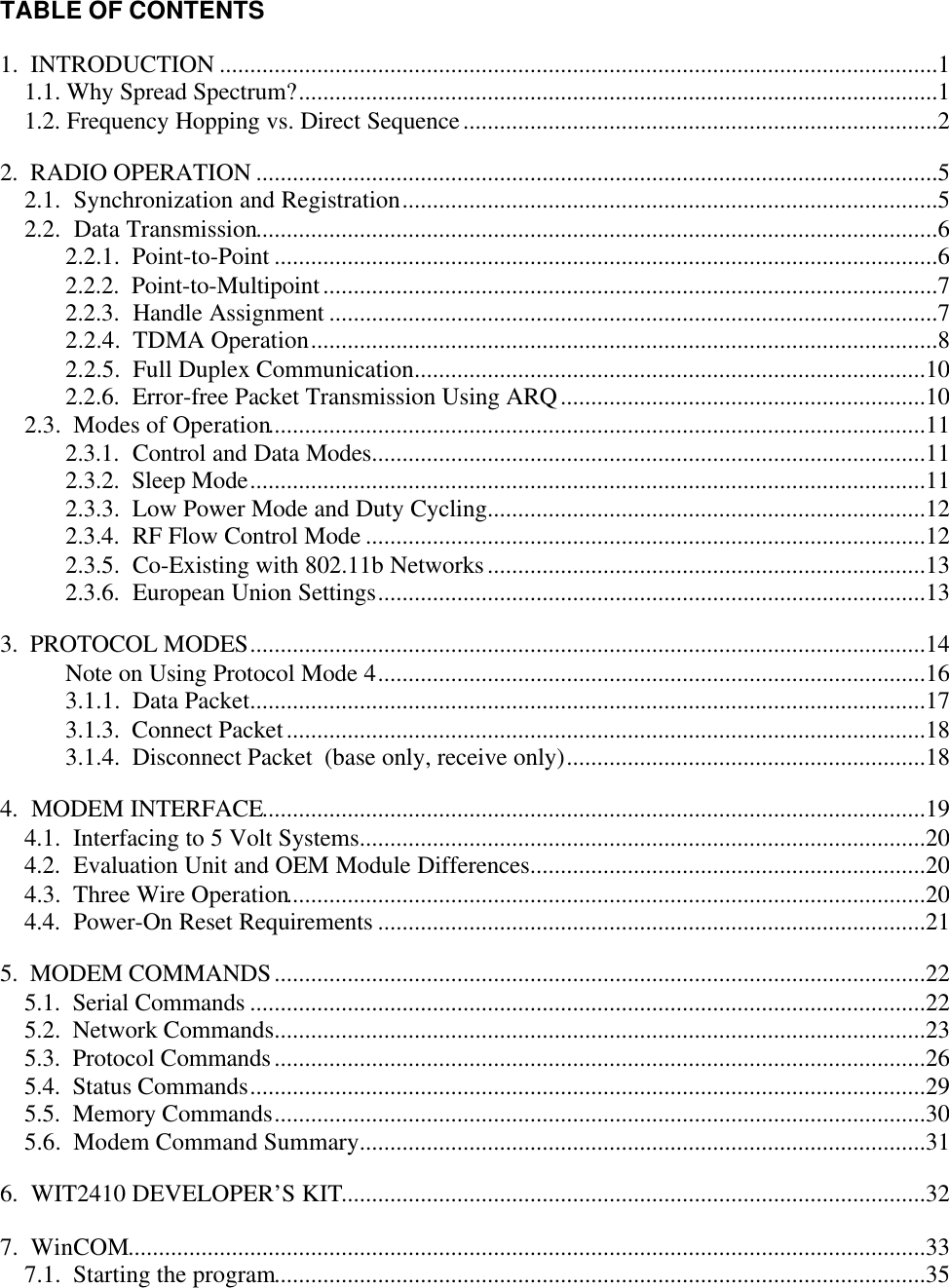
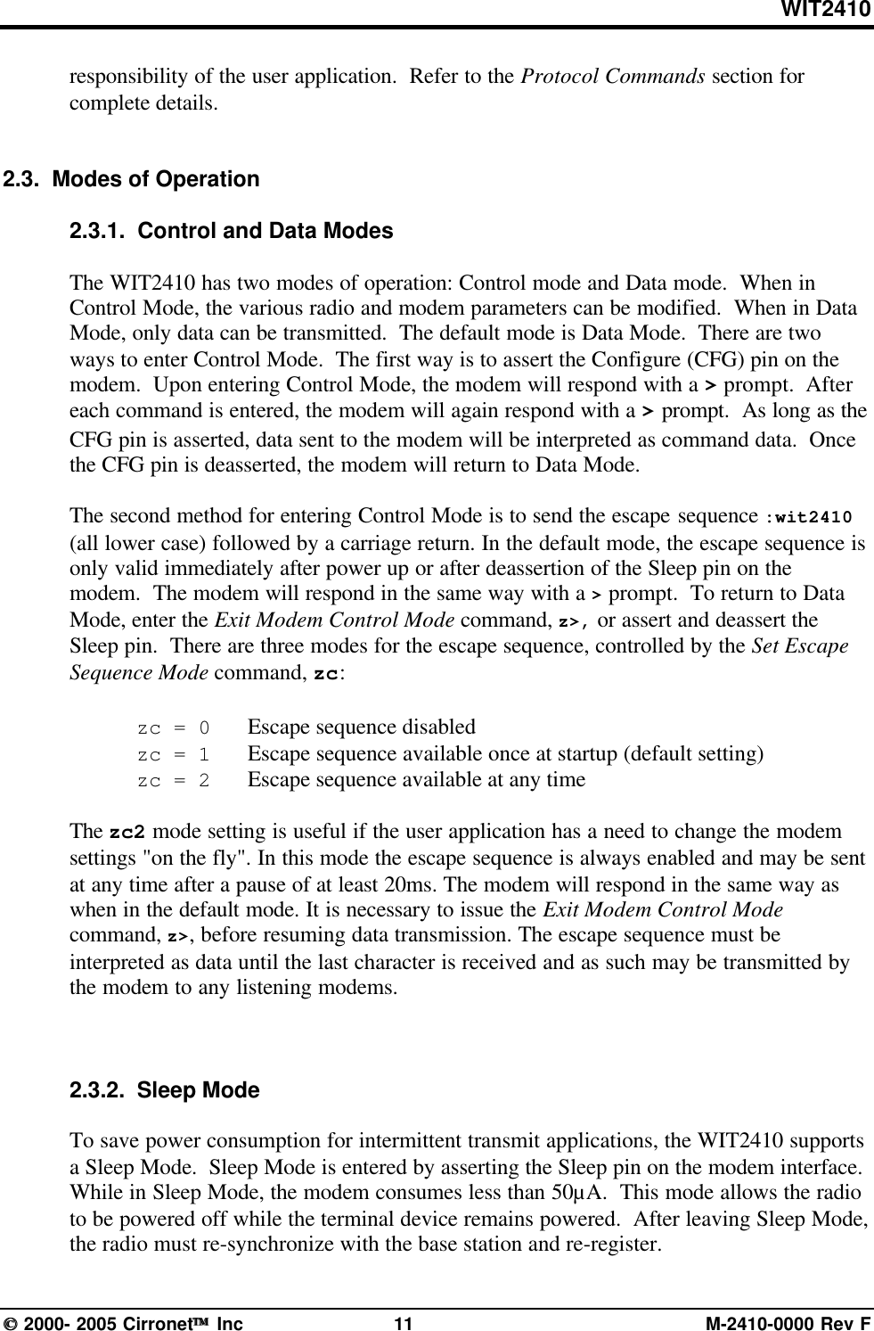
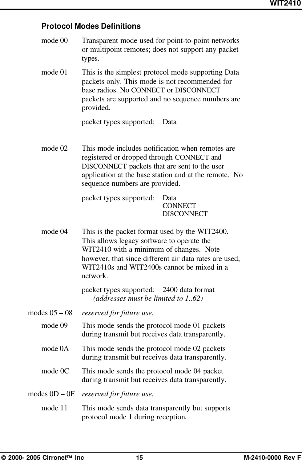
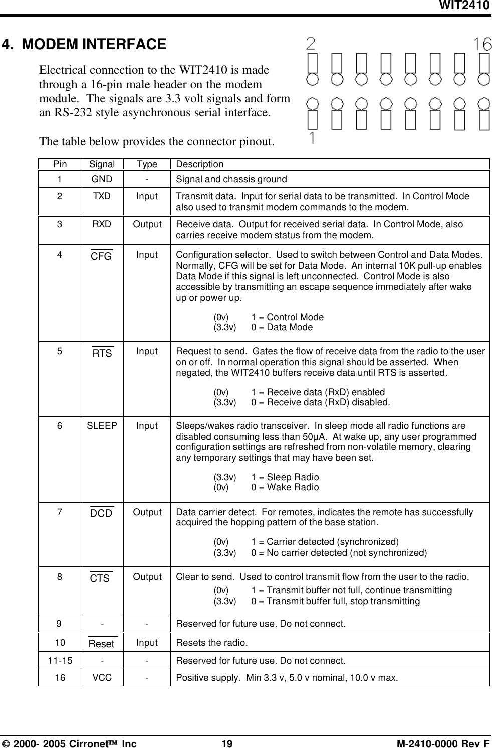
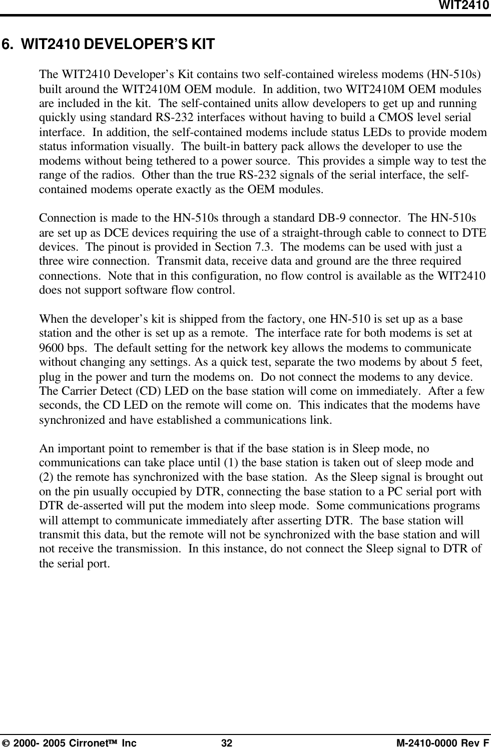
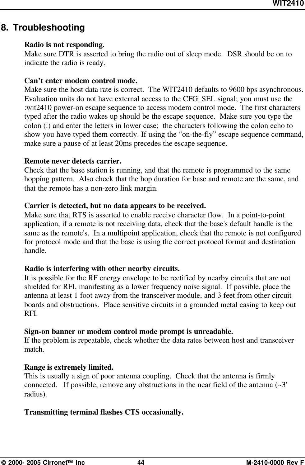
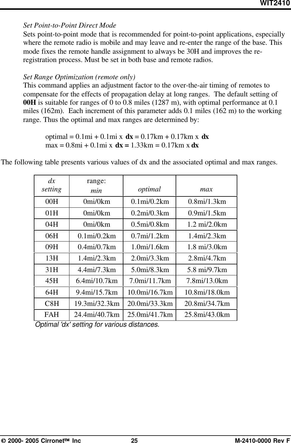
![WIT2410 2000- 2005 Cirronet Inc 22 M-2410-0000 Rev F5. MODEM COMMANDSThe WIT2410 is configured and controlled through a series of commands. Thesecommands are sent to the modem directly when the modem is in Control Mode when themodem is in Data Mode if the escape sequence is enabled. The command syntax is thesame for either method, a one- or two-letter command followed by one or moreparameters. The modem will respond with a two-byte message that indicates the newmodem parameter value. The commands are loosely grouped into five differentcategories: Serial commands, Network commands, Protocol commands, Statuscommands and Memory commands. Each command is described in detail below. In thedescriptions, brackets ([,]) are used to denote a set of optional arguments. Verticalslashes (|) separate selections. For example, given the string wn[?|0..3f], some legalcommands are wn?, wn0, wn3 and wna. Most commands which set a parameter also havea ? option which causes the modem to respond with the current parameter setting, e.g.,wn? Each modem command must be followed by either a carriage return or a line feed.5.1. Serial CommandsThese commands affect the serial interface between the modem and the host. The defaultsettings are 9600 bps and protocol mode 0.Command Descriptionsd[?|00..FF] Set Data Rate DivisorData Rate Divisor (hex)1200 bps =BF2400 bps =5F9600 bps =1714400 bps =0F19200 bps =0B28800 bps =0738400 bps =0557600 bps =03115200 bps =01230400 bps = 00sp[?|00..14] Set Protocol Mode00 =point-to-point transparent mode01 =basic command and data only02 =command, data and connection notification04 =WIT2400 protocol mode05 – 08 =reserved for future use09 =mode 01 during transmit, transparent receive0A =mode 02 during transmit, transparent receive0C =mode 04 during transmit, transparent receive0D – 10 =reserved for future use11 =transparent transmit, mode 01 during receive12 =transparent transmit, mode 02 during receive14 =transparent transmit, mode 04 during receive](https://usermanual.wiki/Murata-Electronics-North-America/2410G/User-Guide-652370-Page-28.png)
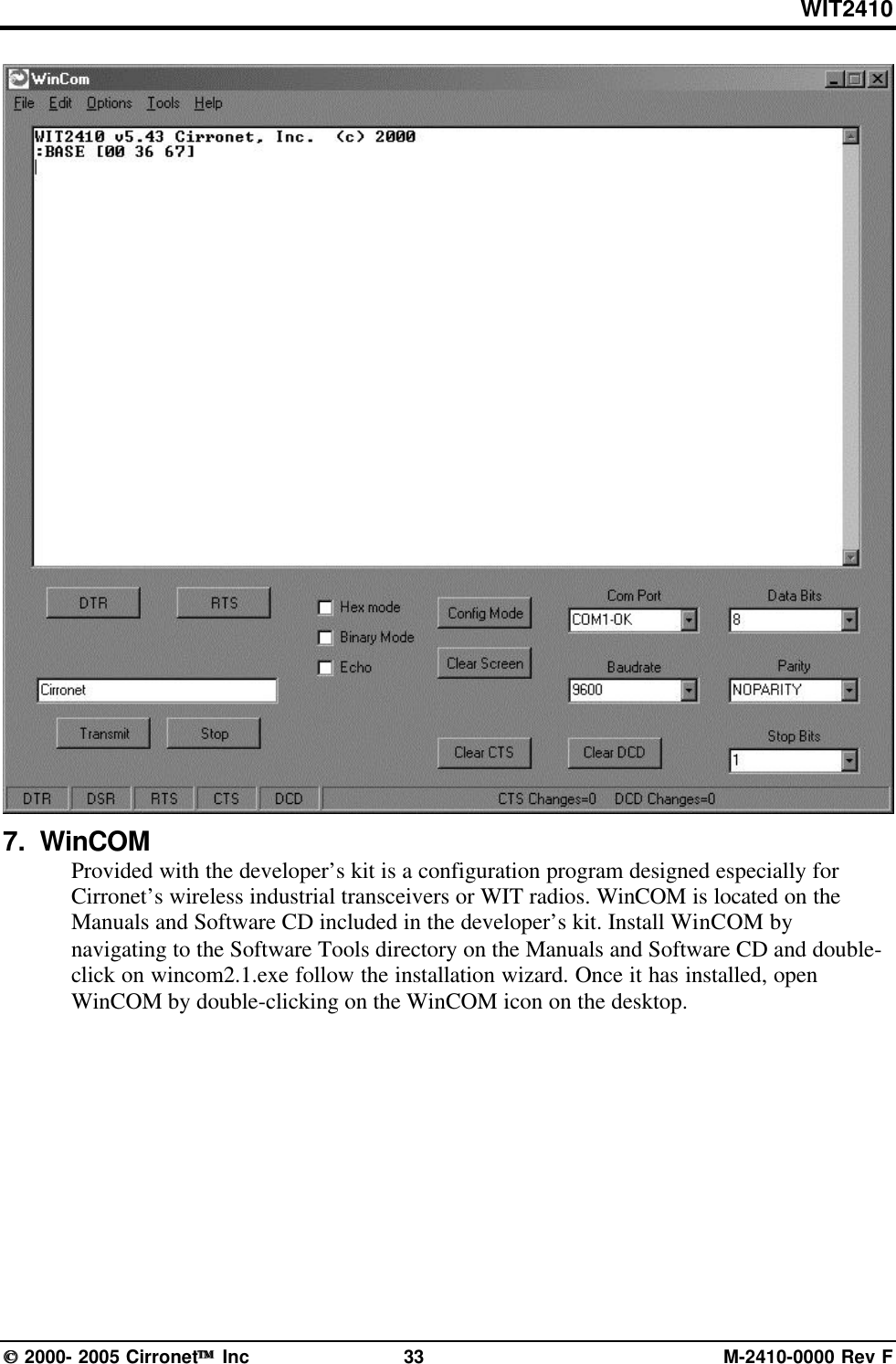
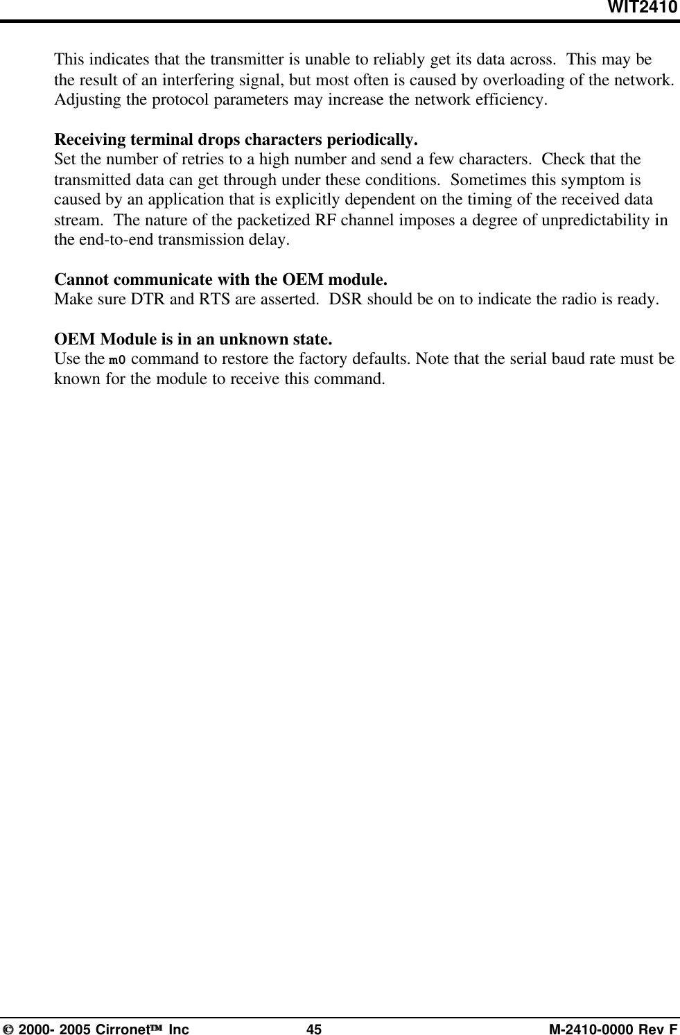
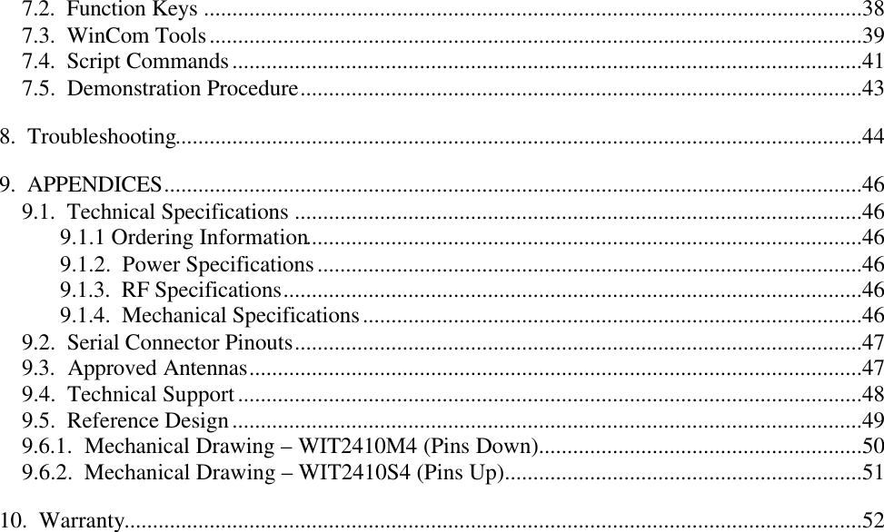
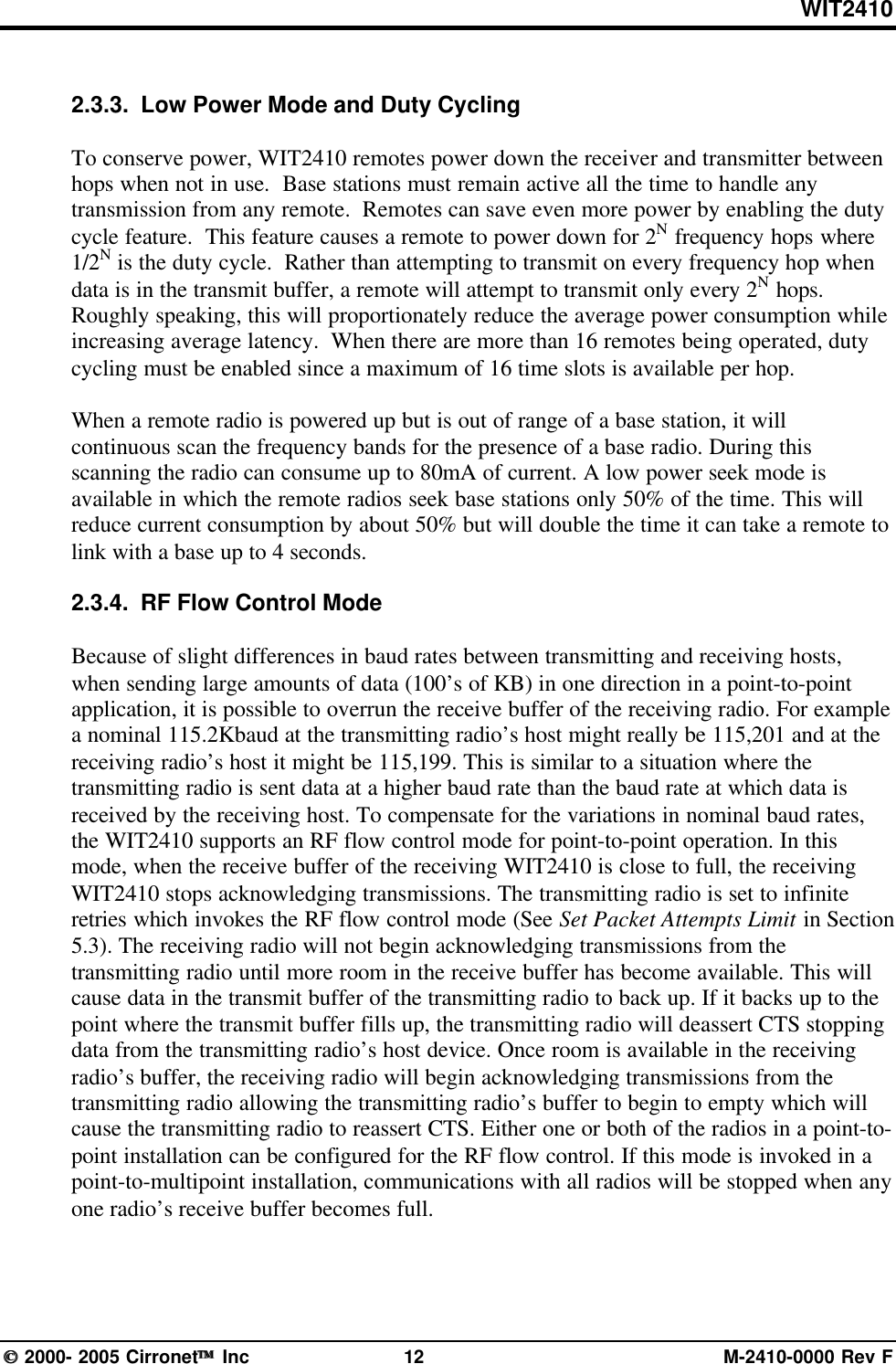
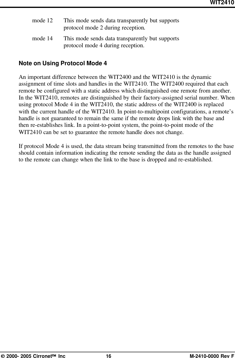
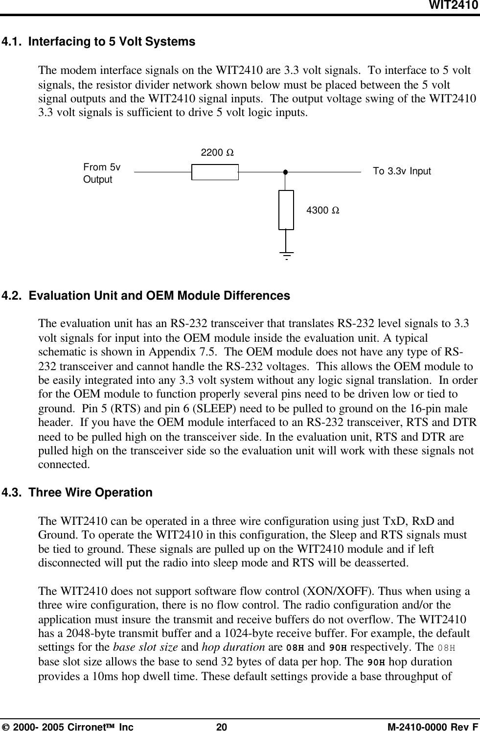
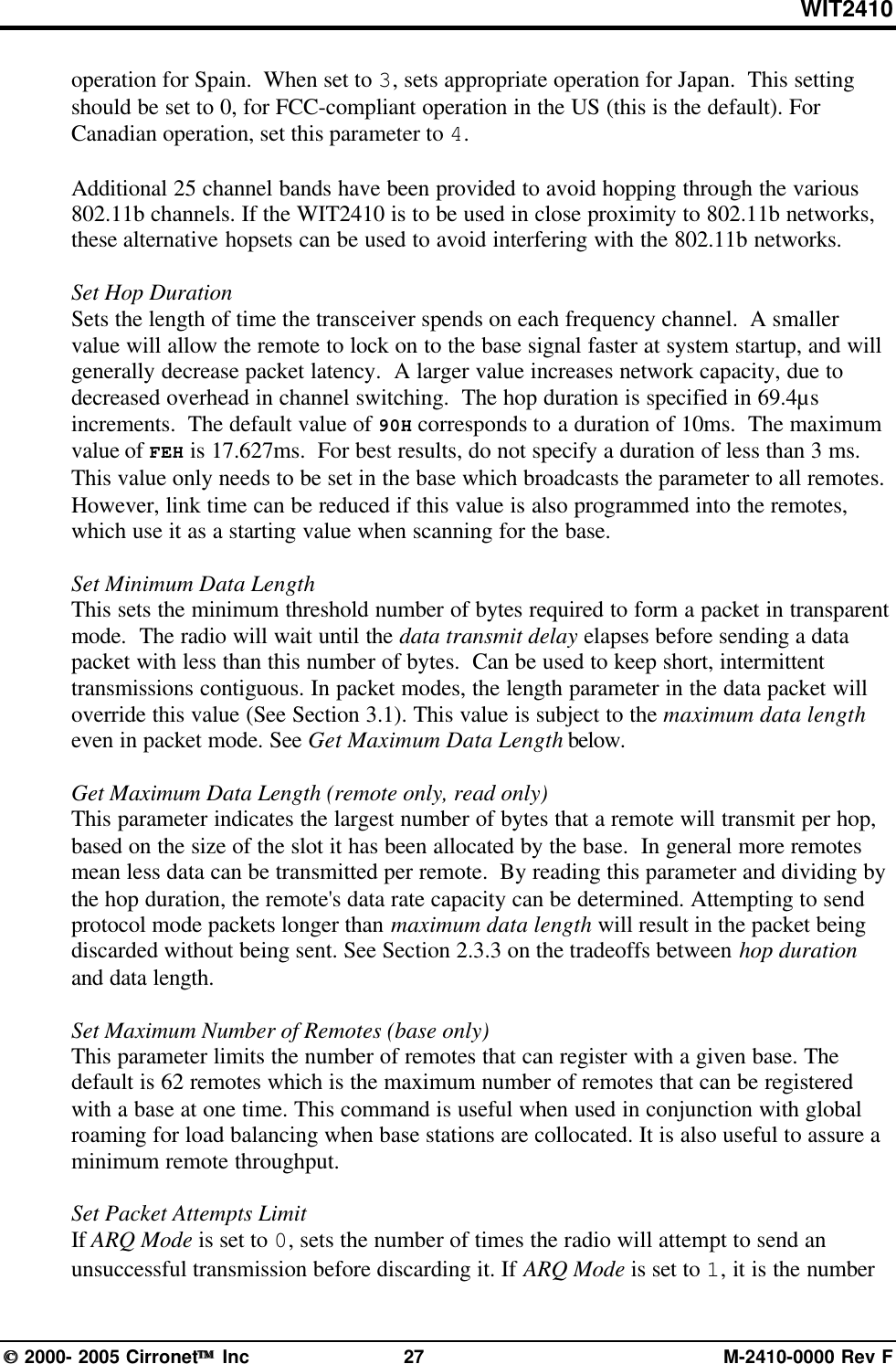
![WIT2410 2000- 2005 Cirronet Inc 23 M-2410-0000 Rev FSet Data Rate DivisorSets the serial bit rate between the modem and the host. This command takes effectimmediately and will require adjusting the host serial rate to agree. Nonstandard ratesmay be programmed by entering a data rate divisor computed with the following formula:DIVISOR = (230400/RATE)-1Round all non-integer values down.Set Protocol ModeEnables the base station to operate in a multipoint network. Depending on the userapplication, more or less acknowledgment may be desired by the application. Remotescan operate in transparent mode even though the base station is operating in one of thenontransparent modes.When using a protocol mode, make sure to count in packet overhead when calculatingnetwork performance. Refer to the section on Protocol Modes for details on each format.5.2. Network CommandsNetwork commands are used to set up a WIT2410 network and to set radio addressingand configuration.Command Descriptionwb[?|0|1] Set Transceiver Mode0 = remote (default)1 = base stationwd[?|1-3f] Set Default HandleUsed to override automatic handle assignment by the base station30 = defaultwg[?|0|1] Enable Global Network Mode0 = Link only to hop pattern specified by wn parameter (default)1 = Link to any hop pattern, regardless of wn parameterwl[?|0-ff] Set lockout key allowing network segregation beyond network number0 = defaultwn[?|0-3f] Set Hopping Pattern (Network Number)0 = defaultwp[?|0|1] Set Transmit Power0 = 10mW1 = 100mW (default)wr? Read Receive Signal Strengthwu[?|0|1] Set Point-to-Point Direct Mode0 = Multipoint mode (default)1 = Point-to-point direct modedx[?|0-ff](remote only) Set Range optimization0 = default](https://usermanual.wiki/Murata-Electronics-North-America/2410G/User-Guide-652370-Page-29.png)
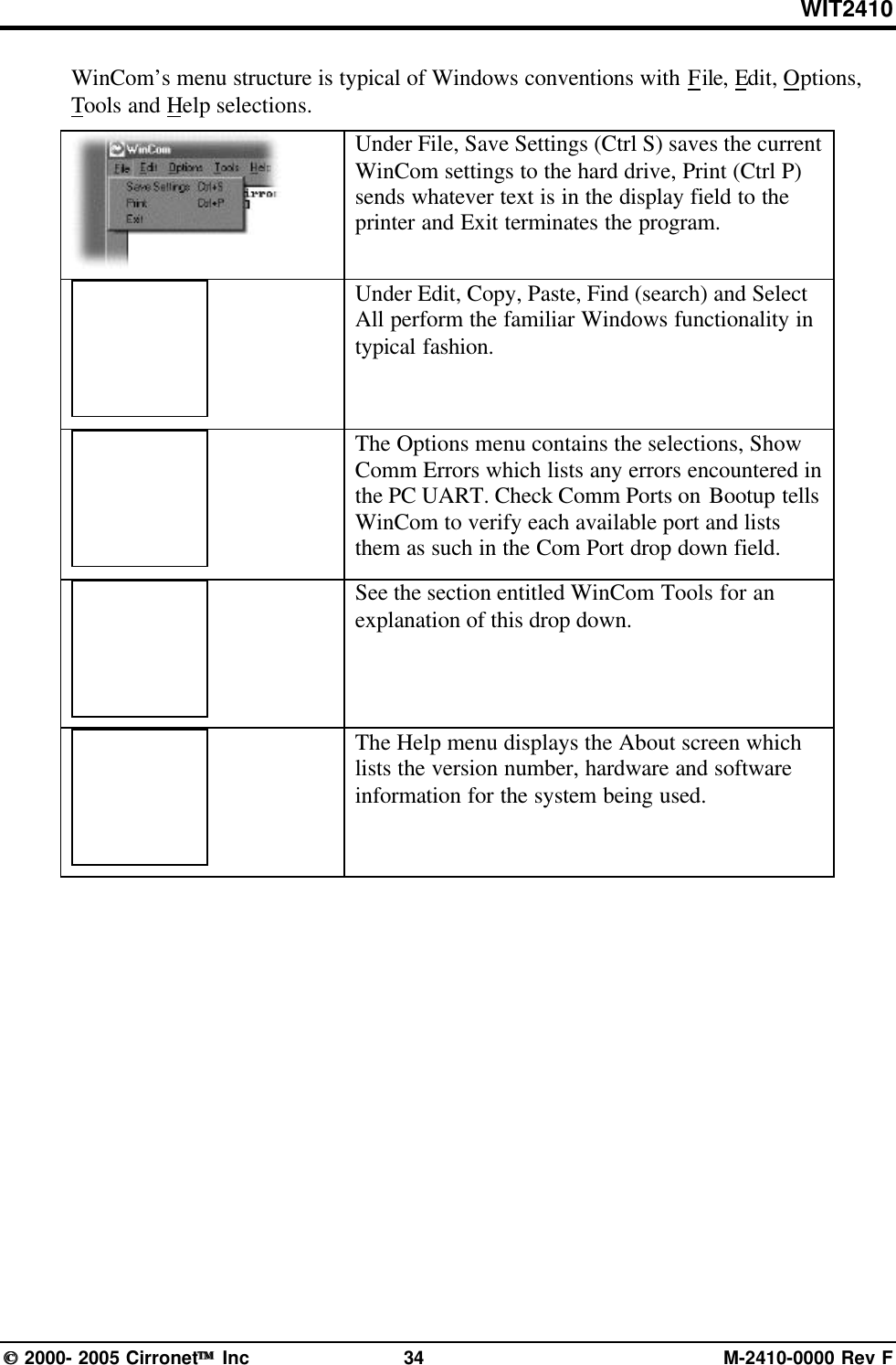
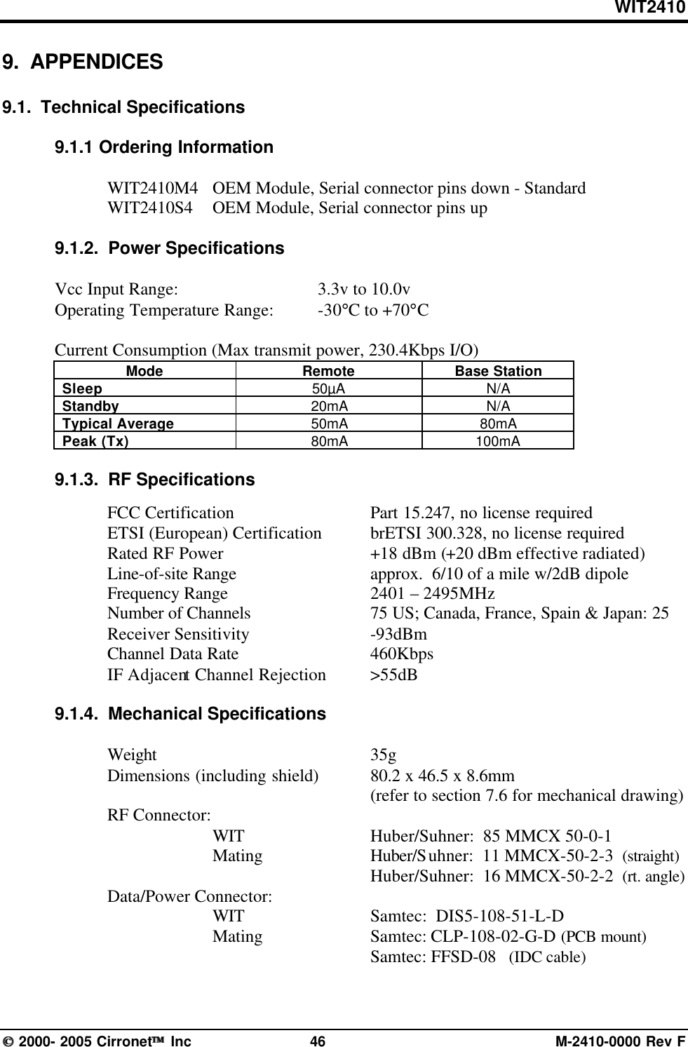
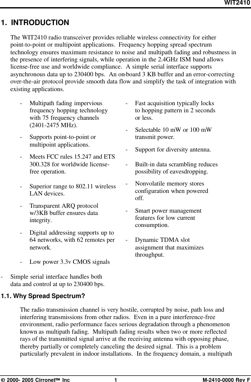
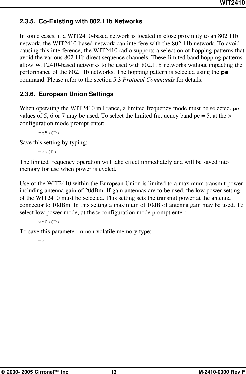
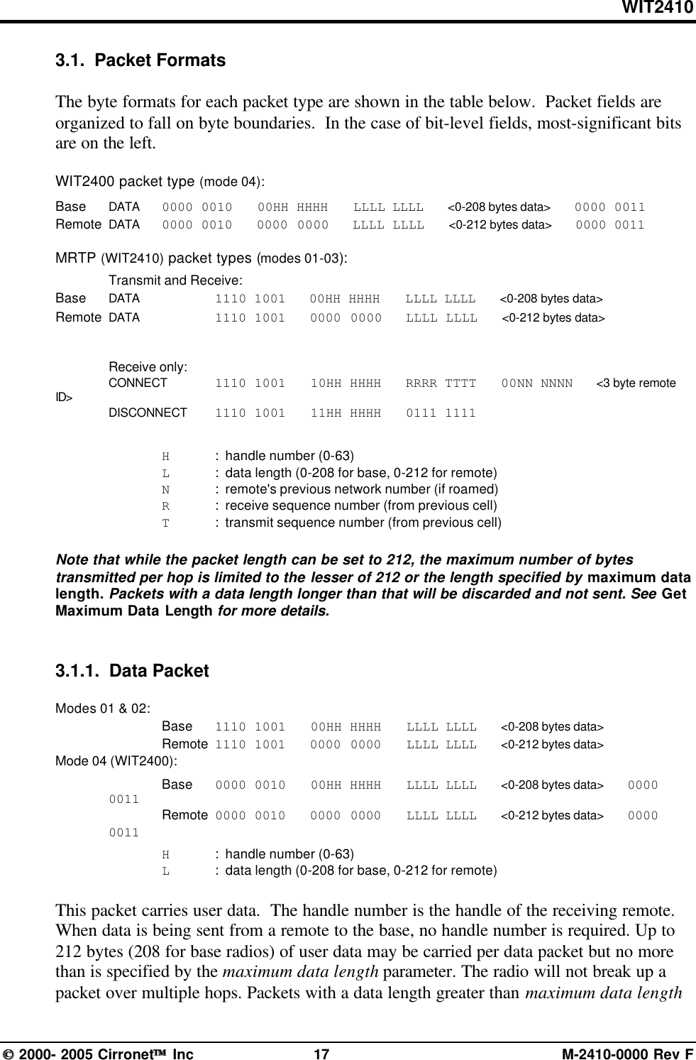
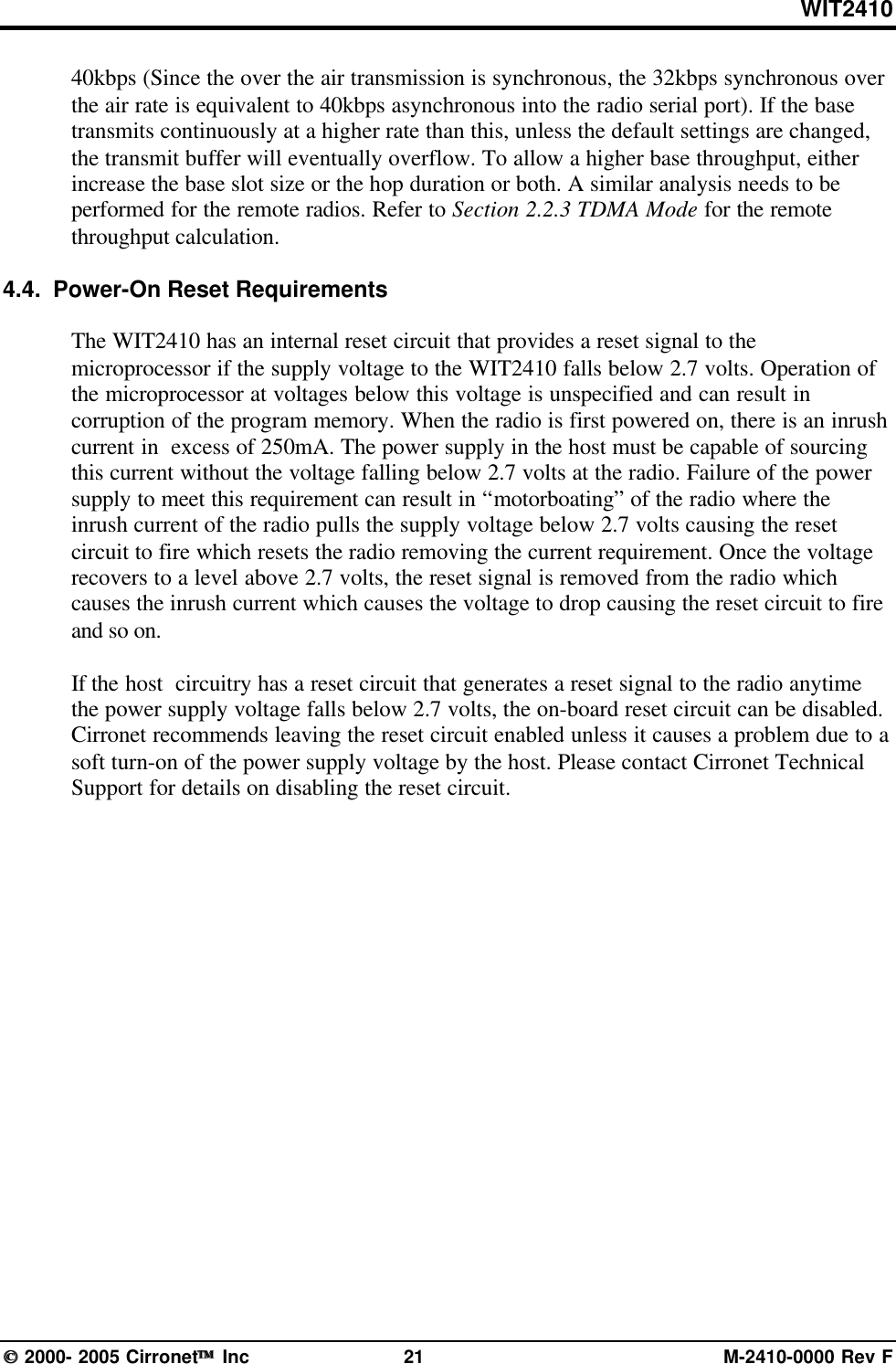
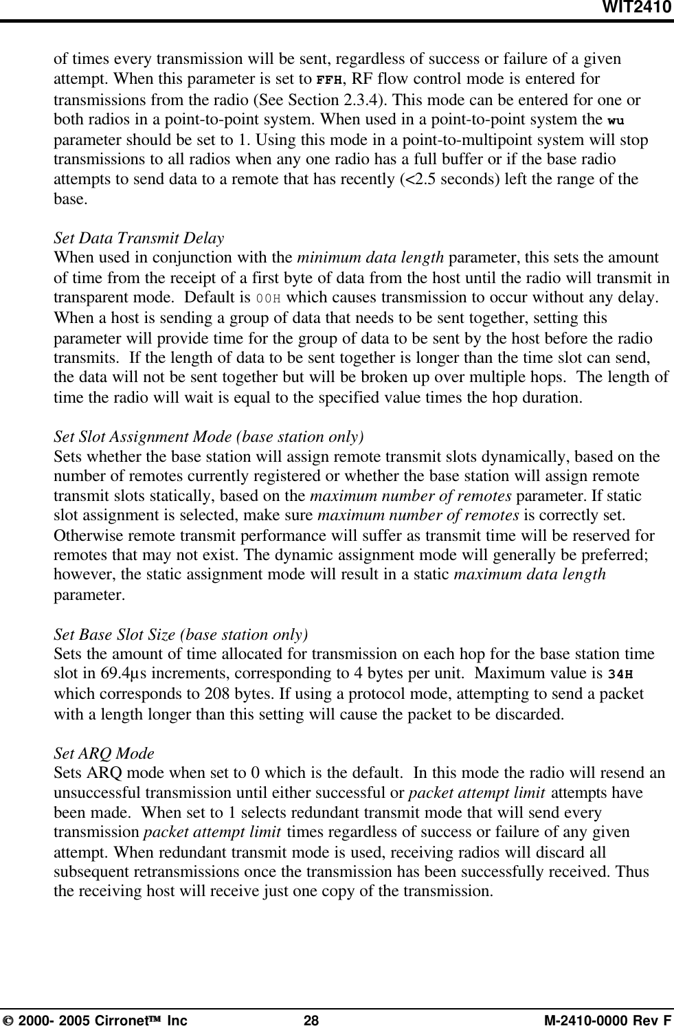
![WIT2410 2000- 2005 Cirronet Inc 26 M-2410-0000 Rev F5.3. Protocol CommandsThese commands can be used to tune the transceiver for optimum transmission of dataacross the RF link. For most applications, the default values are adequate.Command Descriptionpe[?|0-B] Set Alternative Frequency Band0 = USA operation. (~2400 – 2472MHz) (default)1 = ~2448 – 2474MHz, avoids 11b channels 1 – 6 & 142 = Spain (~2448 – 2474MHz), avoids 11b channels 1 – 6 & 143 = Japan (~2471 – 2497MHz), avoids 11b channels 1 - 104 = Canada (~2452 – 2477MHz), avoids 11b channels 1 – 6 & 145 = ~2400 – 2425MHz, avoids 11b channels 6 - 146 = ~2409 – 2435MHz, avoids 11b channels 8 - 147 = ~2419 – 2445MHz, avoids 11b channels 1 & 10 – 148 = ~2430 – 2455MHz, avoids 11b channels 1, 2 & 12 – 149 = ~2440 – 2465MHz, avoids 11b channels 1 – 4 & 14A = ~2449 – 2475MHz, avoids 11b channels 1 – 6 & 14B = ~2459 – 2485MHz, avoids 11b channels 1 – 7ph[?|00-fe](base only)Set Hop Duration90H = default (=10ms)pk[?|00-d0] Set Minimum Data Length01 = defaultpl?(remote only)Get Maximum Data Length (read only)D4 = default (=212 bytes)pn[?|01-3e](base only) Set Maximum Number of Remotes3e = default (=62 remotes)pr[?|00-ff] Set Packet Attempts Limit10H = defaultFFH = Infinite retry (RF flow control point-to-point only)pt[?|00-ff] Set Data Transmit Delay00H = defaultpv[?|0|1](base only)Set Slot Assignment Mode0 = default (dynamic slot assignment)1 = static slot assignmentpw[?|00-34](base only) Set Base Slot Size08H = default (=32 bytes)px[?|0|1] Set ARQ mode.0 = ARQ enabled (default)1 = ARQ disabled (redundant transmission)Note: Incorrect setting of these parameters may result in reduced throughput or loss of data packets.Set Alternative Frequency BandWhen set to 1, limits the operating RF channel set to the 2448 to 2473MHz frequencyband for compliance with French regulatory standards. When set to 2, sets appropriate](https://usermanual.wiki/Murata-Electronics-North-America/2410G/User-Guide-652370-Page-32.png)
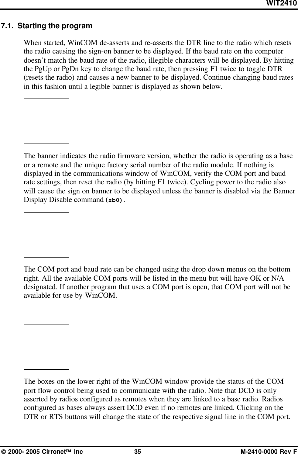
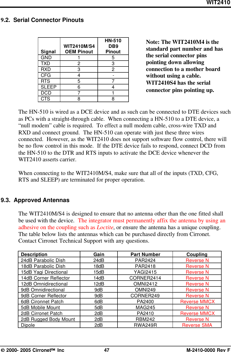
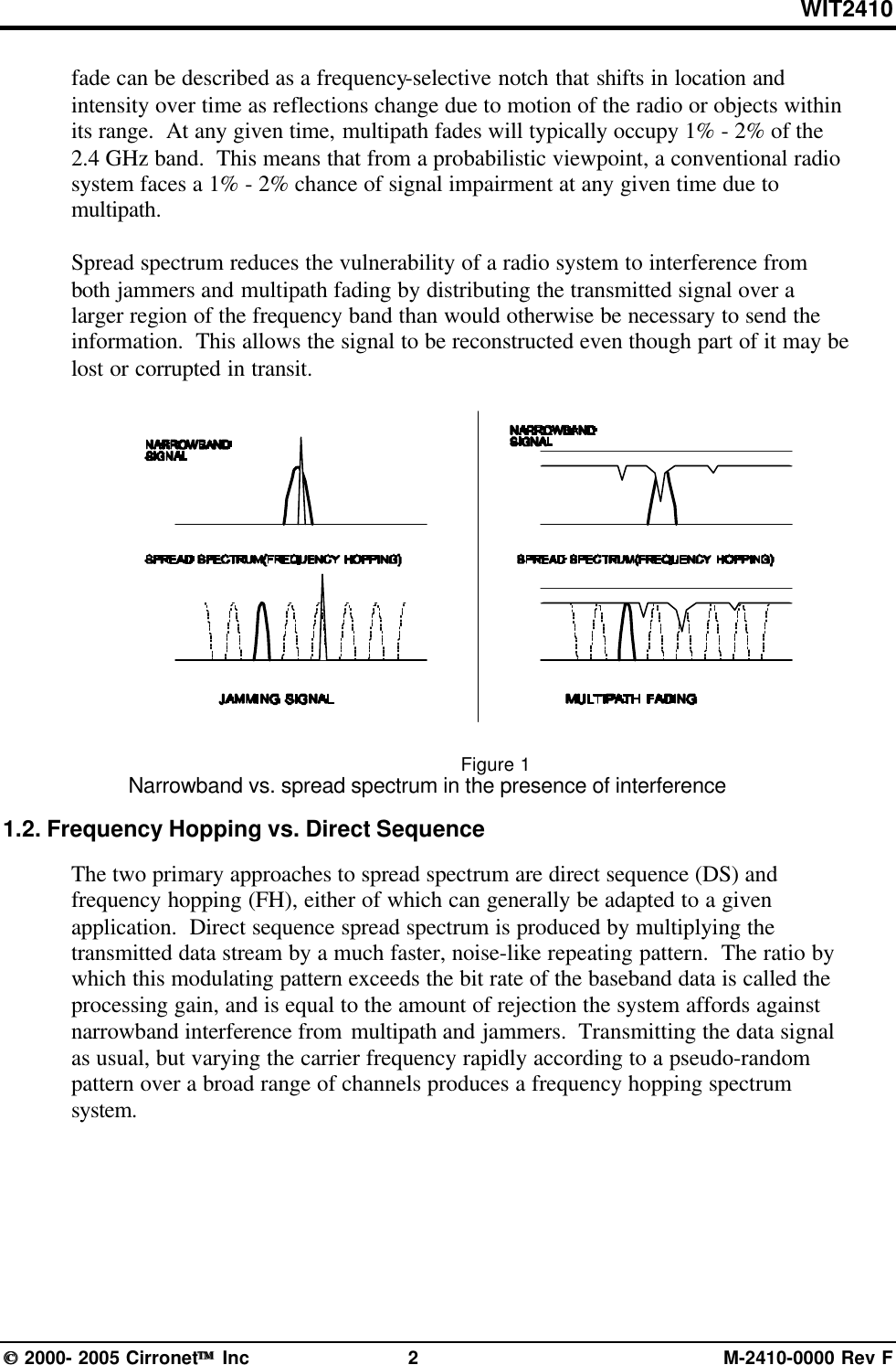
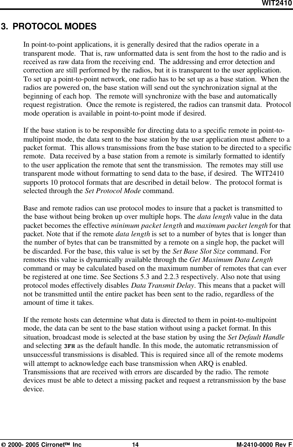
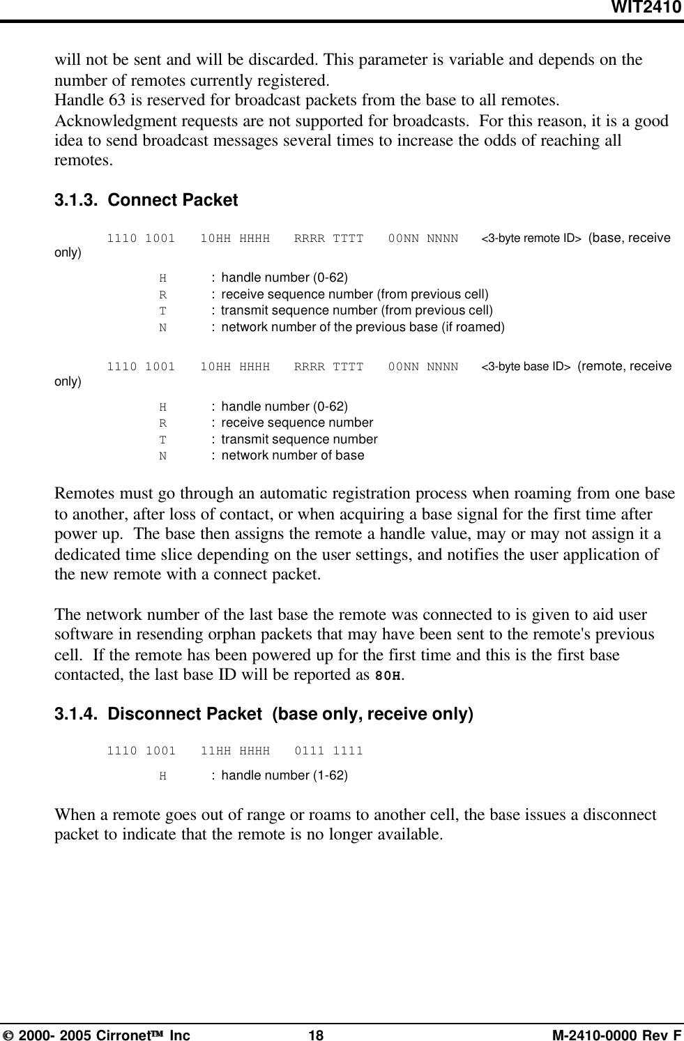
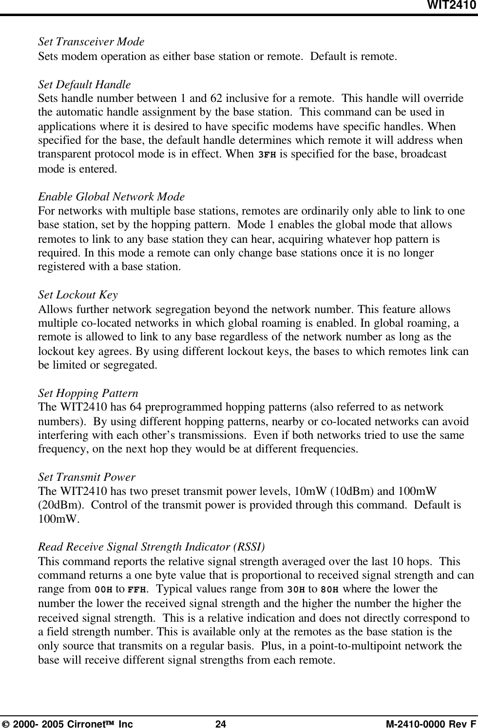
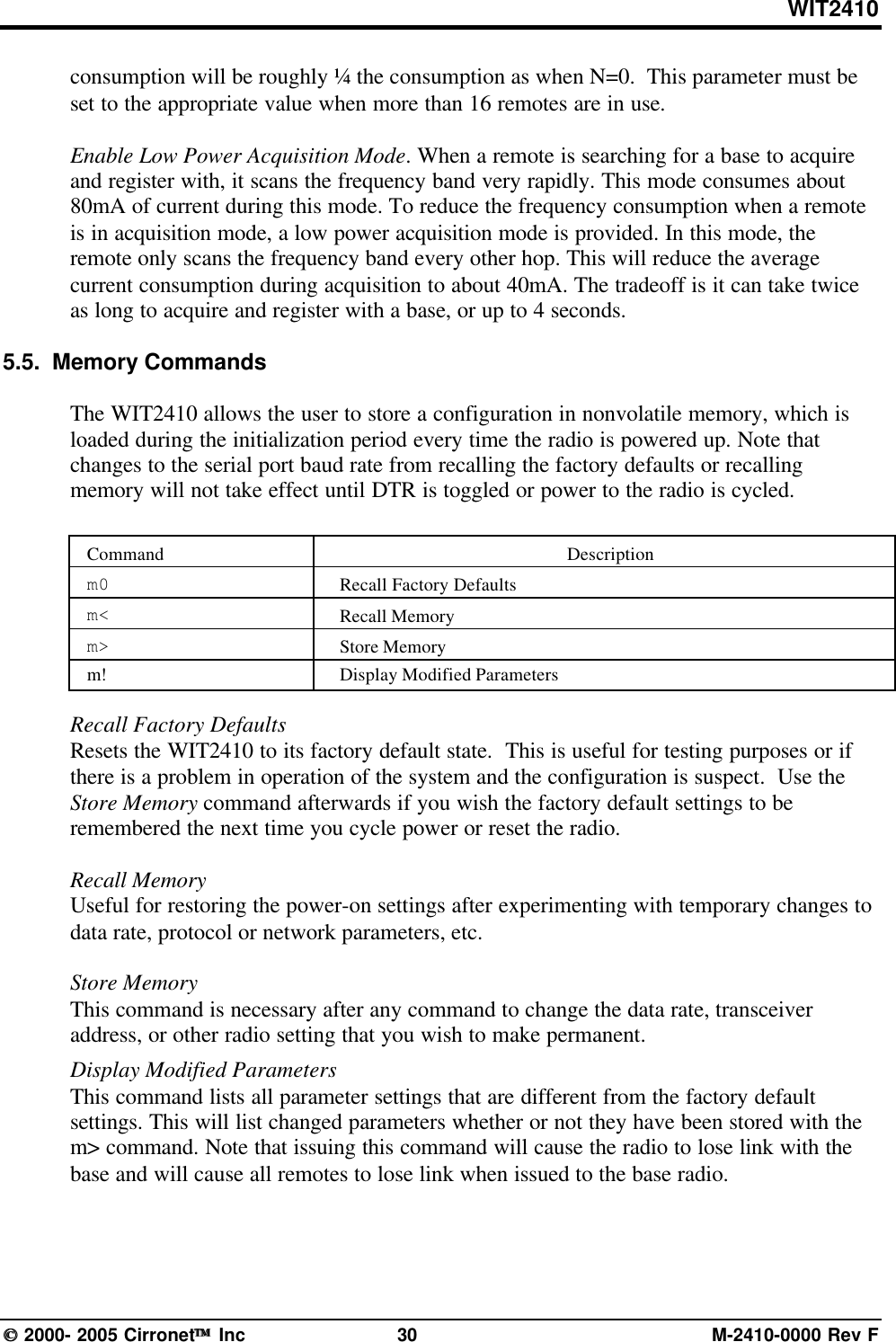
![WIT2410 2000- 2005 Cirronet Inc 29 M-2410-0000 Rev F5.4. Status CommandsThese commands deal with general interface aspects of the operation of the WIT2410.Command Descriptionzb[?|0|1] Banner Display Disable0 = disabled1 = enabled (default)zc[?|0..2] Set Escape Sequence Mode0 = disabled1 = once after reset (default)2 = unlimited timeszh? Read factory serial number high byte.zm? Read factory serial number middle byte.zl? Read factory serial number low byte.zp[?|0-4] Set the duty cycle at which the modem will wake up to send and receive data.Duty cycle equals 1/2N where the argument of the command equals N.zq[?|0|1](remote only)Low Power Acquisition Mode Enable0 = Disabled (default)1 = Enabledz> Exit Modem Control ModeBanner Display DisableEnables or disables display of the banner string and revision code automatically at power-up. May be disabled to avoid being mistaken for data by the host.Set Escape Sequence ModeEnables or disables the ability to use the in-data-stream escape sequence method ofaccessing Control Mode by transmitting the string ":wit2410". When this mode is setto 1, the escape sequence only works immediately after reset (this is the default). Whenset to 2, the escape sequence may be used at any time in the data stream when precededby a pause of 20 ms. For backwards compatibility with the WIT2400, the string":wit2400" is also accepted for entering Control Mode. Note that the escape sequencemust be interpreted as data by the radio until the last character is received, and as suchwill be generally be transmitted to a receiving radio station, if any.Read Factory Serial Number High, Middle and Low Bytes.These read only commands return one of the three bytes of the unique factory-set serialnumber, which are also visible in the startup banner.Set Duty CycleAllows reduced power consumption by having a remote wake up only every 2N hops toreceive and transmit. Power consumption is roughly proportional to the duty cycleselected. For example, if N=2, the remote will wake up every fourth hop. Power](https://usermanual.wiki/Murata-Electronics-North-America/2410G/User-Guide-652370-Page-35.png)
![WIT2410 2000- 2005 Cirronet Inc 31 M-2410-0000 Rev F5.6. Modem Command SummarySerial Commandssd[?|00..ff] Set Data Rate Divisorsp[?|00..14] Set Protocol ModeNetwork Commandswb[?|0|1] Set Transceiver Modewd[?|1..3f] Set Default Handlewl[?|0..ff] Set Lockout Keywn[?|00..3f] Set Hopping Patternwg[?|0|1] Enable Global Network Modeswp[?|0|1] Set Transmit Powerwr? Read Receive Signal Strength (remote only)wu[?|0|1] Set Point-to-Point Direct Modedx[?|0..62] Set Range Optimization (base only)Protocol Commandspe[?|0..4] Set Alternative Frequency Bandph[?|00..fe] Set Hop Duration (base only)pl? Get Maximum Data Length (remote only, read only)pn[?|01..3e] Set Maximum Number of Remotes (base only)pk[?|00..d4] Set Minimum Data Lengthpr[?|00..ff] Set Packet Attempts Limitpt[?|00..ff] Set Data Transmit Delay (remote only)pv[?|0|1] Set Slot Assignment Mode (base only)pw[?|00..34] Set Base Slot Size (base only)px[?|0|1] Set ARQ ModeStatus Commandszb[?|0|1] Banner Display Disablezc[?|0..2] Set Escape Sequence Modezh? Read Factory Serial Number High Bytezm? Read Factory Serial Number Middle Bytezl? Read Factory Serial Number Low Bytezp[?|0..4] Set Duty Cyclezq[?|0|1] Enable Low Power Acquisition (remote only)z> Exit Modem Control ModeMemory Commandsm0 Recall Factory Defaultsm< Recall Memorym> Store Memorym! Display Changed ParametersNote: Brackets ([,]) as used here denote a set of optional arguments. Vertical slashes separate selections.For example, given the string wn[?|00..3f], legal commands would be wn?, wn0, wn3, and wn2a.Most commands which set a parameter also have a ? option which displays the current parameter setting;e.g., wn?.](https://usermanual.wiki/Murata-Electronics-North-America/2410G/User-Guide-652370-Page-37.png)