Murata Electronics North America DNT24 Spread Spectrum Wireless Transceiver User Manual Rev 2
Murata Electronics North America Spread Spectrum Wireless Transceiver Users Manual Rev 2
Contents
- 1. manual pt 1
- 2. manual pt 2
- 3. Users Manual Rev 2
Users Manual Rev 2
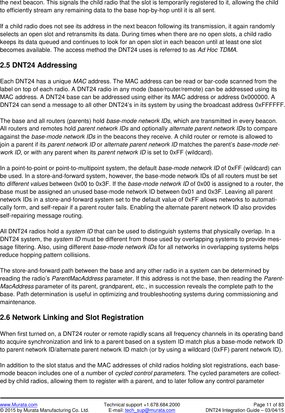
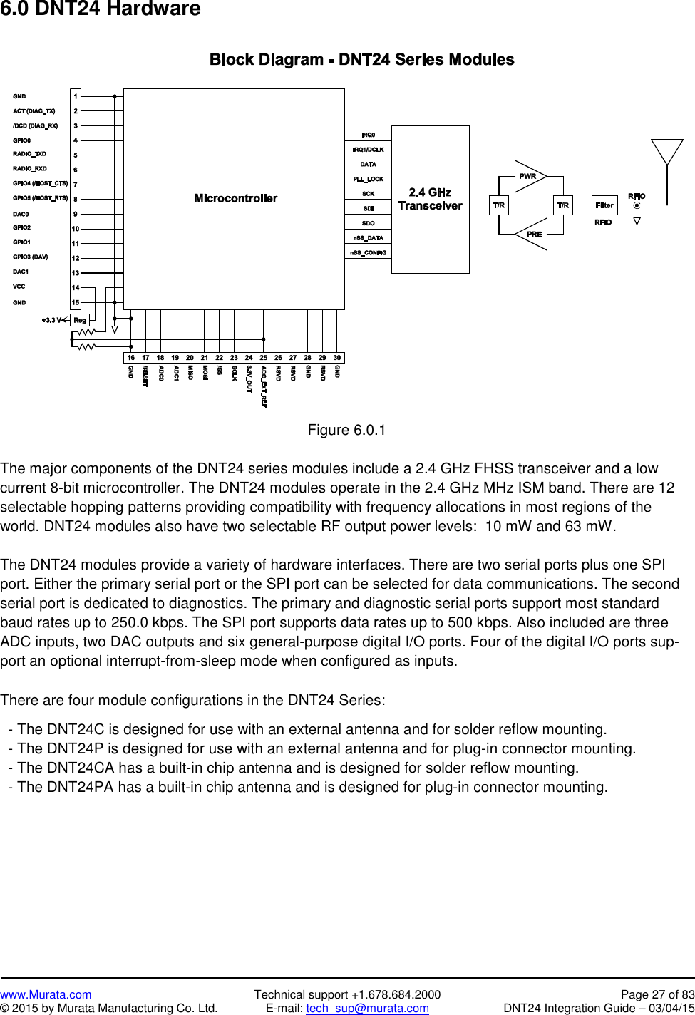
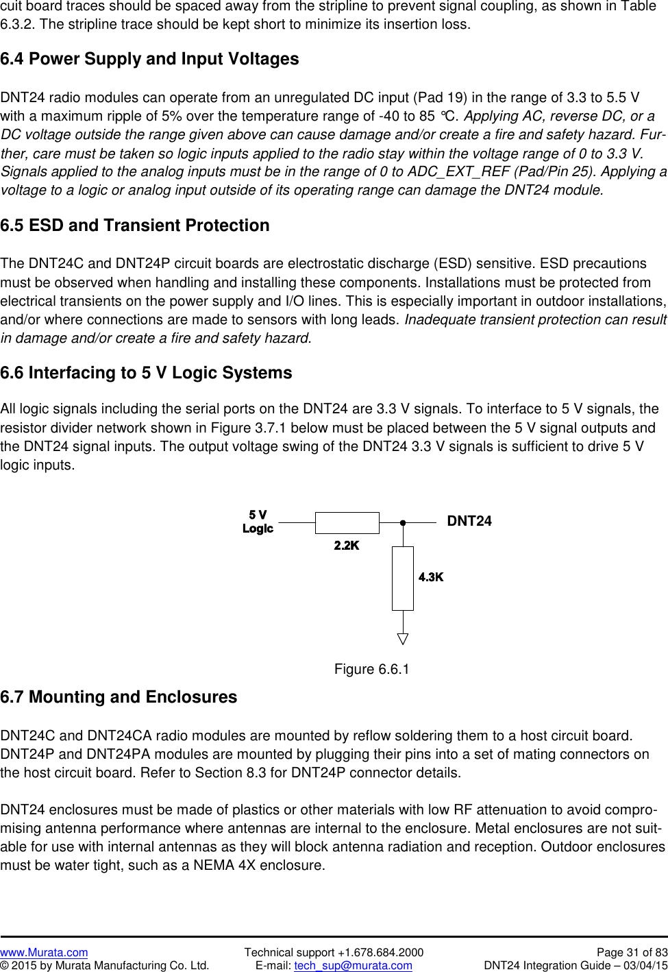
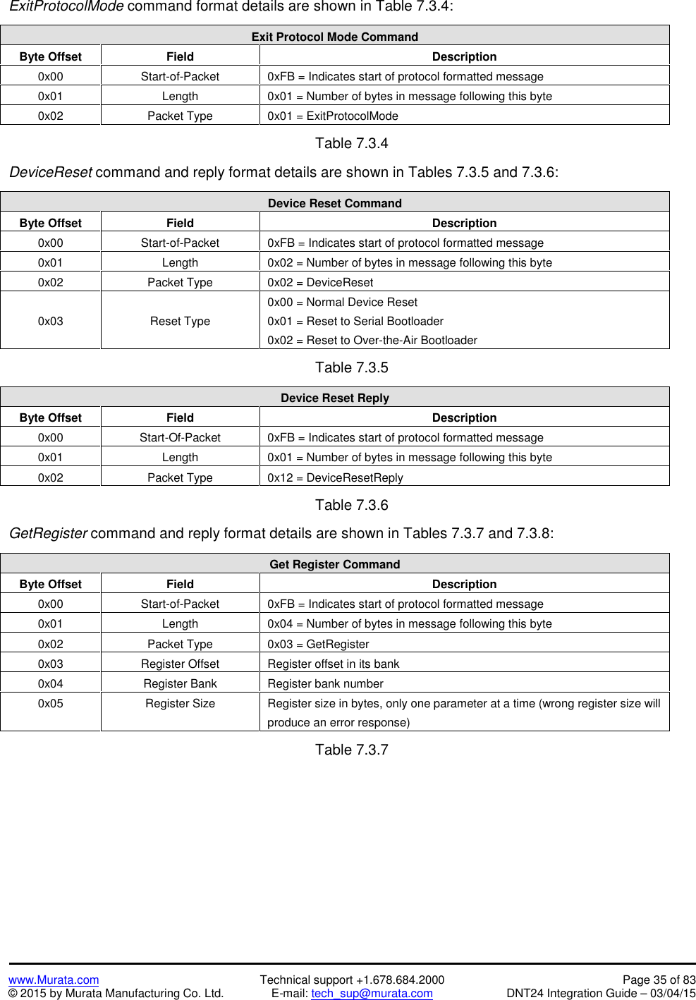
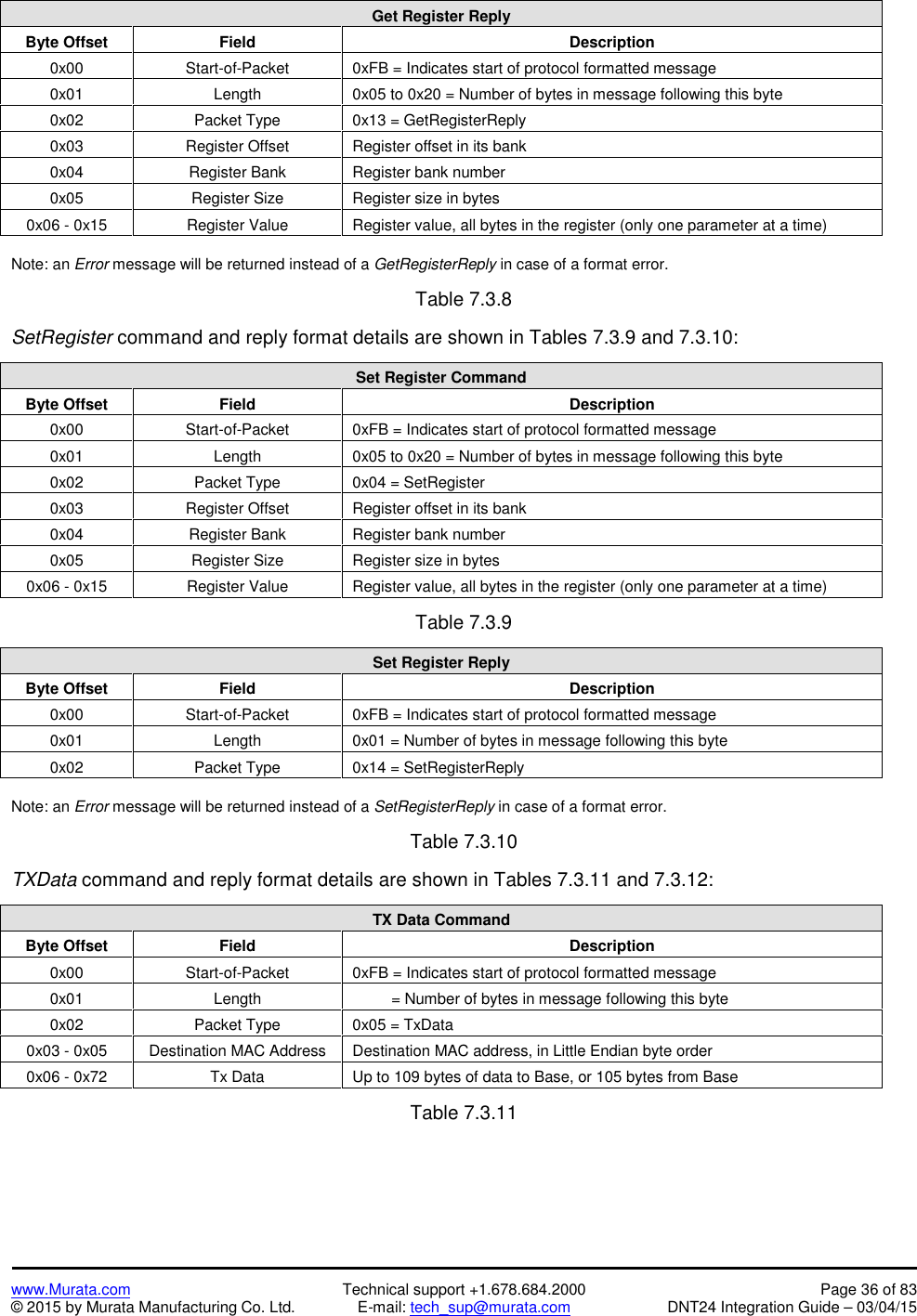
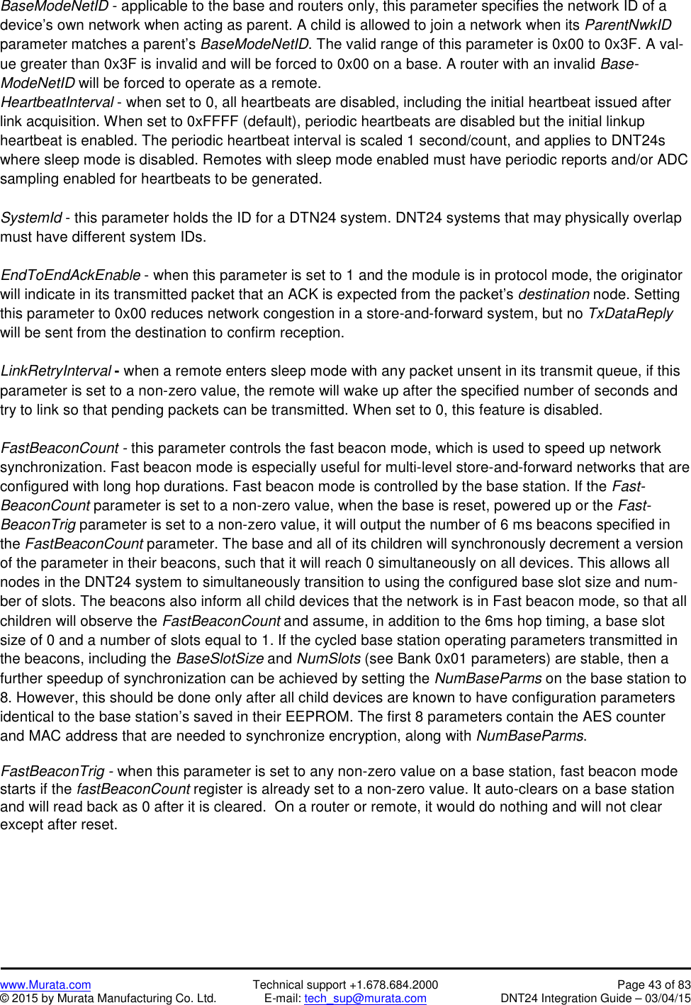
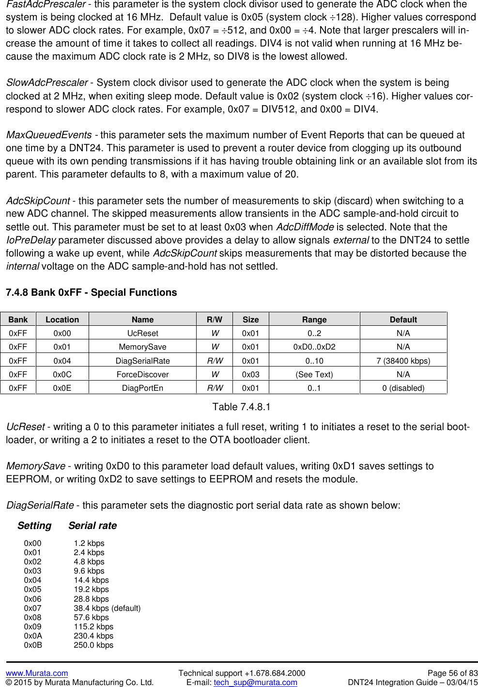
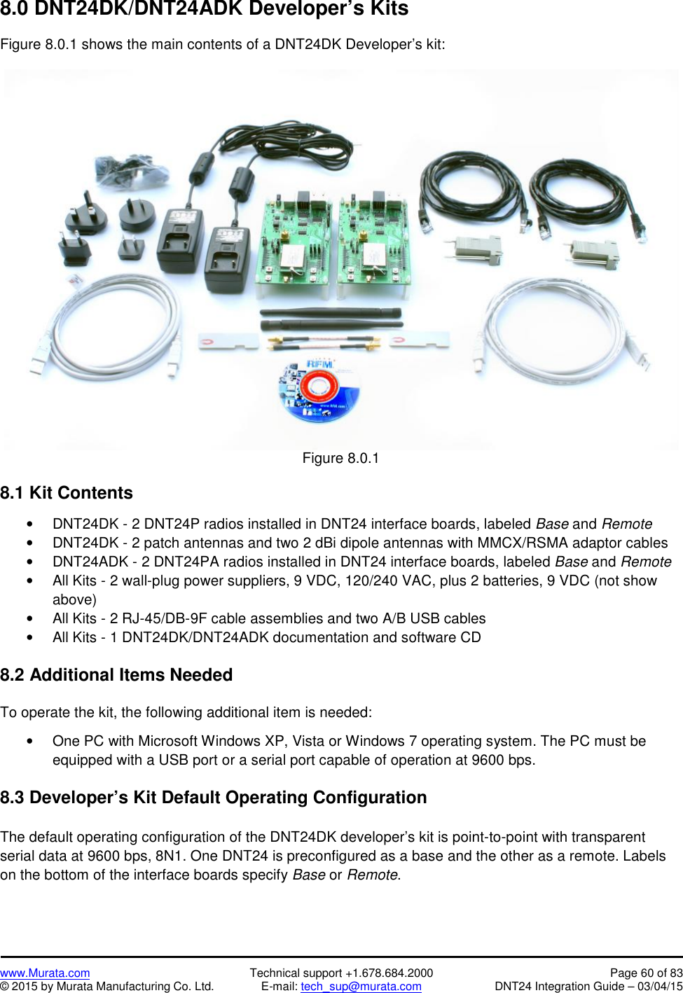

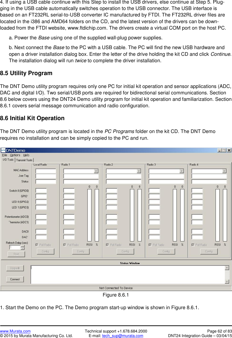
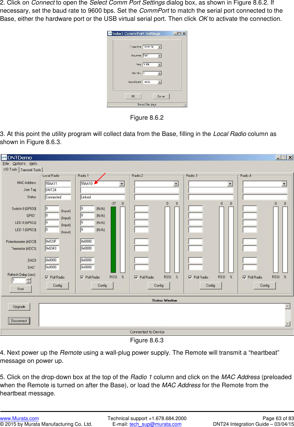
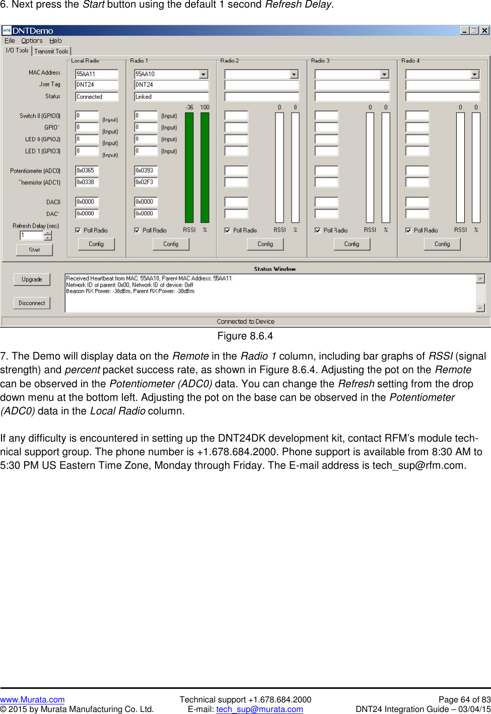
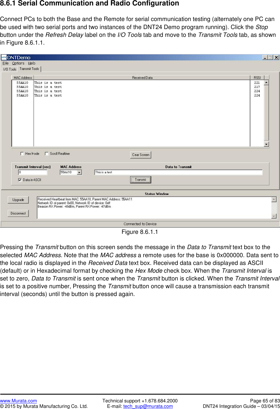
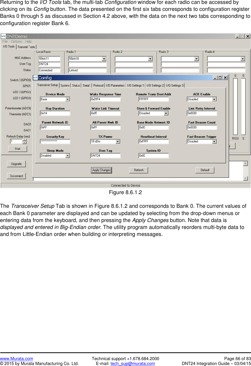
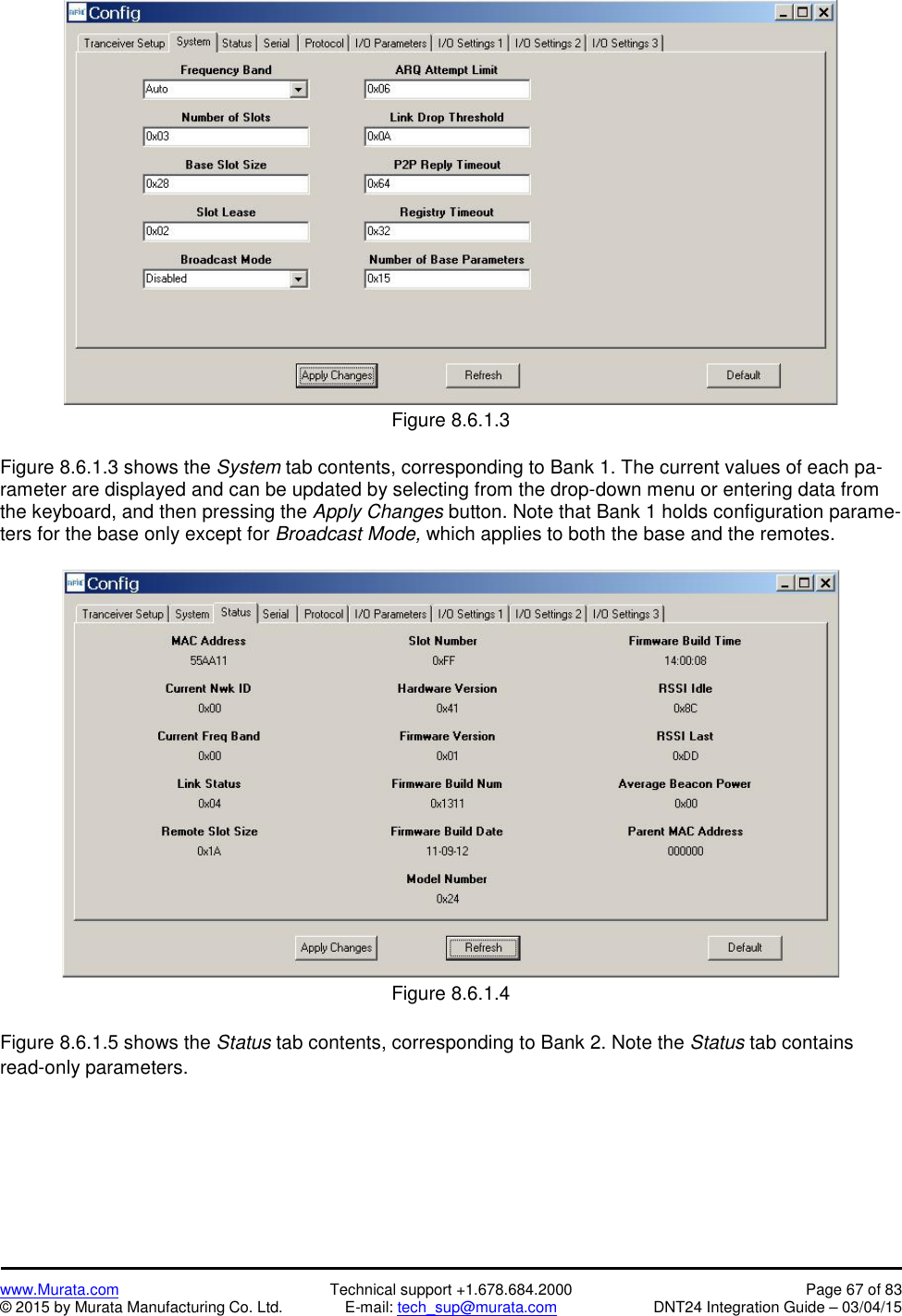
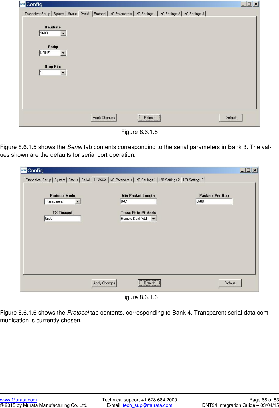
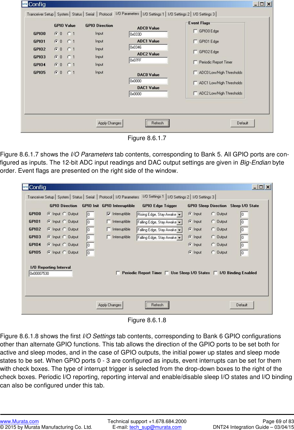
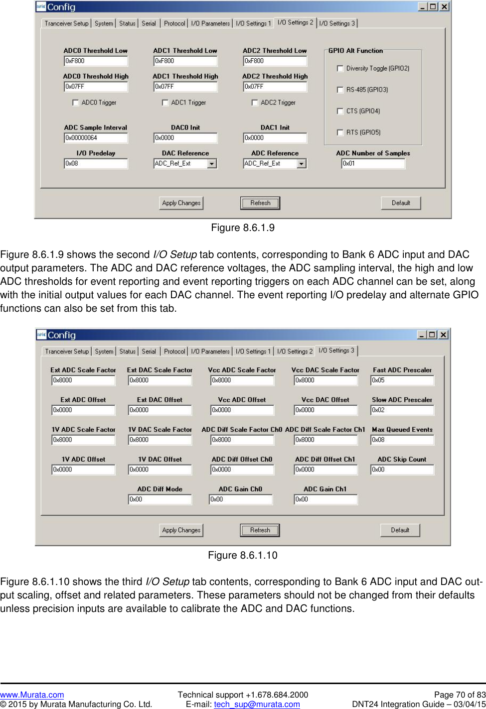
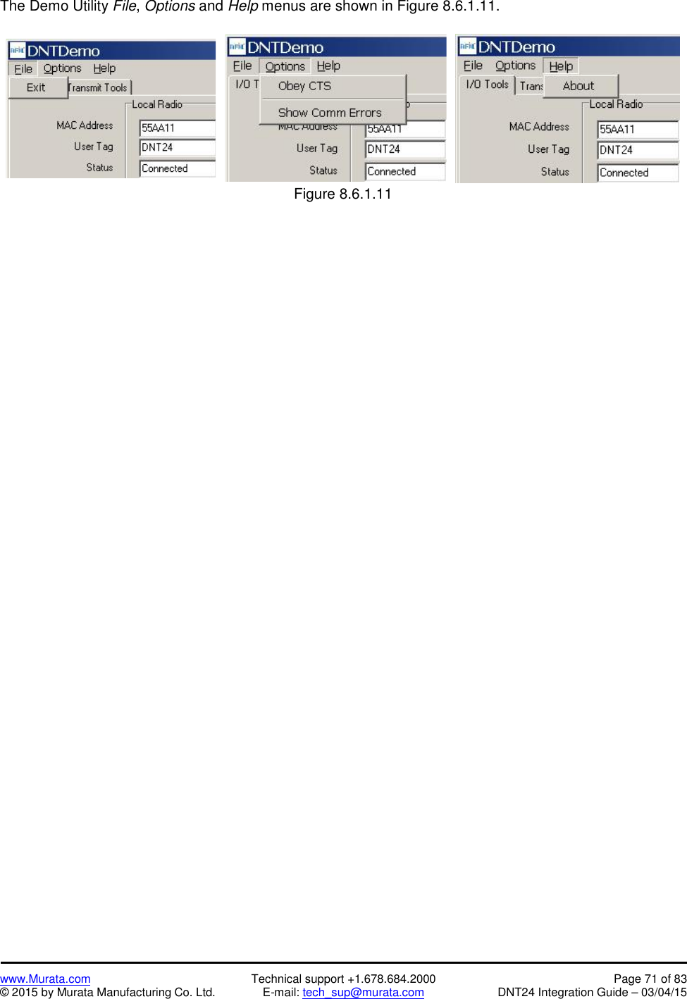
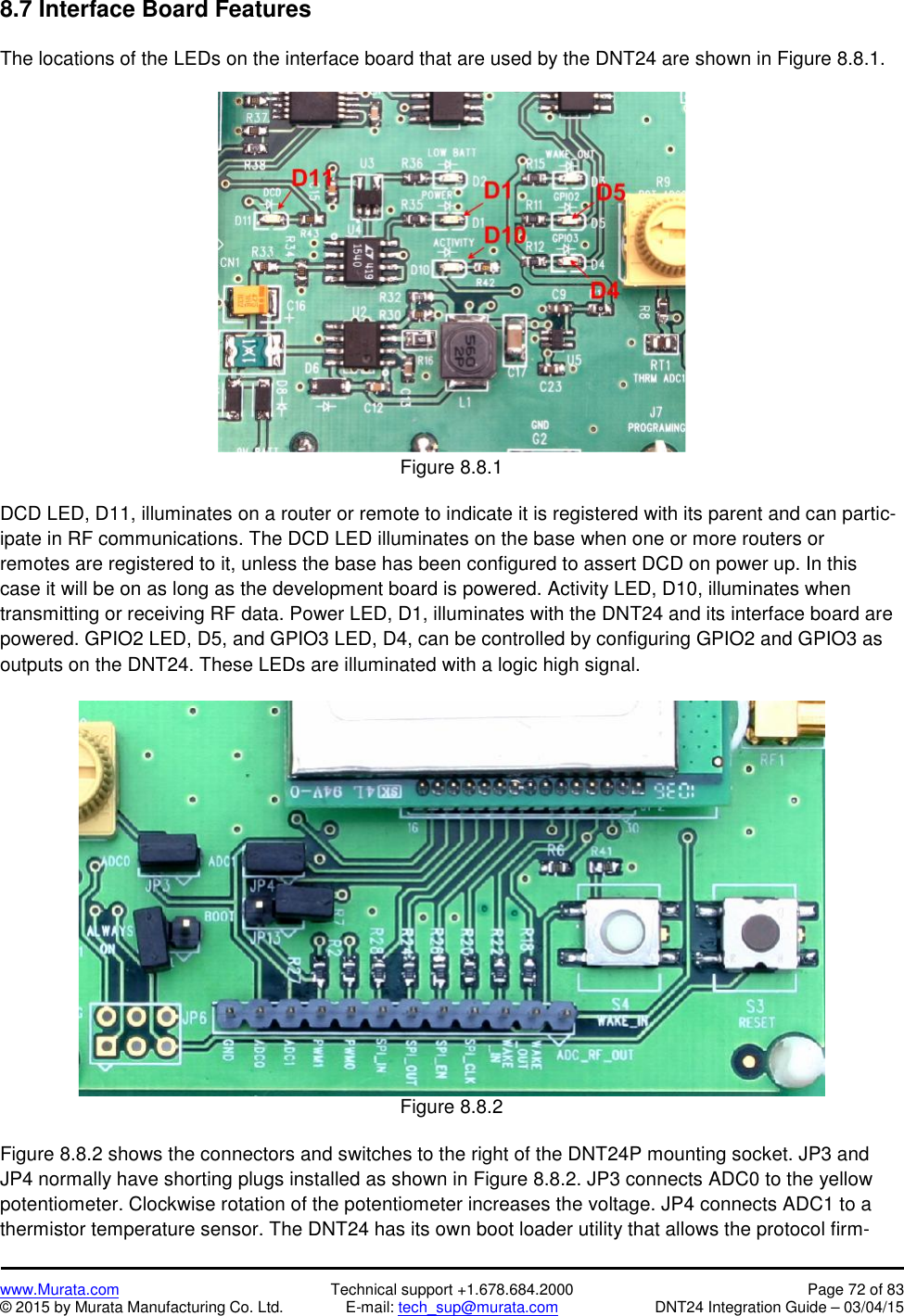
![www.Murata.com Technical support +1.678.684.2000 Page 74 of 83© 2015 by Murata Manufacturing Co. Ltd. E-mail: tech_sup@murata.com DNT24 Integration Guide – 03/04/159.0 TroubleshootingDNT24 not responding - make sure /RESET is not asserted (logic low). Make sure the host serial portsettings match the DNT24 serial port settings.Can not enter protocol mode - make sure the host data rate is correct. The DNT24 defaults to 9.6 kbps. Ifusing the EnterProtocolMode command, send the complete protocol format for this command.A remote never detects carrier (DCD) - check that the base is running, and that the remote’s System-NwkID is the same as the base, and that the ParentNwkID parameter is the same as the base, or is set to0xFF. Also make sure that the security keys are the same.Carrier is detected, but no data appears to be received - if /HOST_RTS is enabled, make sure it is as-serted (logic low) to enable character flow from the DNT24.Range is extremely limited - this is usually a sign of a poor antenna connection or the wrong antenna.Check that the antenna is firmly connected. If possible, remove any obstructions near the antenna.9.1 Diagnostic Port CommandsThe diagnostic port shares its RX and TX signal lines with the Activity and DCD indications, respectively.Consequently, the debug port feature must be enabled before being used (Bank 0xFF). The change mustbe saved and the module then needs to be reset for this to take effect. The diagnostic port is defaulted to38.4 kbps, 8N1.The diagnostic port supports the following user commands:rbr <bank> <reg> <span> - read a parameter register’s value from the module.rbw <bank> <reg> <span> <value> [<value> <value>] - write a parameter register’s valuewith a span of up to 3 bytesstat <option> - option = 0 is off, option = 1 displays DataTx/AckRx for a hopsequence in time order, and option = 2 displays any packet RX or packet error for a hopsequence in frequency order.base <0 or 1> - For a router, this determines whether the stat option displays dataassociated with its operation as a base (1) or as a remote (0).](https://usermanual.wiki/Murata-Electronics-North-America/DNT24.Users-Manual-Rev-2/User-Guide-2552810-Page-74.png)