Murata Electronics North America XDM2140 Modular 2.4GHz Transceiver User Manual
Murata Electronics North America Modular 2.4GHz Transceiver Users Manual
UserManual.wiki
>
Murata Electronics North America
>
XDM2140 User Manual
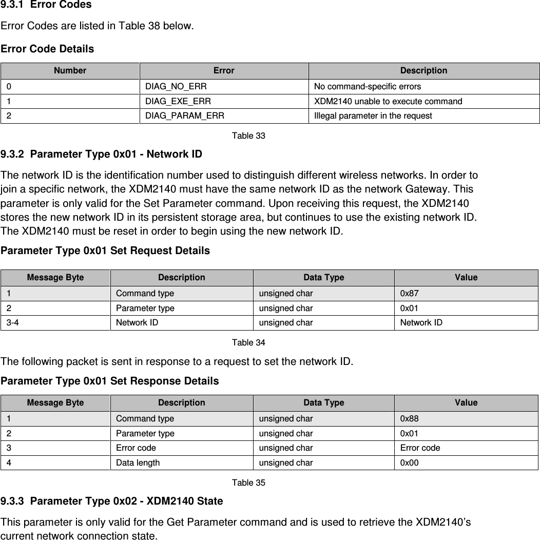
Users Manual
Navigation menu
Upload a User Manual
Namespaces
Wiki Guide
HTML
PDF
Info
Views
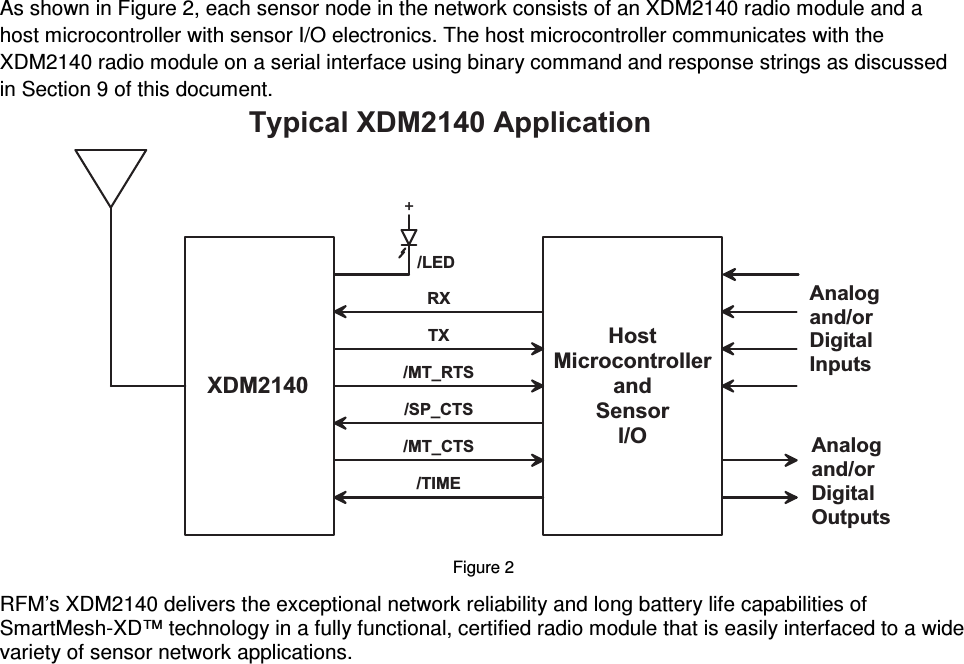
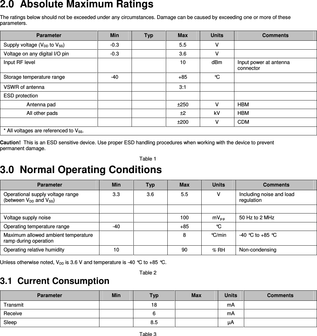
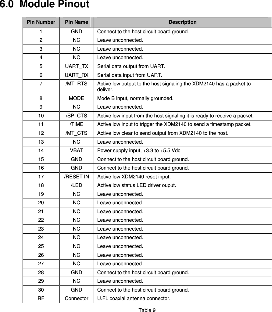
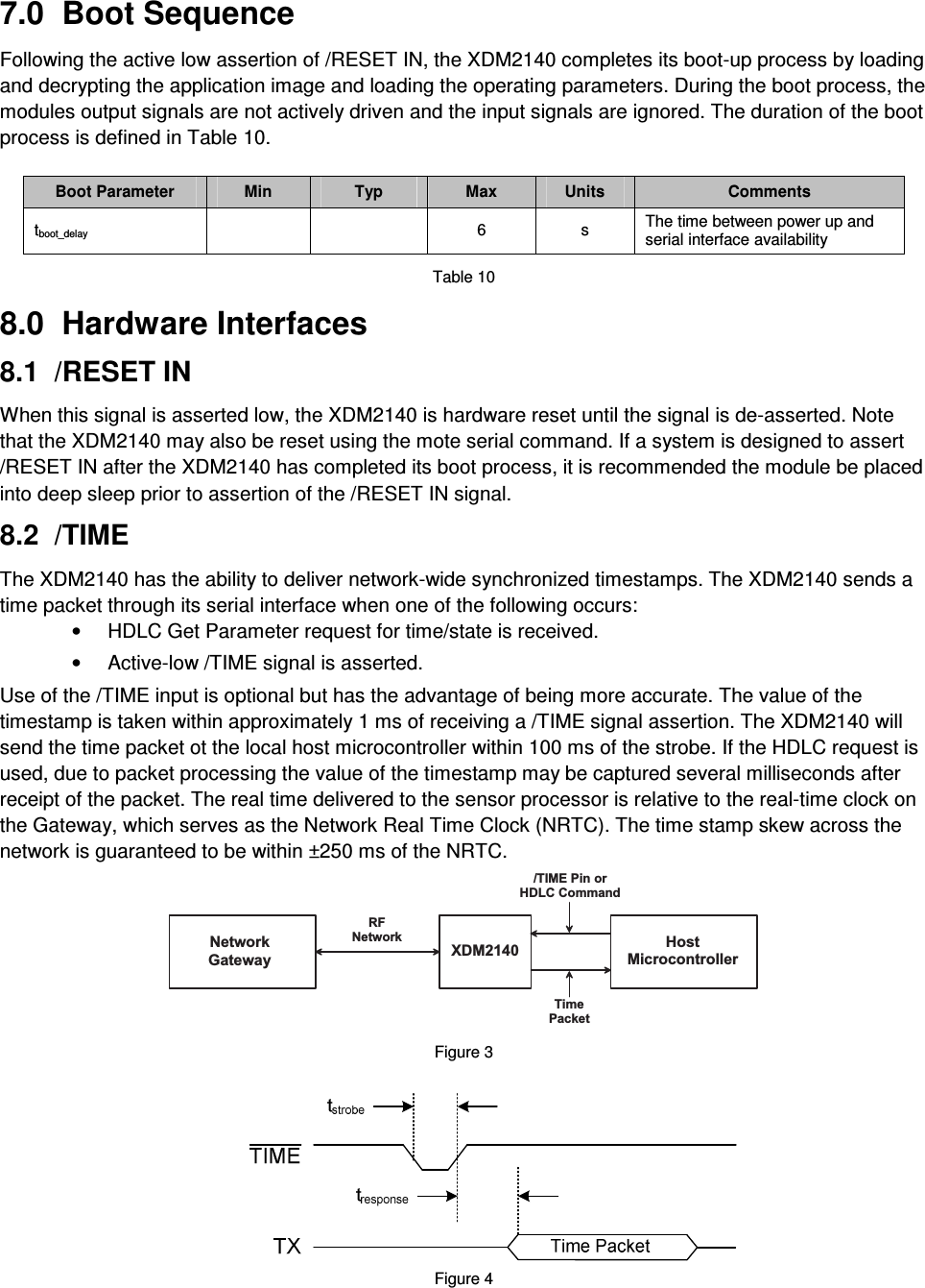
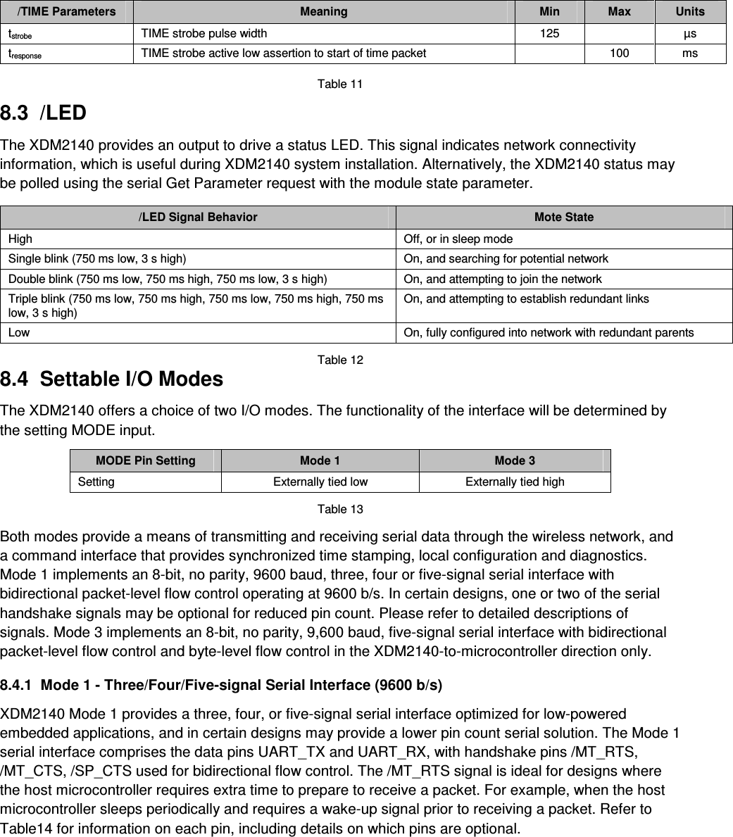
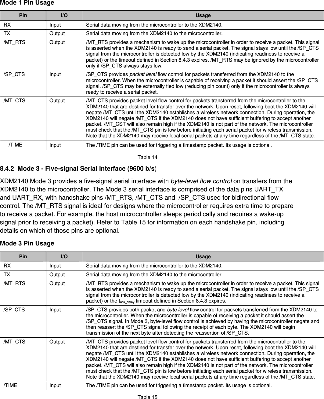
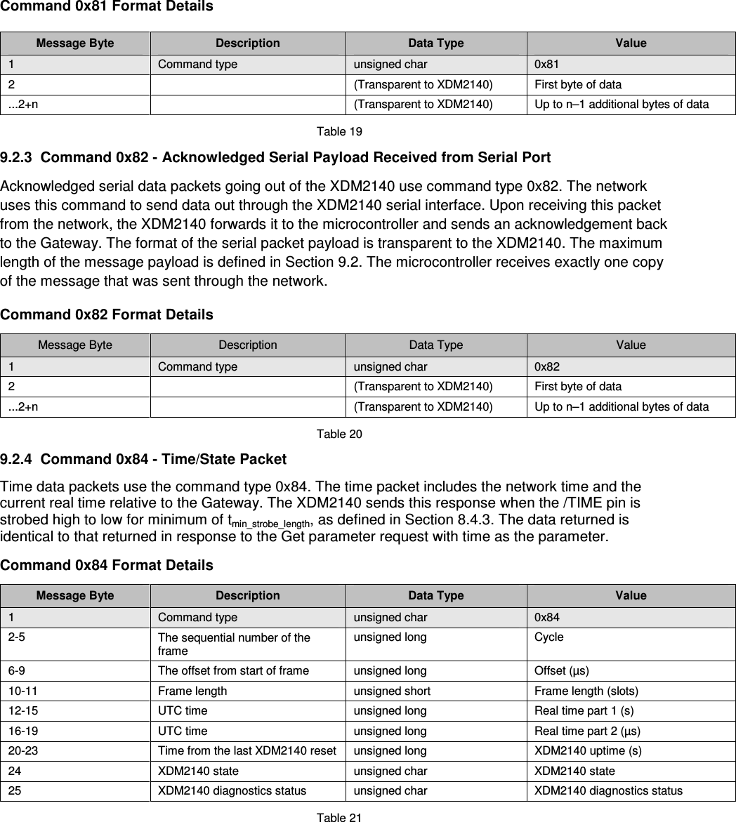
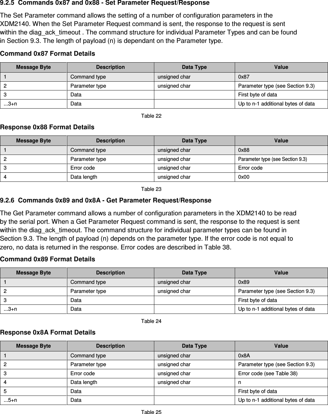
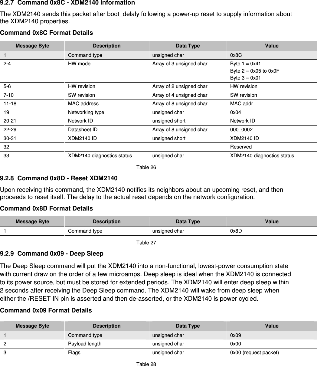
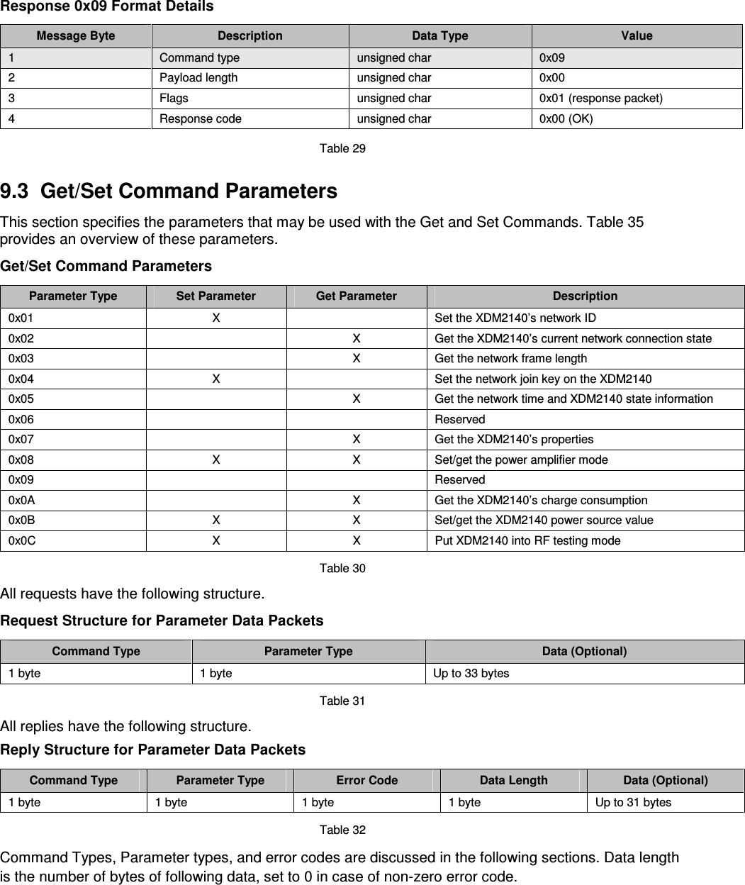
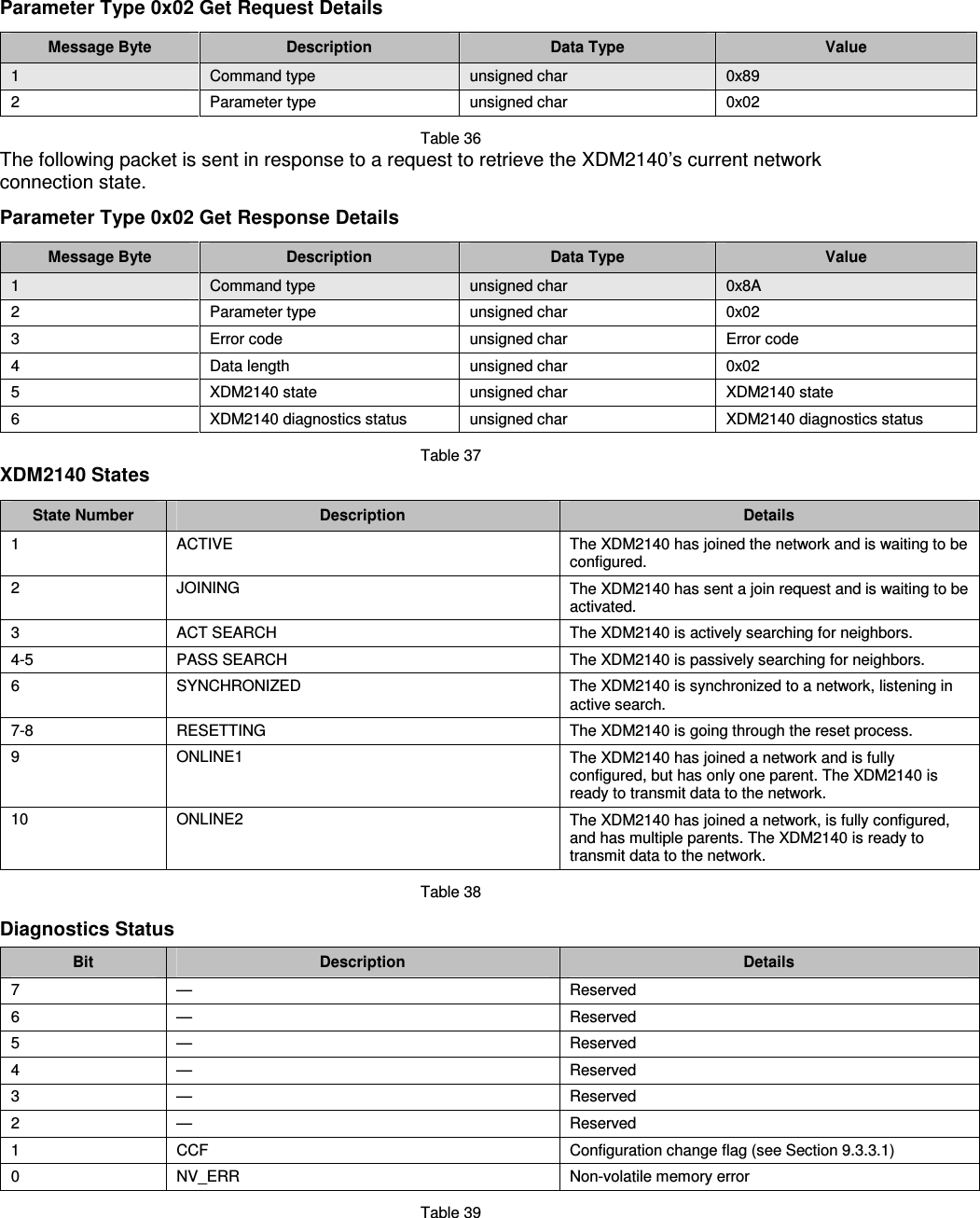
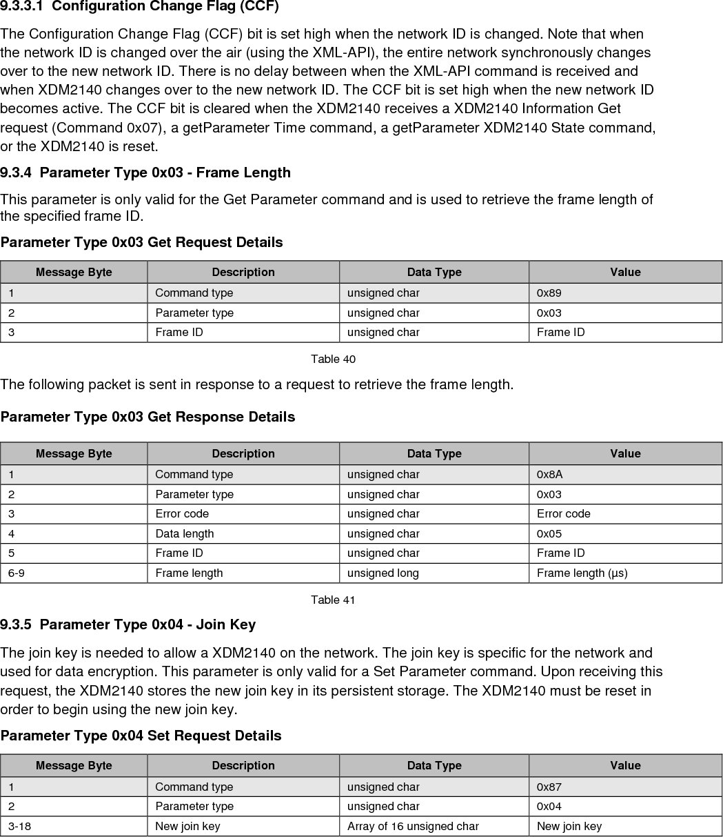
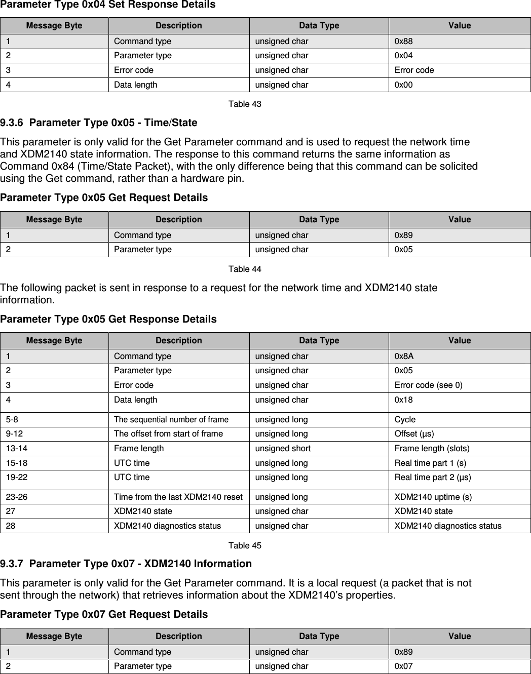
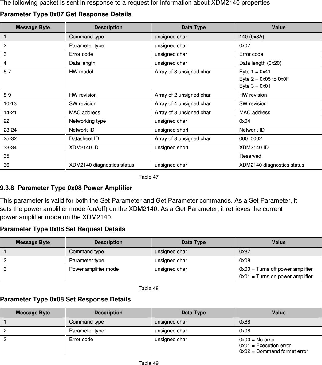
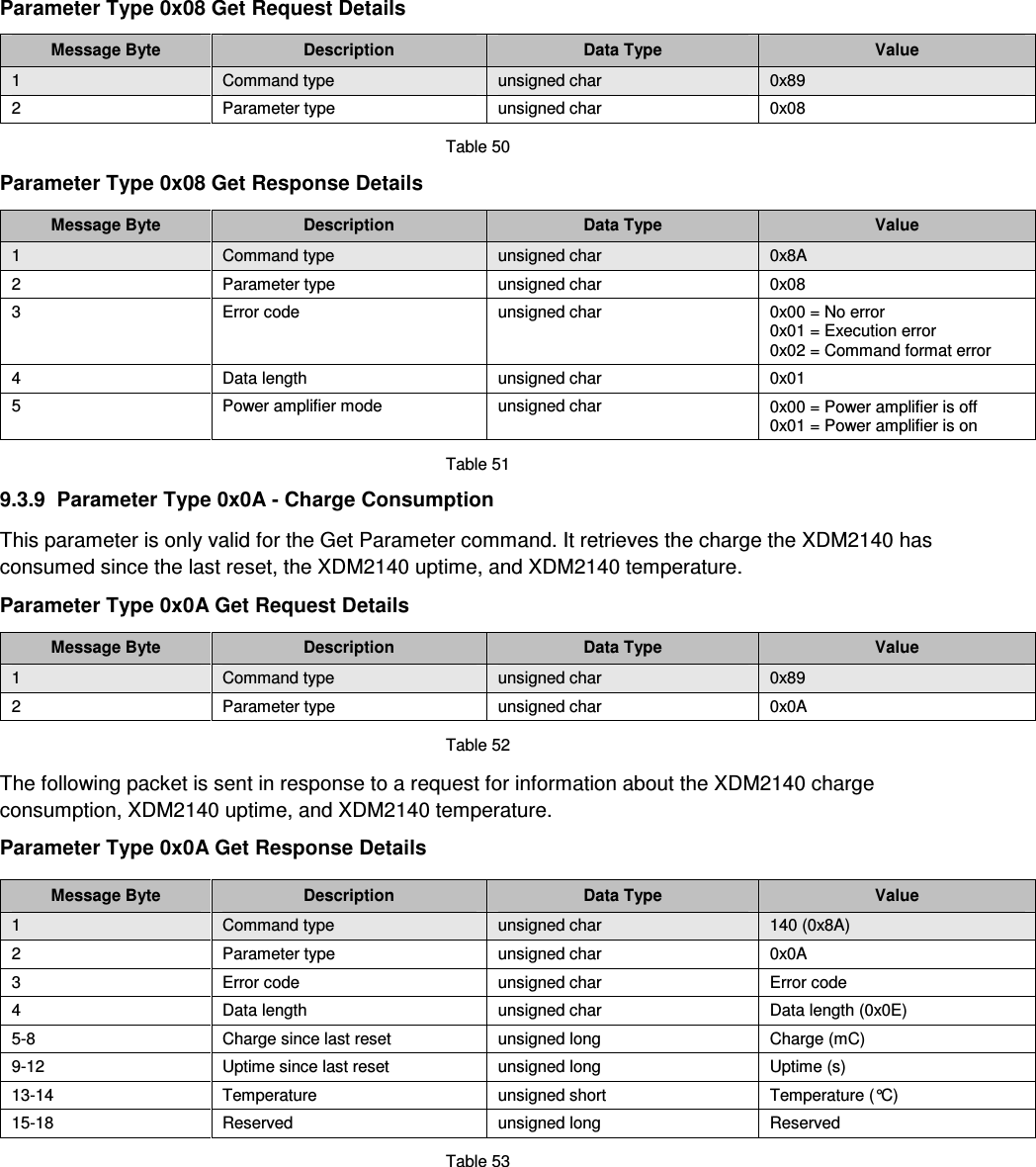
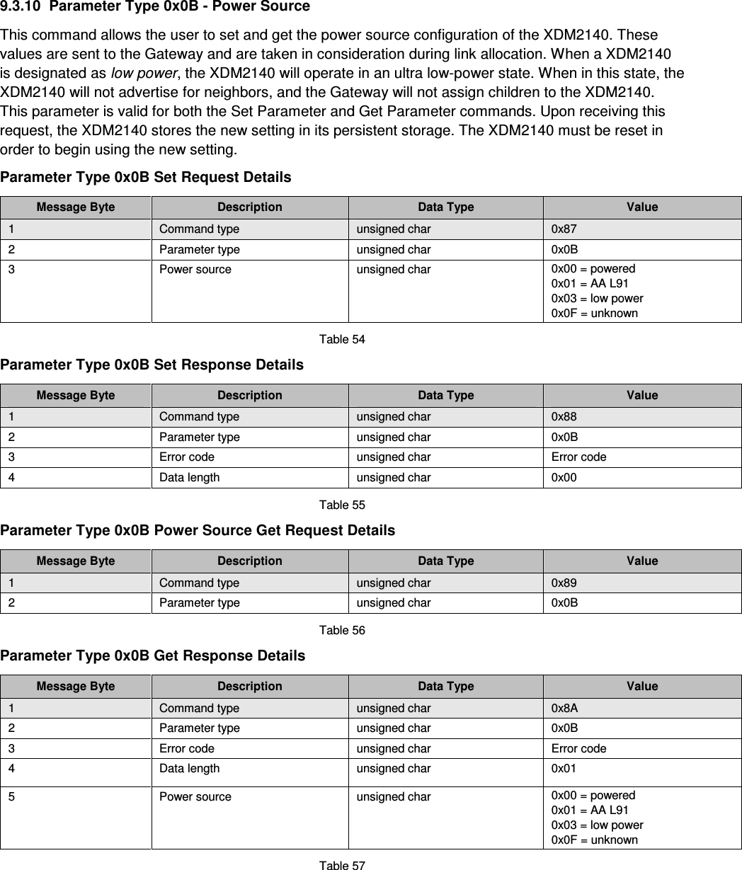
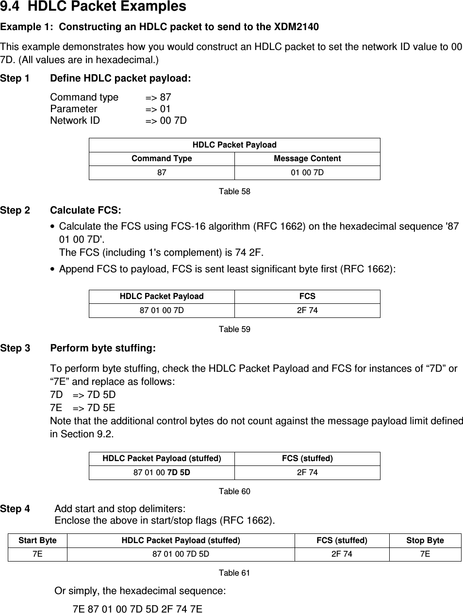
User Manual
Discussion / Help
Navigation