Muratec Automation VEHICLECMC CMC User Manual
Muratec Automation Co.,LTD CMC Users Manual
UserManual.wiki
>
Muratec Automation
>
VEHICLECMC User Manual
Users Manual
Navigation menu
Upload a User Manual
Namespaces
Wiki Guide
HTML
PDF
Info
Views
User Manual
Discussion / Help
Navigation
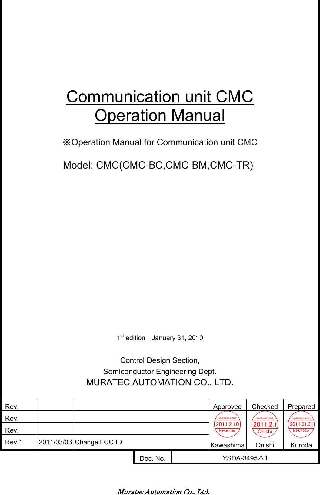

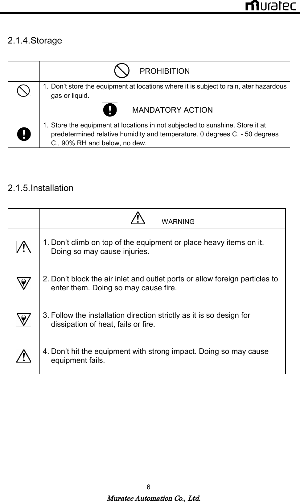
![Muratec Automation Co., Ltd.Muratec Automation Co., Ltd.Muratec Automation Co., Ltd.Muratec Automation Co., Ltd. 4 2. Safety 2.1. Alert Boxes 2.1.1. General (1) Read and understand fully this manual and attached documents before operating the products. (2) Engage specialists in electrical and mechanical works. (3) Don’t improve the product by yourselves. (4) Be sufficiently proficient with the equipment, the relevant safety knowledge and the precautions prior to using this product. In the content of this “Safety Precautions ”, items which need to be alert shall be classified into “DANGER”, “WARNING” and ”CAUTION”. 2.1.2. Definitions of DANGER, WARNING and CAUTION DANGER: An imminently hazardous situation which, if not avoided, will result in death or serious injury. WARNING: A potentially hazardous situation which, if not avoided, could result in death or serious injury. CAUTION: A potentially hazardous situation which, if not avoided, may result in minor or moderate injury. [Note 1] Medium degree of injuries or light injuries refers to injuries, e.g., burns and electric shock, which do not require hospitalization of or prolonged hospital visit by the victims. As material losses refers to expanded losses pertaining to the damage of property and equipment. [Note 2] Depending on the situation, the events described under “WARNING” may also result in severe outcome. In either case, make sure that the advice is followed. After reading, make sure this information shall be kept at places where it can always be read by users.](https://usermanual.wiki/Muratec-Automation/VEHICLECMC/User-Guide-1440587-Page-5.png)
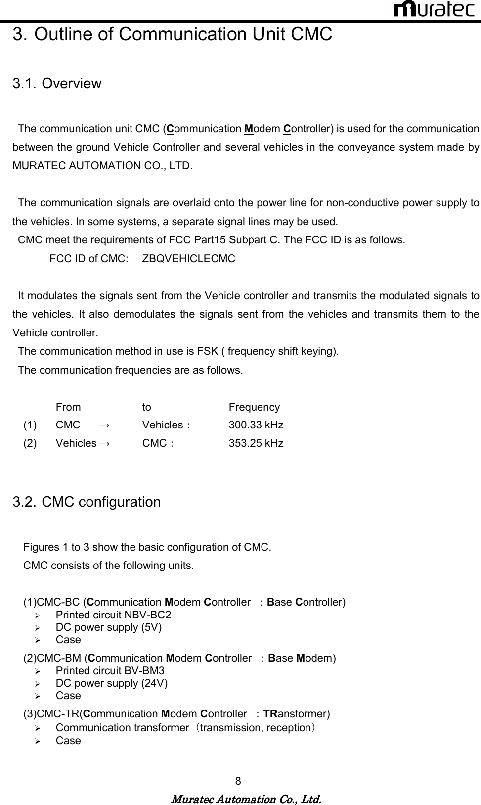
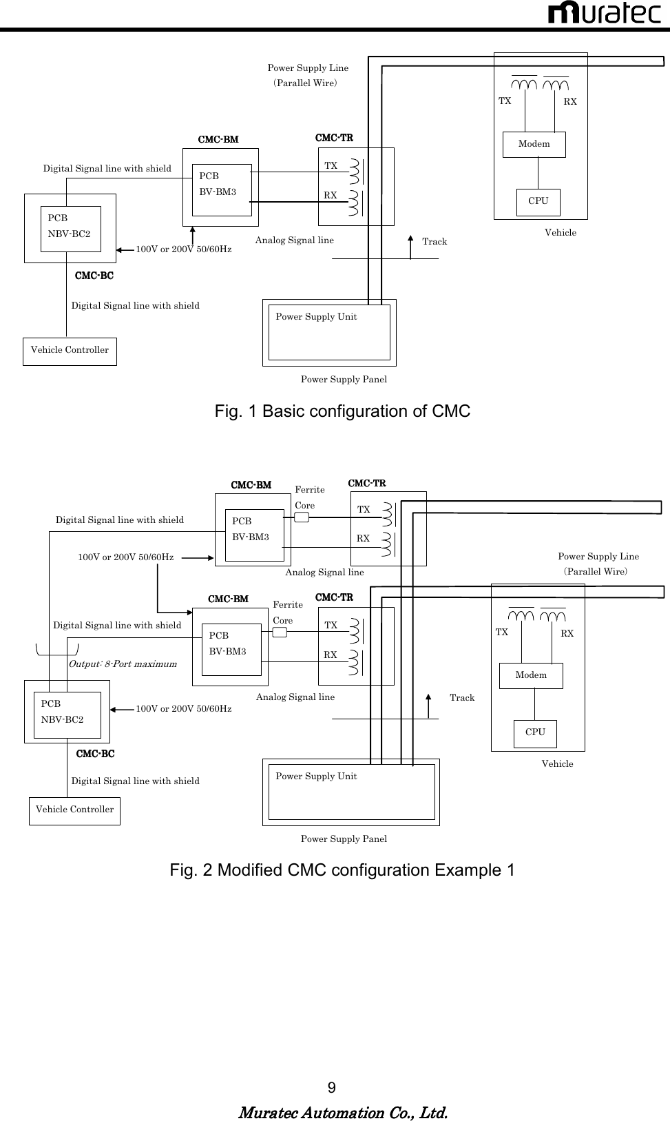
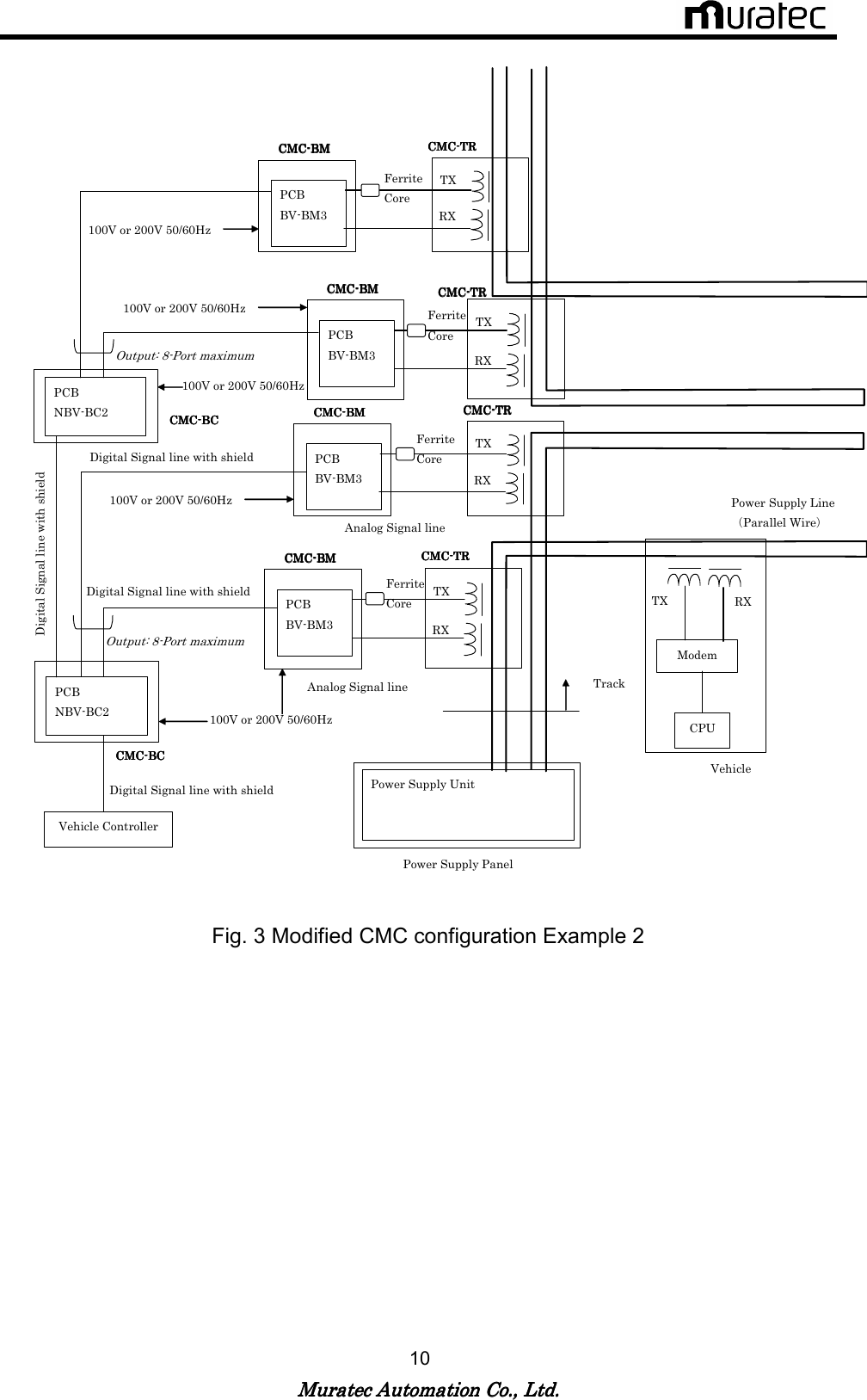
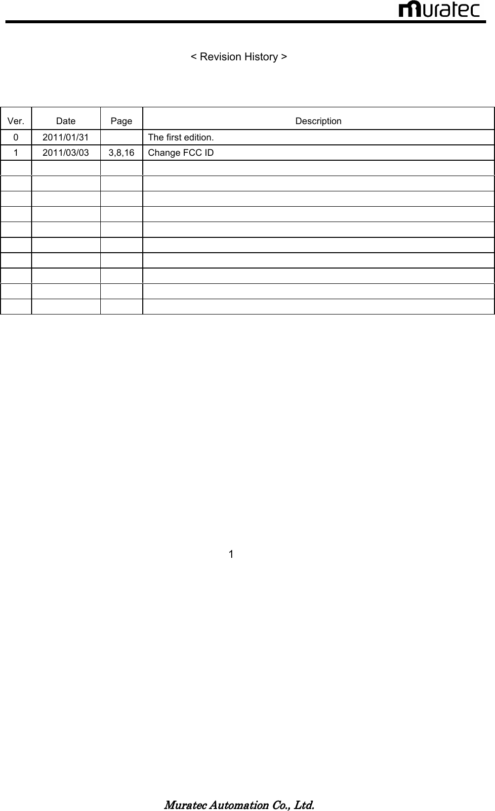
![Muratec Automation Co., Ltd.Muratec Automation Co., Ltd.Muratec Automation Co., Ltd.Muratec Automation Co., Ltd. 12 3.4. The Block Diagram of CMC Fig. 4 The block diagram of CMC CMC is a communication unit between a vehicle controller and vehicles. The communication signals modulate current signals of a power line/or signal line . The vehicle controller controls vehicle movement by transmitting and receiving this signal. [CMC-BC] Communication signals from the vehicle controller are transmitted to CMC-BC as RS232C or RS485. When communication signal is “1”, The Modulator of CMC-BC modulates 285.7 kHz FSK signal frequency. When communication signal is “0”, The Modulator of CMC-BC modulates 315.8 kHz FSK signal frequency. The modulation signal is transmitted to CMC-BM through a line driver of RS485.This modulation signals transmit to CMC-BM as RS485. [CMC-BM and CMC-TR] The modulation signal is received from CMC-BC through a line receiver of RS485. TX Amp of CMC-BM is full bridge inverter. The modulation signals are converted into a gate signal of full bridge inverter. The inverter transmits the modulation signal through resonance circuit and CMC-TR.](https://usermanual.wiki/Muratec-Automation/VEHICLECMC/User-Guide-1440587-Page-13.png)
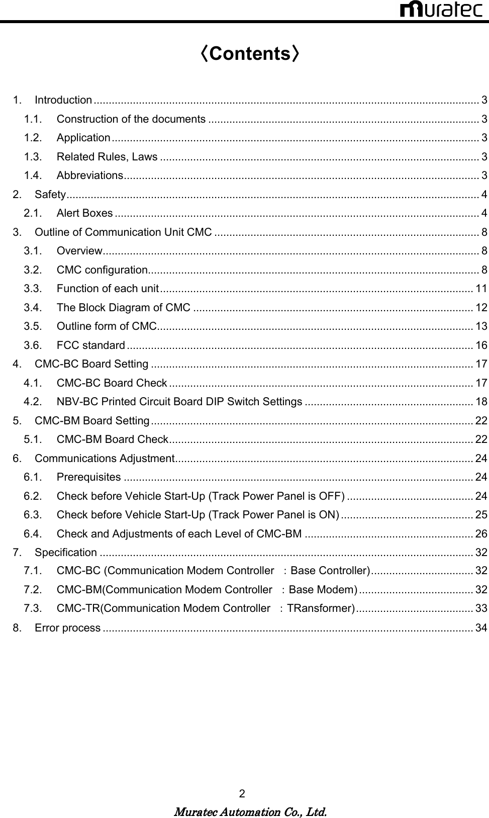
![Muratec Automation Co., Ltd.Muratec Automation Co., Ltd.Muratec Automation Co., Ltd.Muratec Automation Co., Ltd. 16 3.6. FCC standard The transmission assembly in the communication unit CMC meets FCC Part15 Subpart C as the intentional radiator. FCC ID of CMC: ZBQVEHICLECMC FCC WARNING Changes or modifications not expressly approved by the party responsible for compliance could void the user’s authority to operate the equipment. - Properly shielded and grounded cables and connectors must be used for connection to vehicle controller and CMC-BC in order to meet FCC emission limits. - Properly shielded and grounded cables and connectors must be used for connection to CMC-BM and CMC-BC in order to meet FCC emission limits. - TX transformer of CMC-TR with ferrite core must be used for RF interference suppression. Note: This equipment has been tested and found to comply with the limits for a Class A digital device, pursuant to part 15 of the FCC Rules. These limits are designed to provide reasonable protection against harmful interference when the equipment is operated in a commercial environment. This equipment generates, uses, and can radiate radio frequency energy and, if not installed and used in accordance with the instruction manual, may cause harmful interference to radio communications. Operation of this equipment in a residential area is likely to cause harmful interference in which case the user will be required to correct the interference at his own expense. [Note.1] The FCC certificate position may vary because different case materials and shapes are adopted for different customers.](https://usermanual.wiki/Muratec-Automation/VEHICLECMC/User-Guide-1440587-Page-17.png)
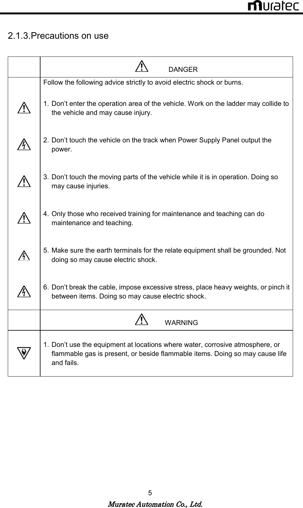
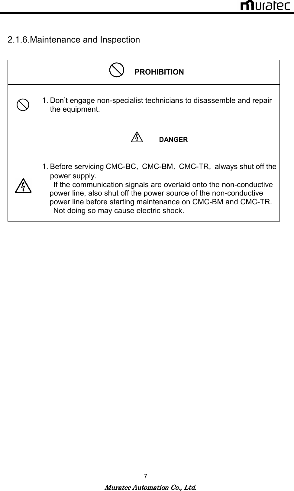
![Muratec Automation Co., Ltd.Muratec Automation Co., Ltd.Muratec Automation Co., Ltd.Muratec Automation Co., Ltd. 34 8. Error process [Note.1] Before servicing CMC-BC,CMC-BM,CMC-TR,always shut off the power supply. [Note.2] If the communication signals are overlaid onto the non-conductive power line, also shut off the power source of the non-conductive power line before starting maintenance on CMC-BM and CMC-TR. <Communication error trouble shooting> Vehicle Controller issues a communication error Is Vehicle Controller sending communication signals? Check the settings for Vehicle Controller. Are the power indicator lights of CMC-BC and CMC-BM illuminated? Is the power supply of 200V AC 1φor 100V AC 1φ50/60Hz connected? Is the input fuse burnt? Replace the fuse. Turn the power supply OFF. Is the input resistance of the DC power almost 0 ohm? Replace the DC power supply. Is the power LED of the print circuit NBV-BC illuminated? Is the power LED of the print circuit BV-BM2 illuminated? Replace the print circuit board Is the connection between CMC-BM and CMC-TR normal? Restore connection. END](https://usermanual.wiki/Muratec-Automation/VEHICLECMC/User-Guide-1440587-Page-35.png)