ND Information Technology System PS400 Mobile payment terminal with GSM/GPRS and RFID reader User Manual SAND OS operation manual
Shanghai SAND Information Technology System Co., Ltd Mobile payment terminal with GSM/GPRS and RFID reader SAND OS operation manual
Contents
- 1. User manual
- 2. Operation manual
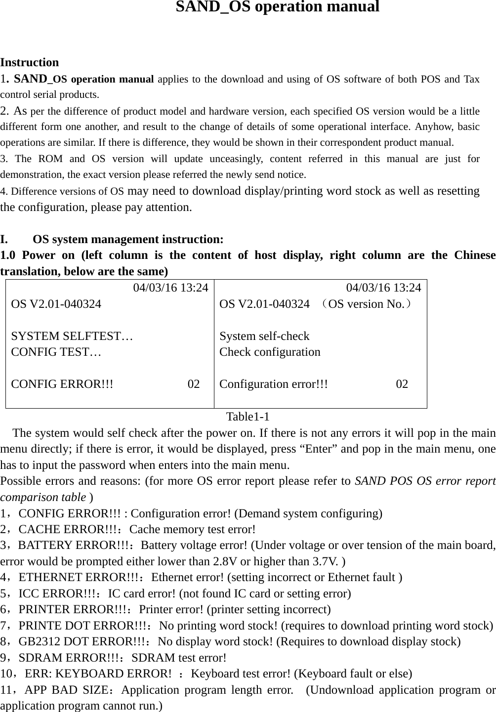
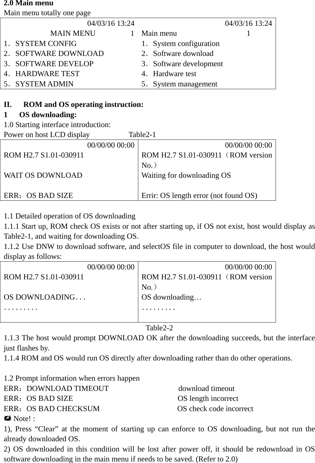
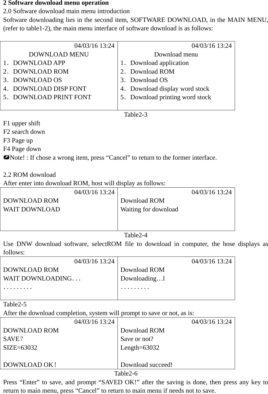
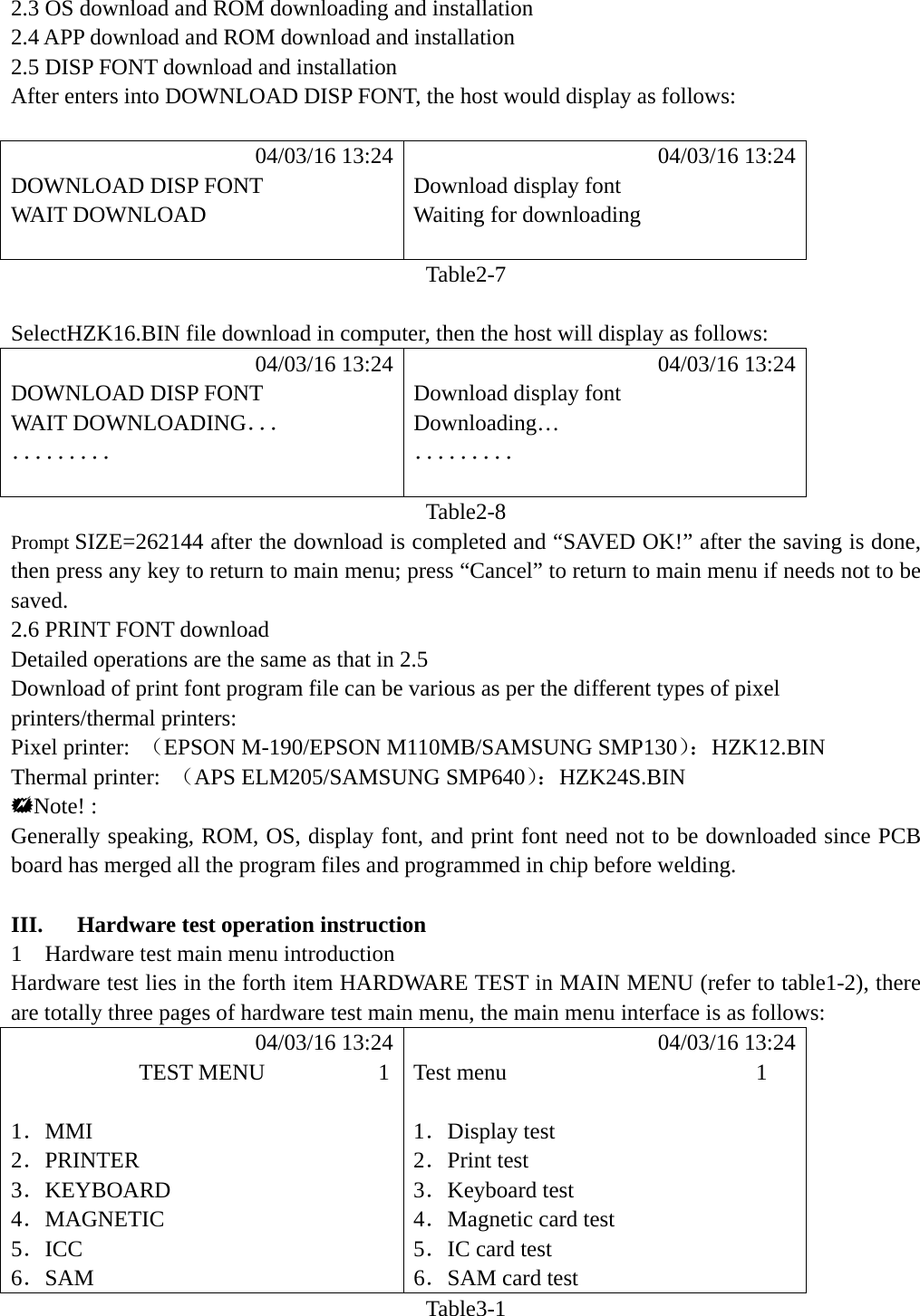
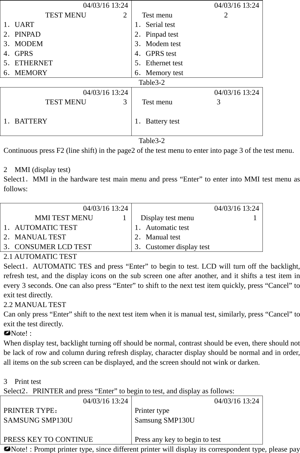
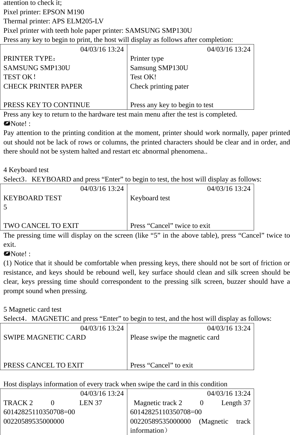
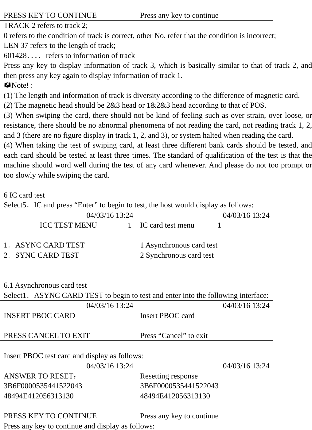
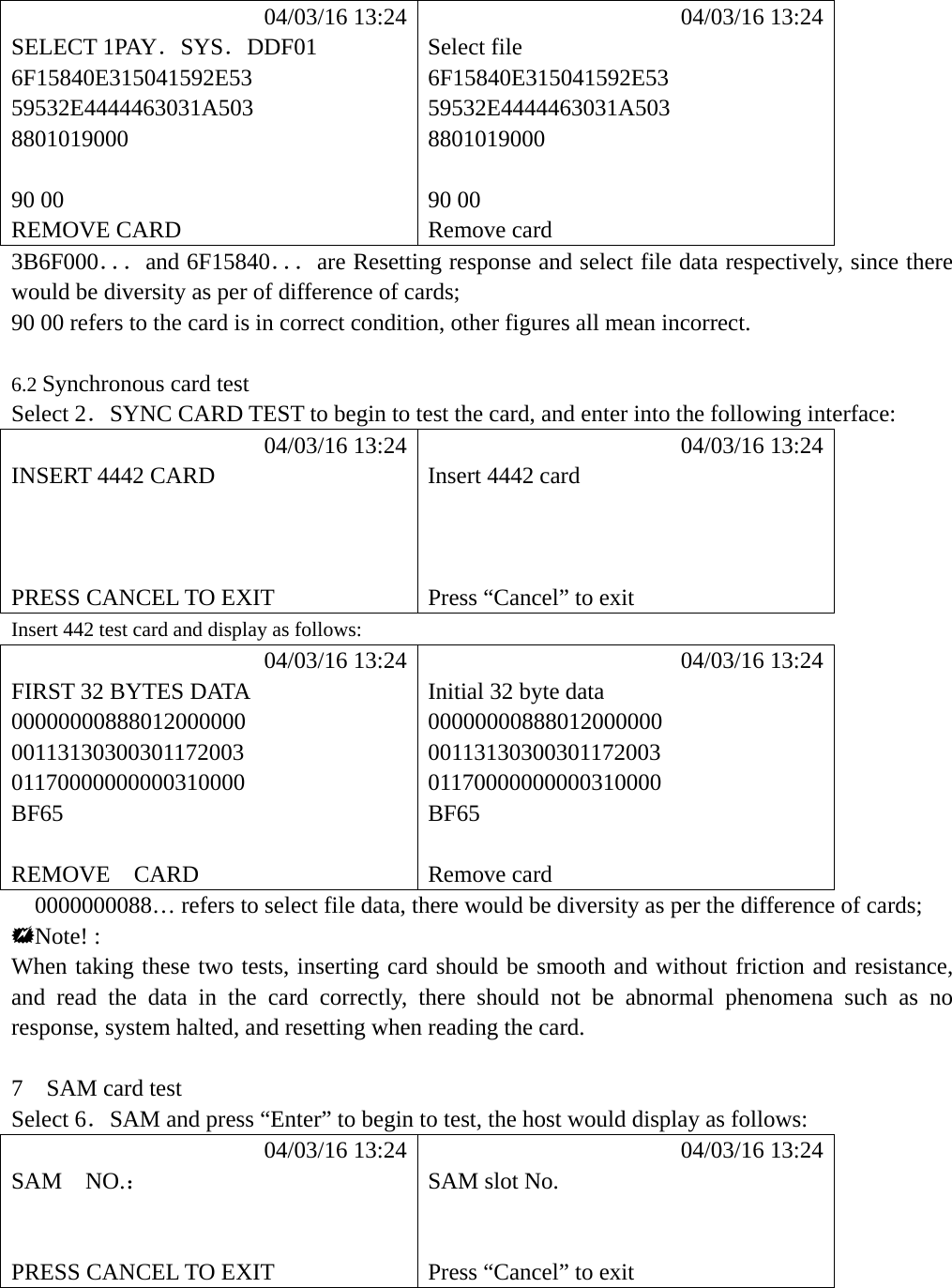
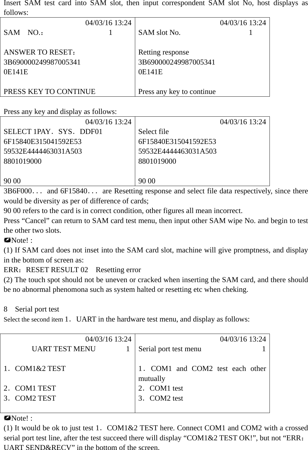
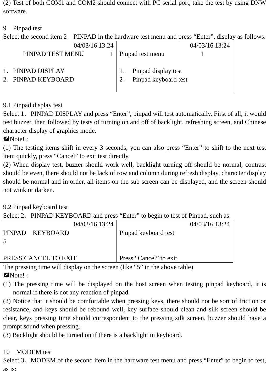
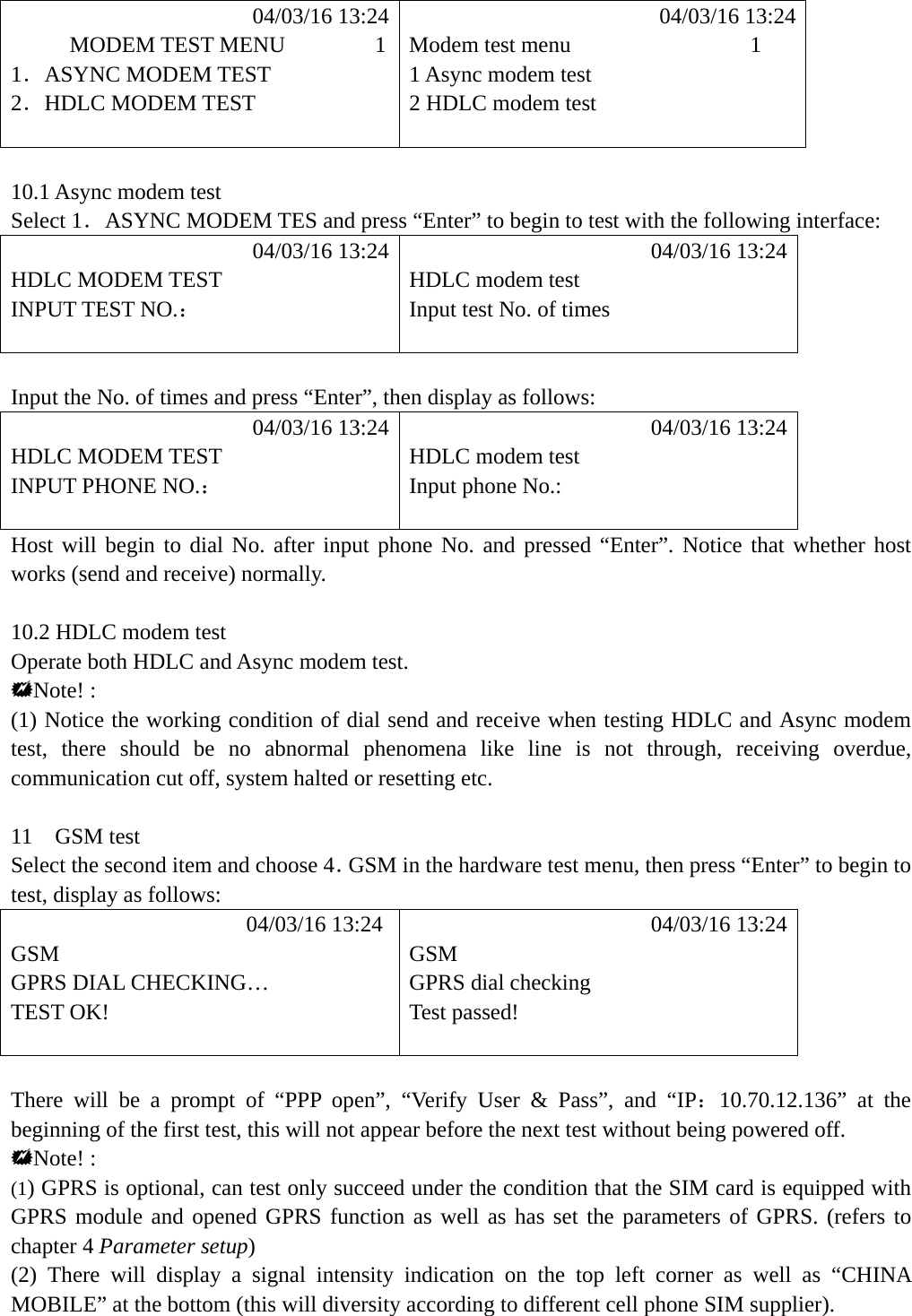
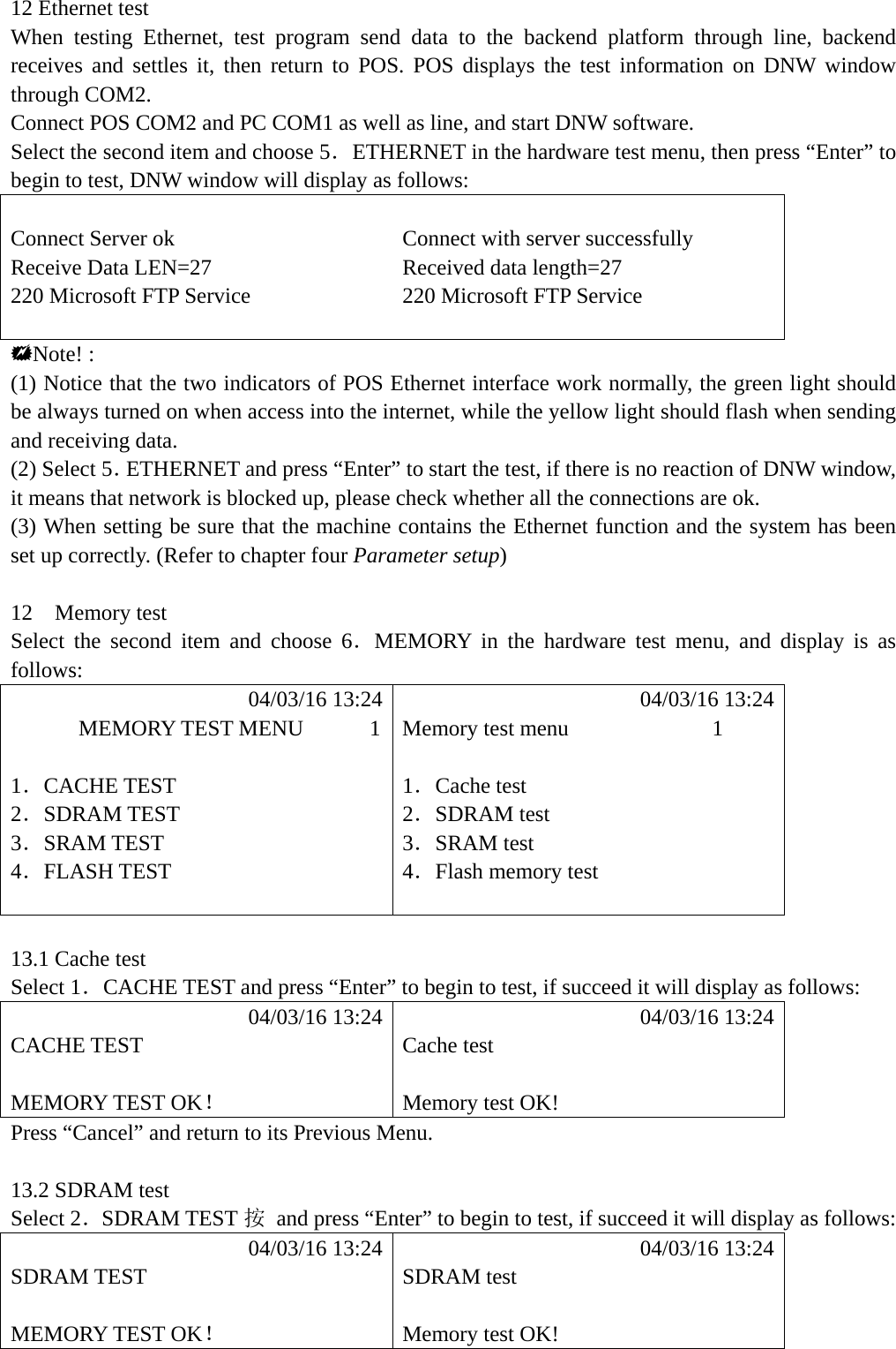
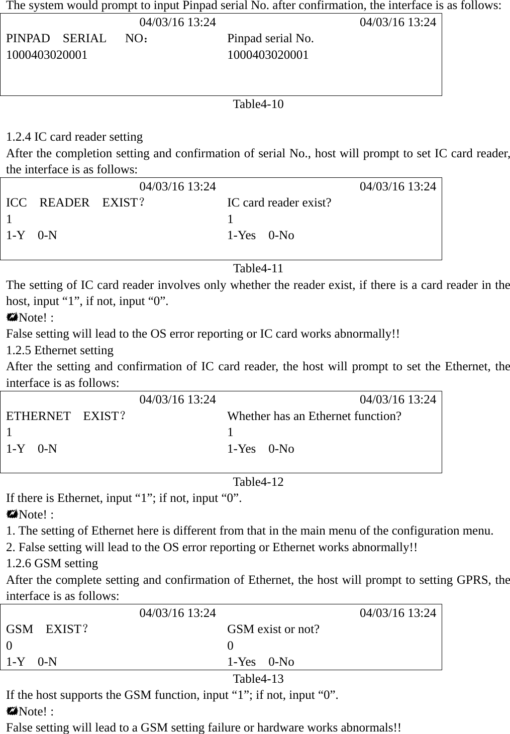
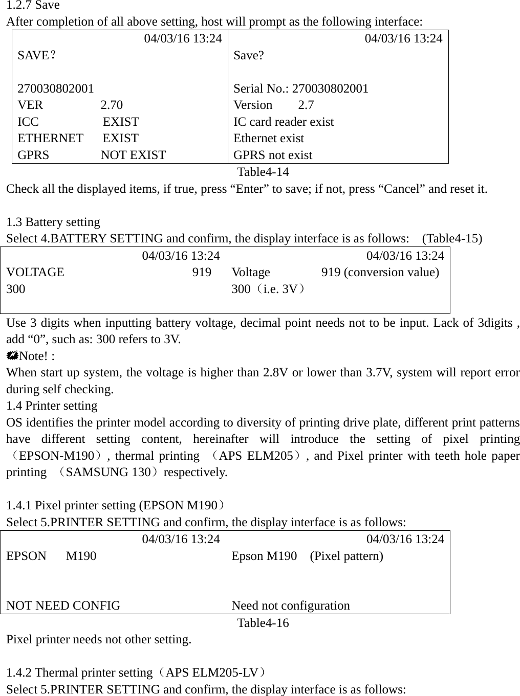
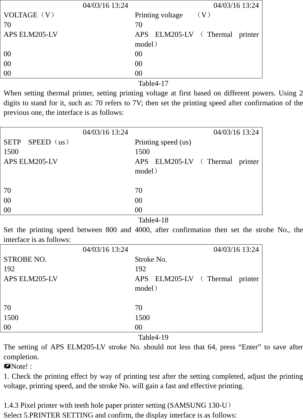
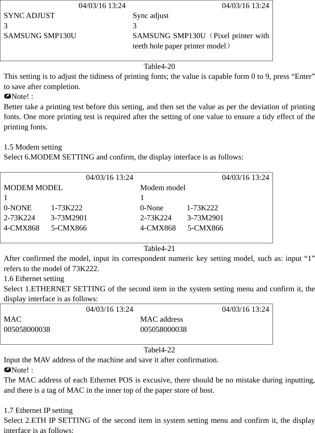
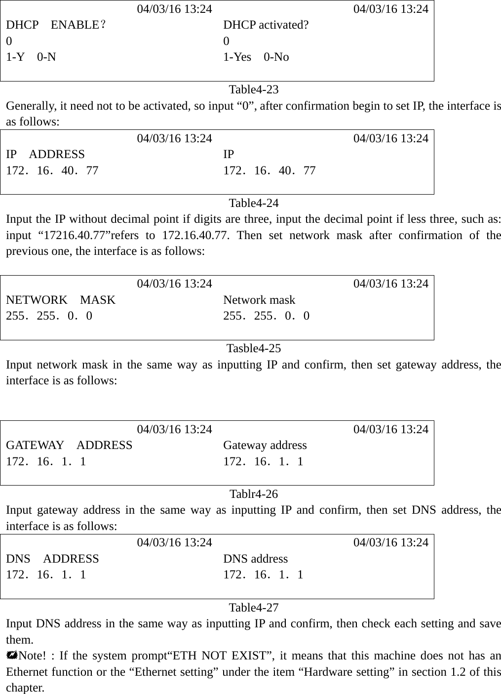
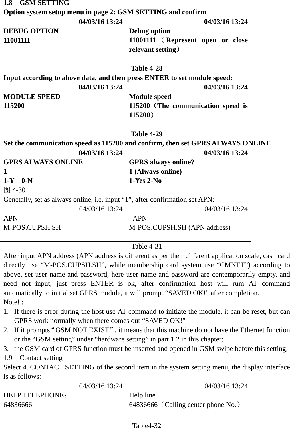
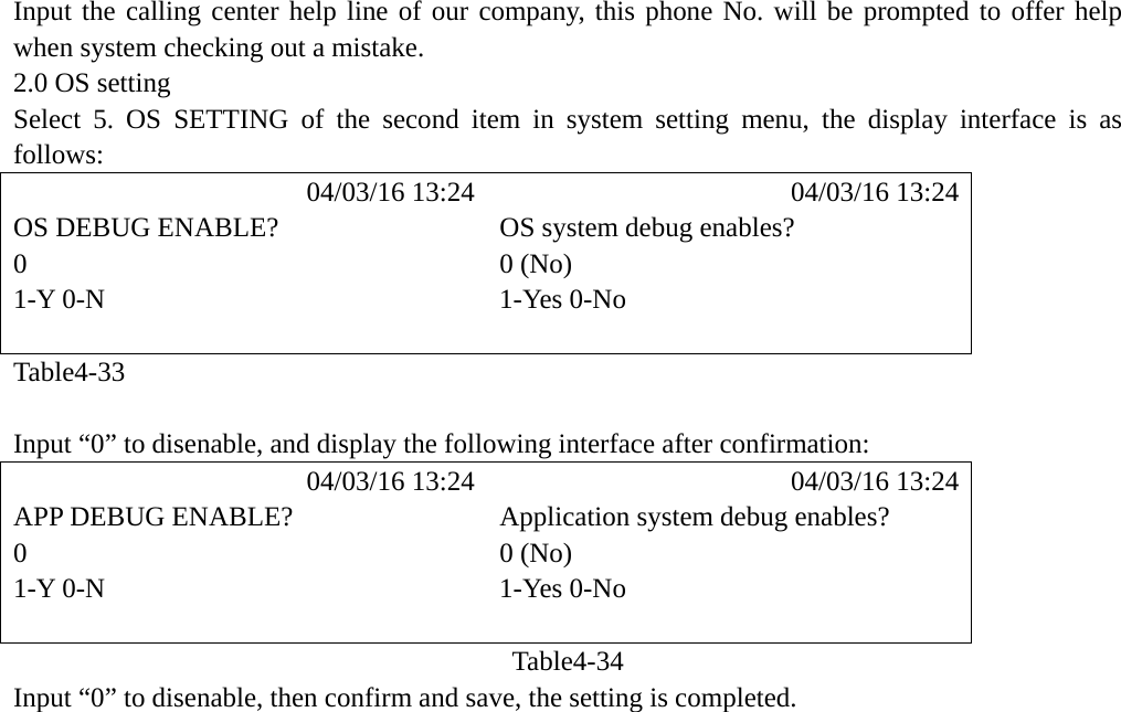
Operation manual