NEC of America 58155 NEC NLite E 155 MB 5.8 GHz Digital Microwave Radio User Manual Part 4
NEC Corporation of America NEC NLite E 155 MB 5.8 GHz Digital Microwave Radio Part 4
Contents
- 1. User Manual Part 1
- 2. User Manual Part 2
- 3. User Manual Part 3
- 4. User Manual Part 4
- 5. User Manual Part 5
User Manual Part 4
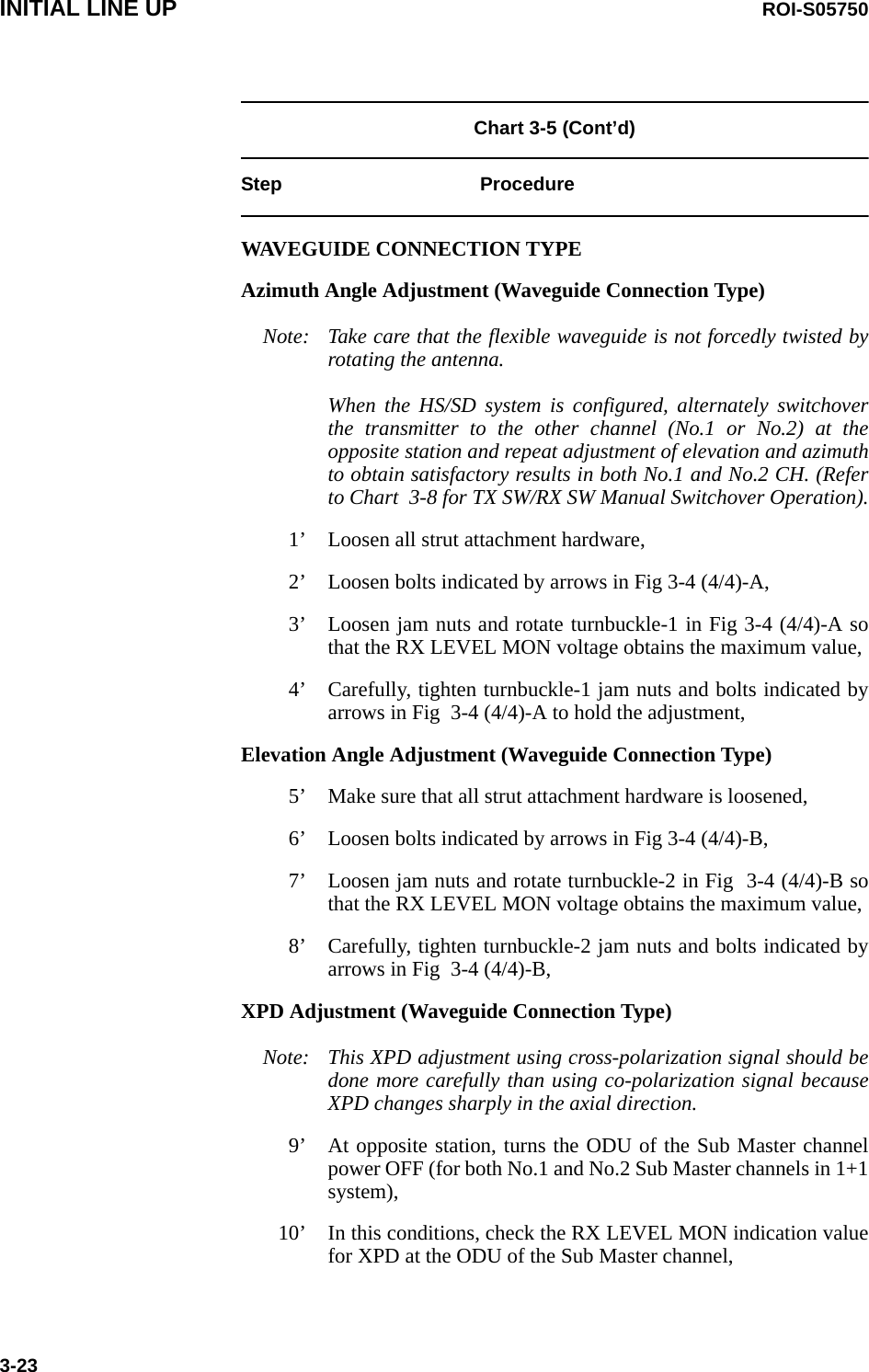
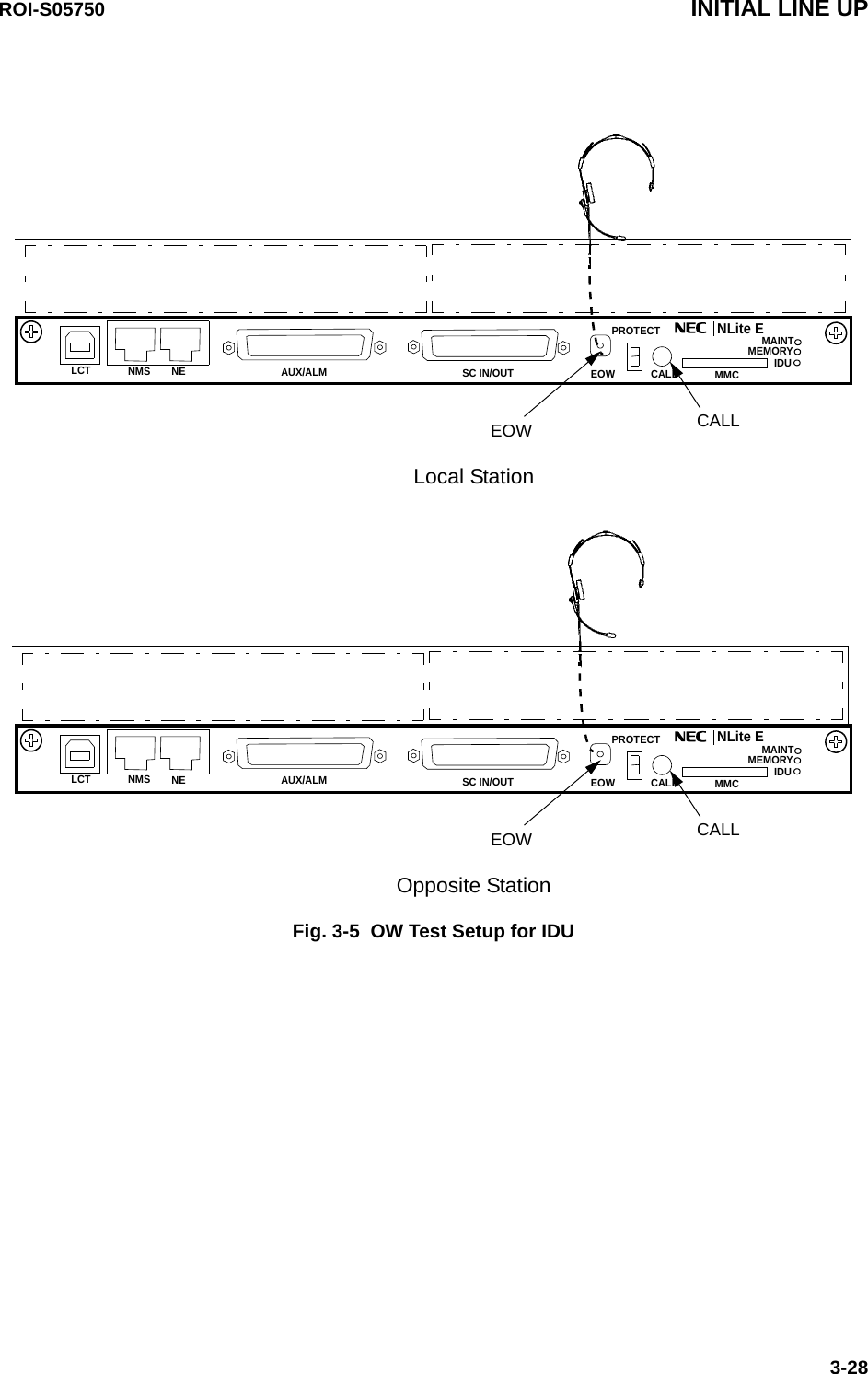
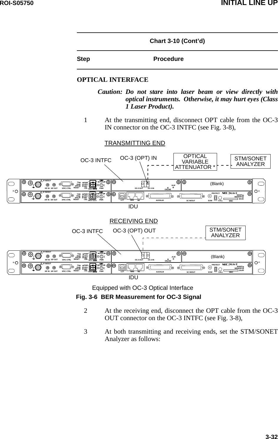
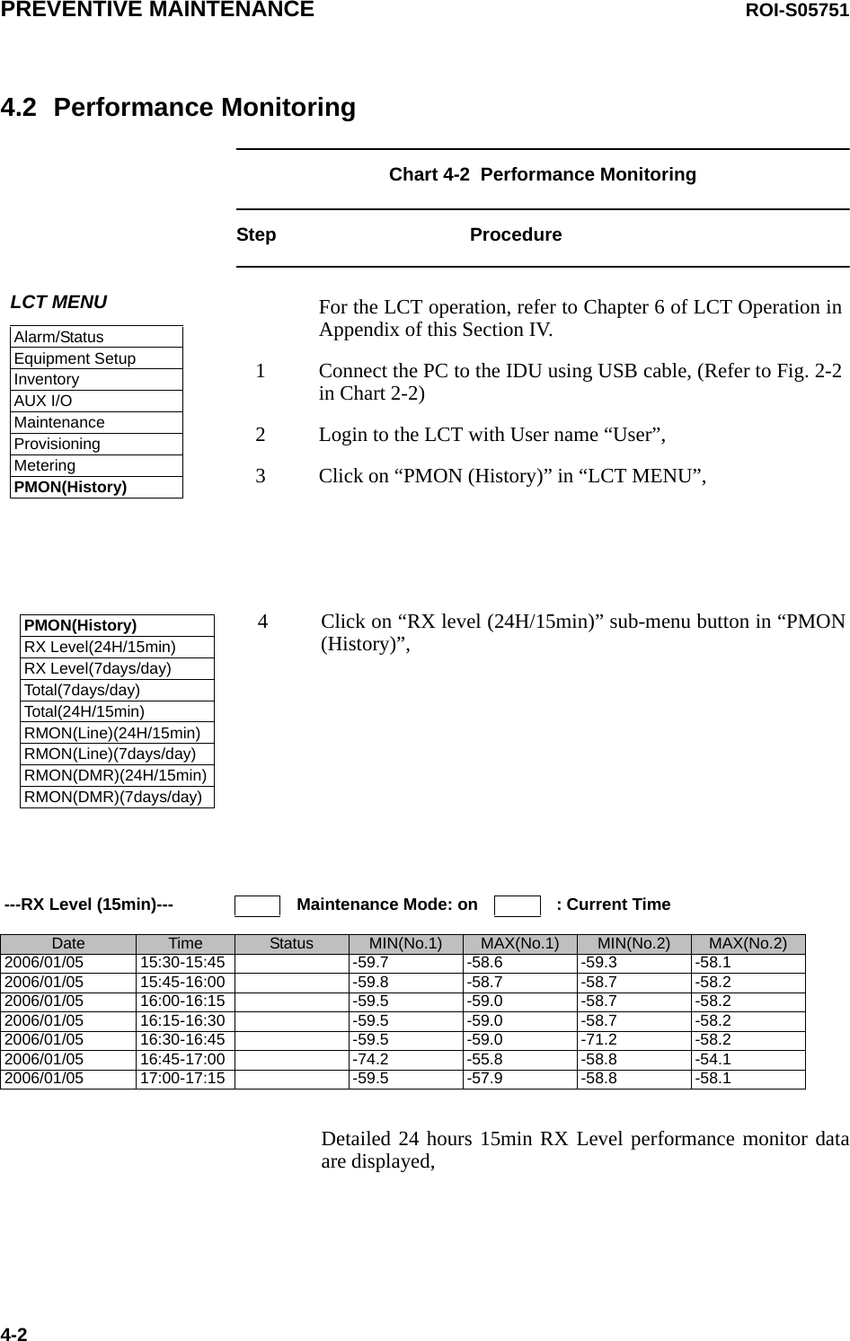
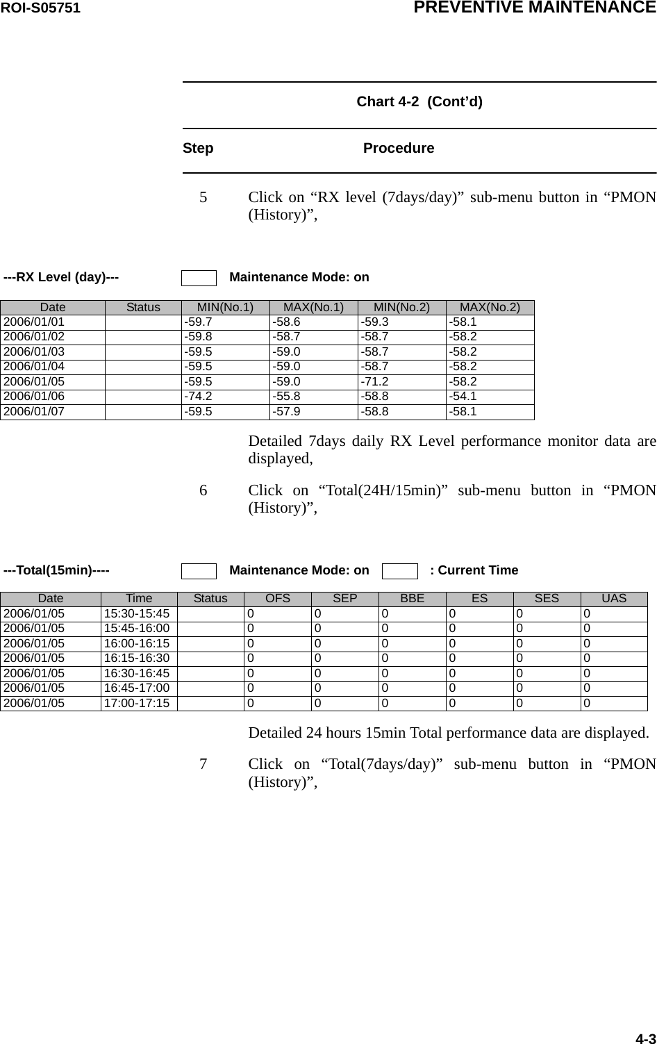
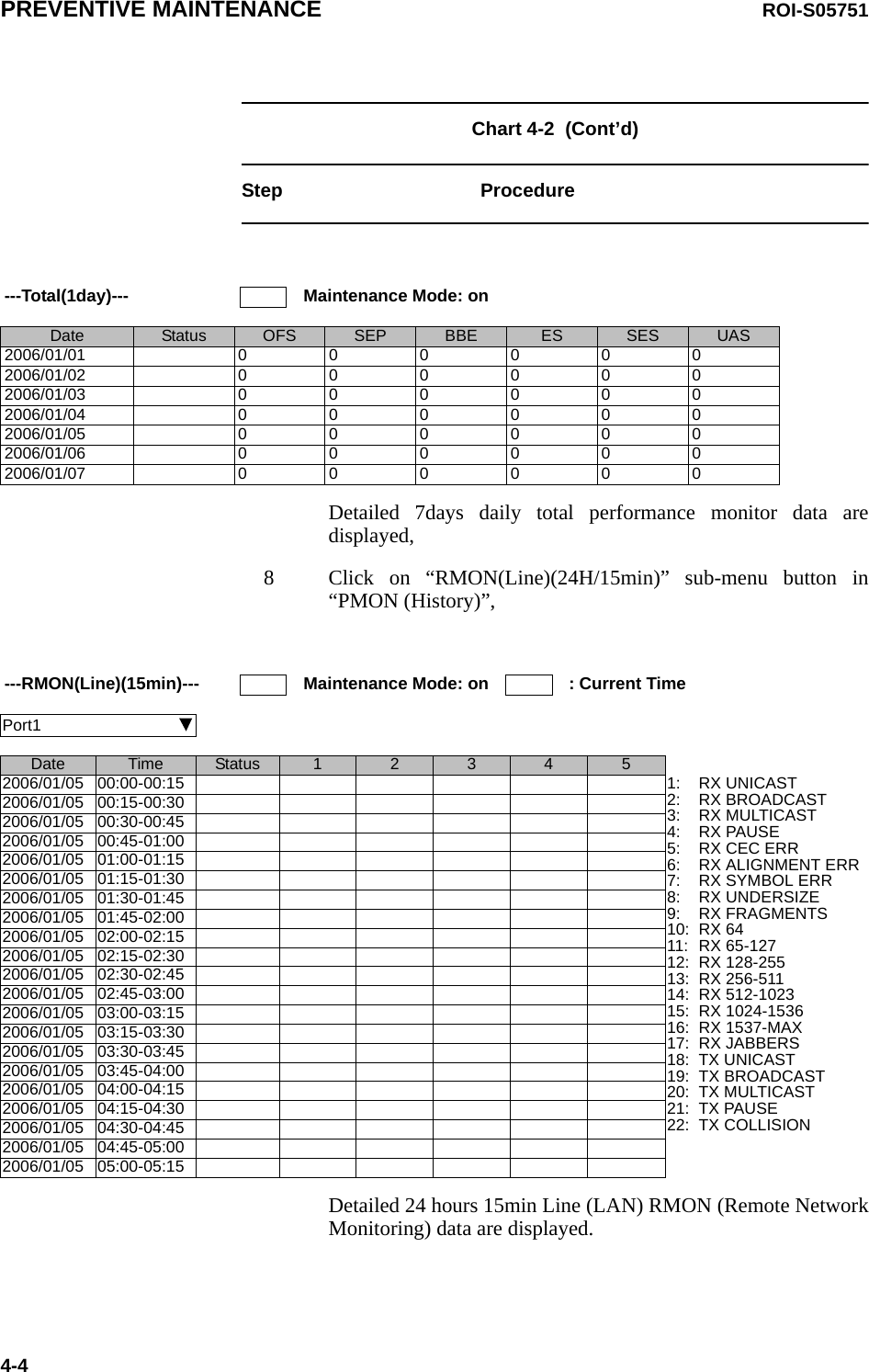
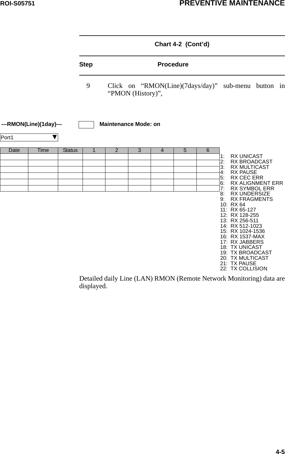
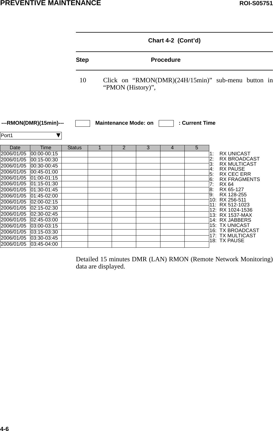
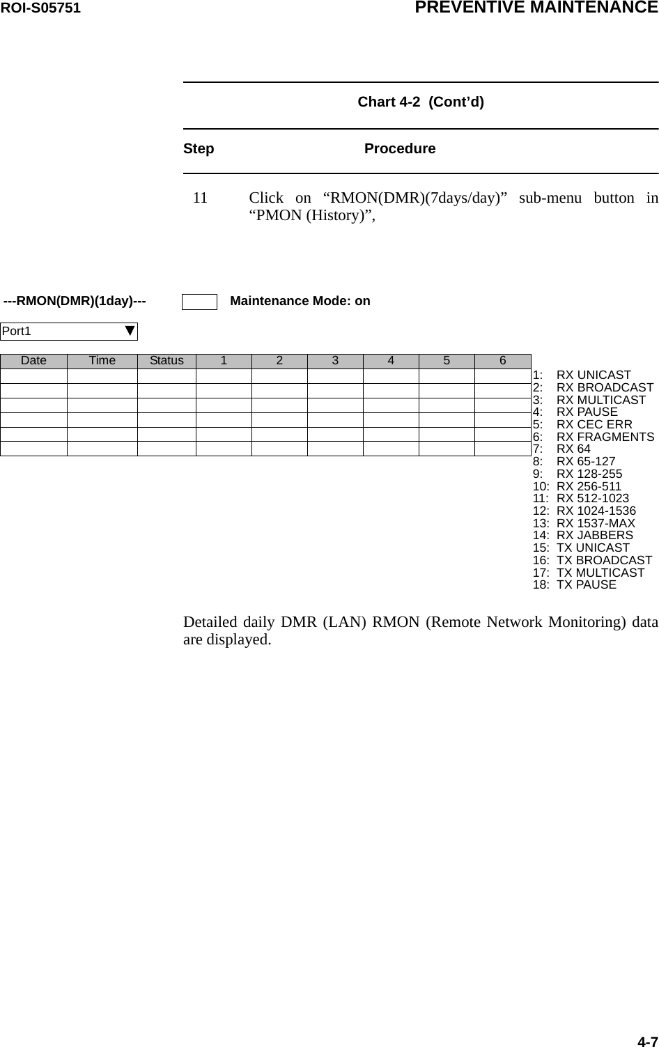
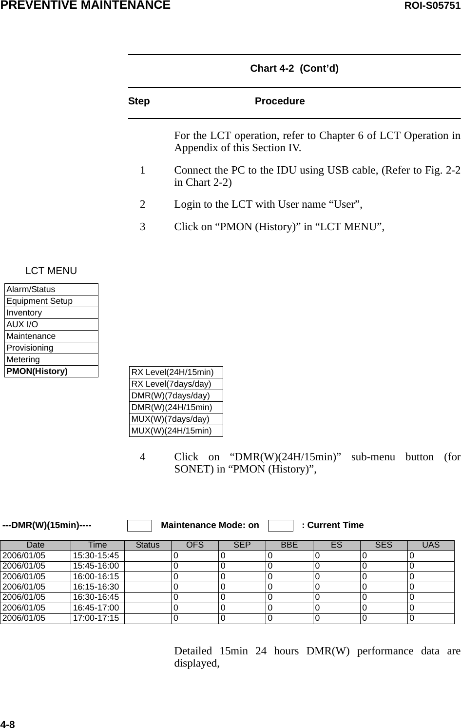
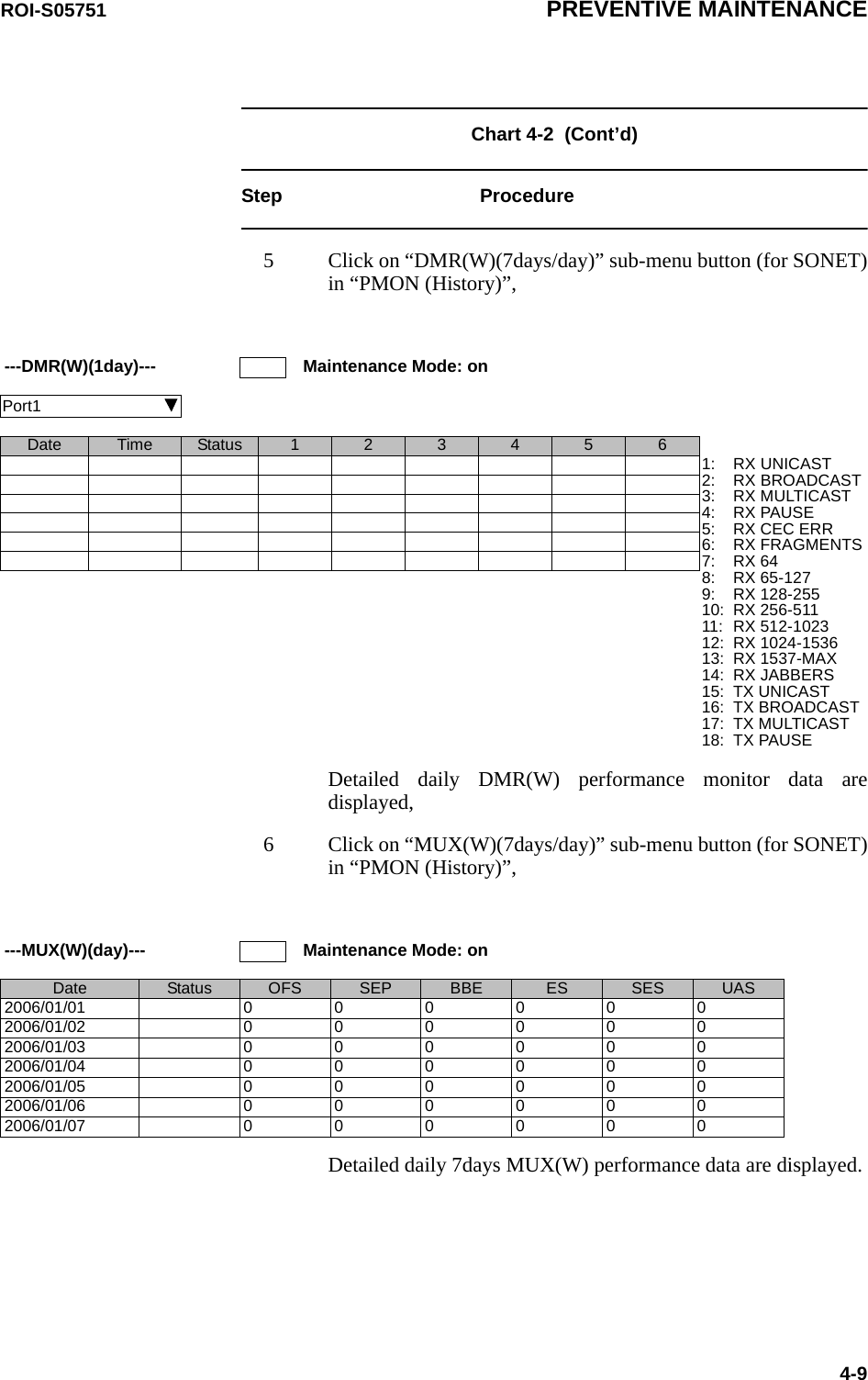
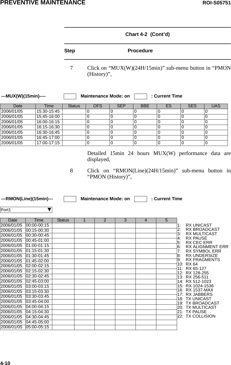
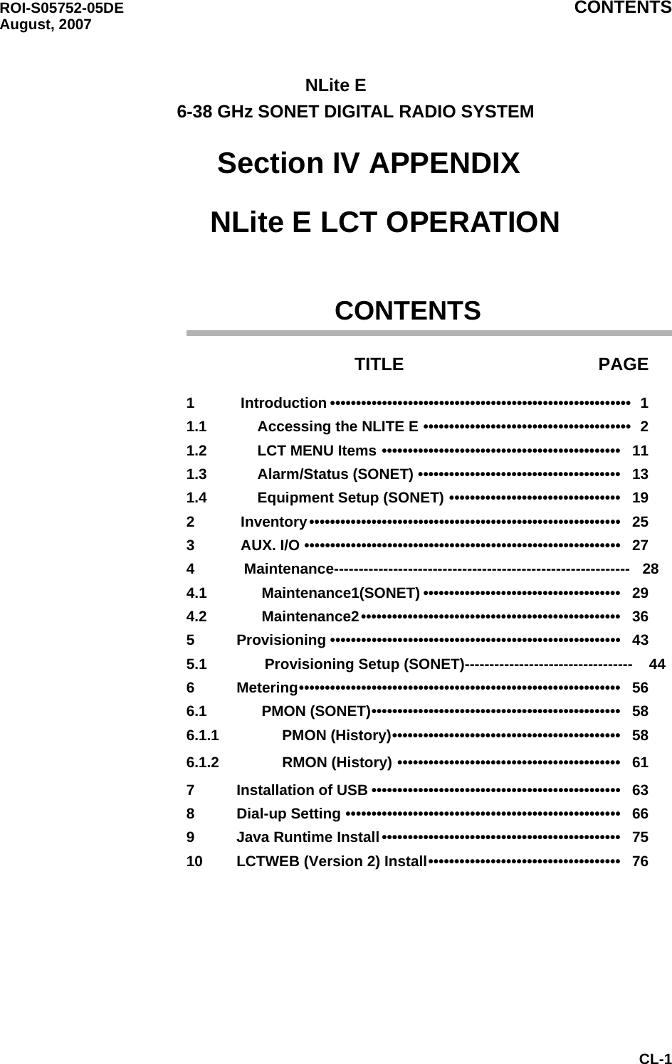
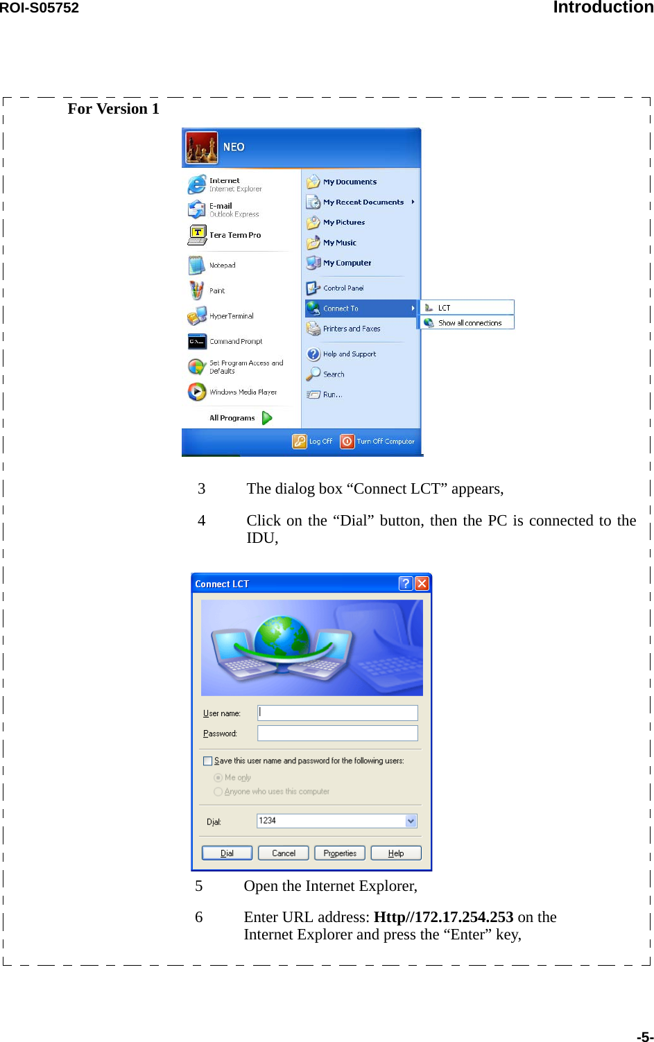
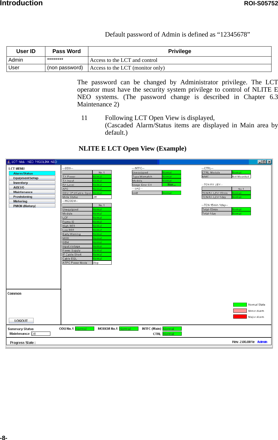
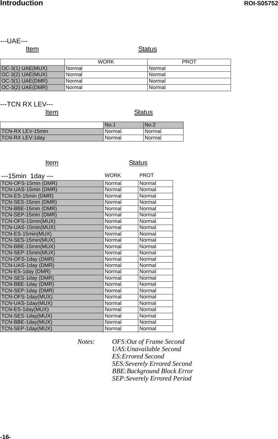
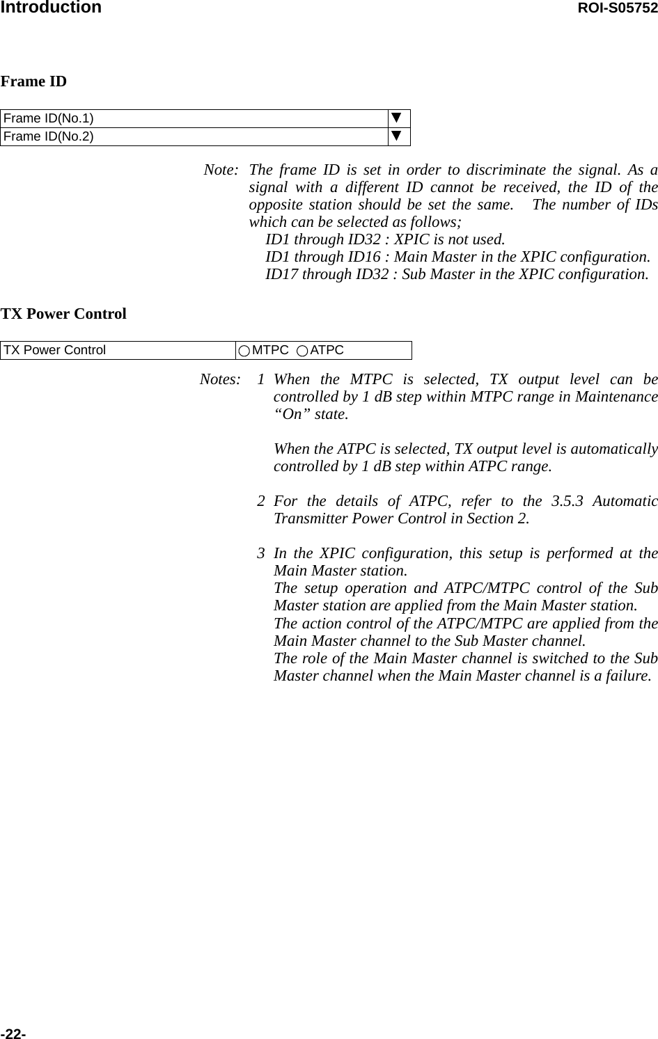
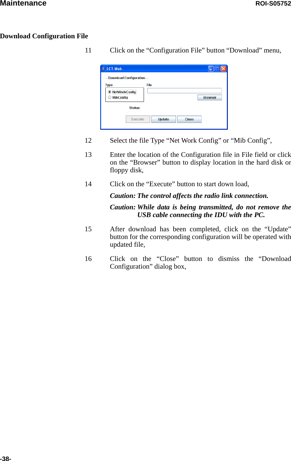
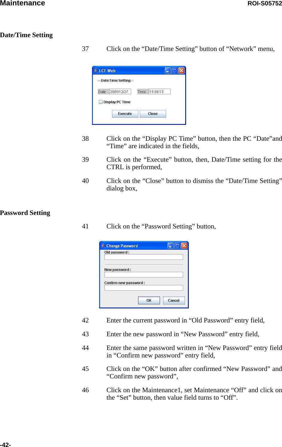
![ROI-S05750 INITIAL LINE UP3-34Chart 3-11 Meter ReadingStep Procedure1 Connect the PC to the LCT port on the NLite E IDU using USB cable, (see Fig. 3-2)2 Enter Login name “Admin”, enter Admin password and press the “Login” button,3 Click “Metering” button in LCT Menu, LCT MENUAlarm/StatusEquipment SetupInventoryAUX I/OMaintenanceProvisioningMeteringPMON(History)4 Then, the values of Metering items are displayed as follows: 1+1 Configuration----Metering---No.1 No.2TX Power [dBm]*1 +19 +19RX Level [dBm] -49.5 -49.7Power Supply [V] *2 -45 -45BER *3 0.0E-10 Calculating1+0 Configuration----Metering---TX Power [dBm]*1 +19RX Level [dBm] -50Power Supply[V] *2 -45BER *3 1.10E-10](https://usermanual.wiki/NEC-of-America/58155.User-Manual-Part-4/User-Guide-1070885-Page-17.png)
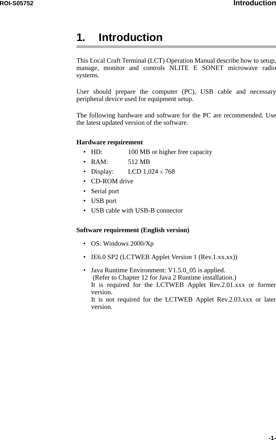
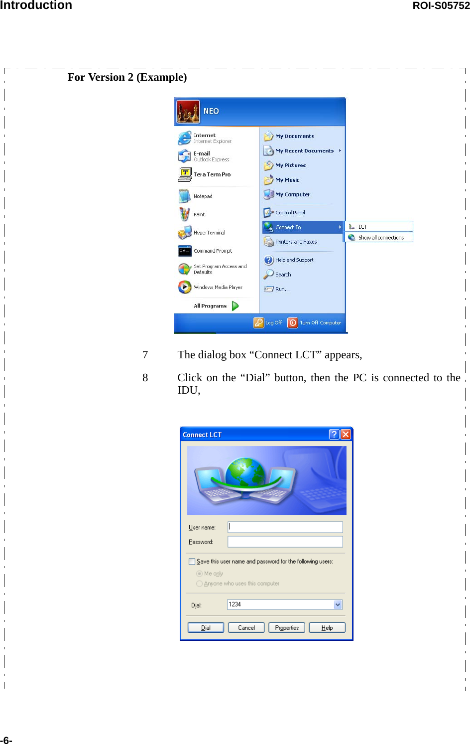
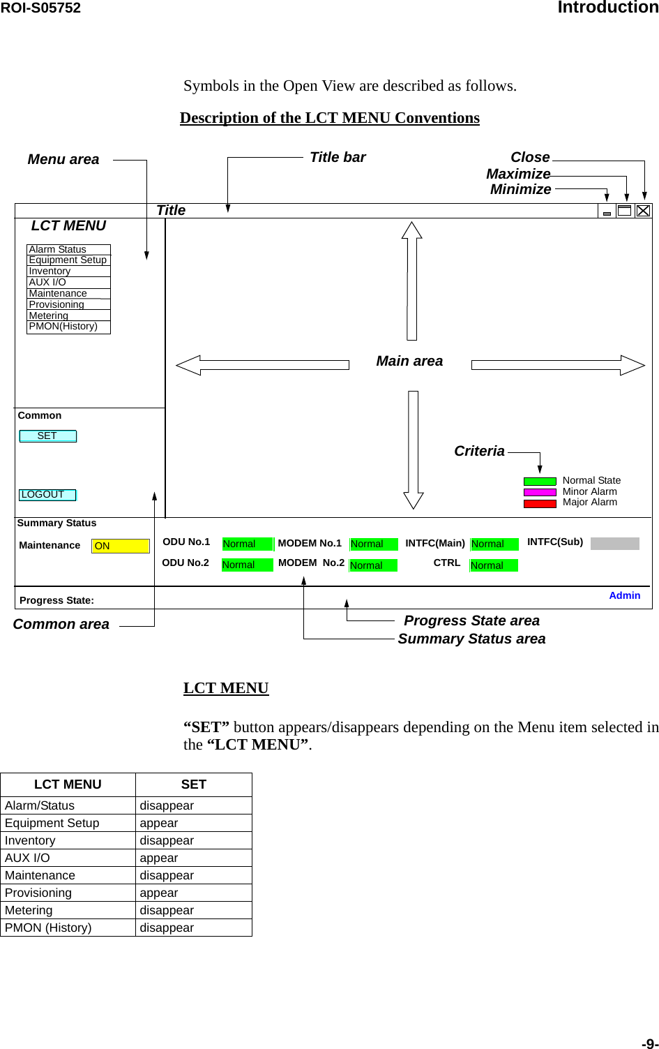
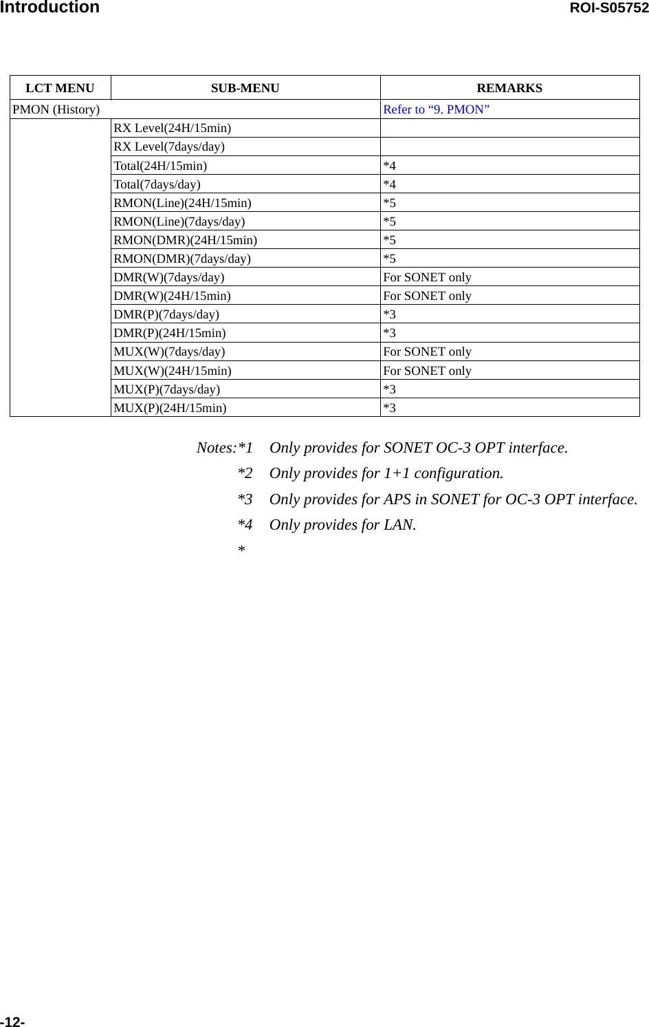
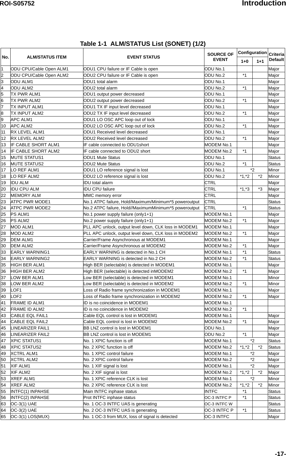
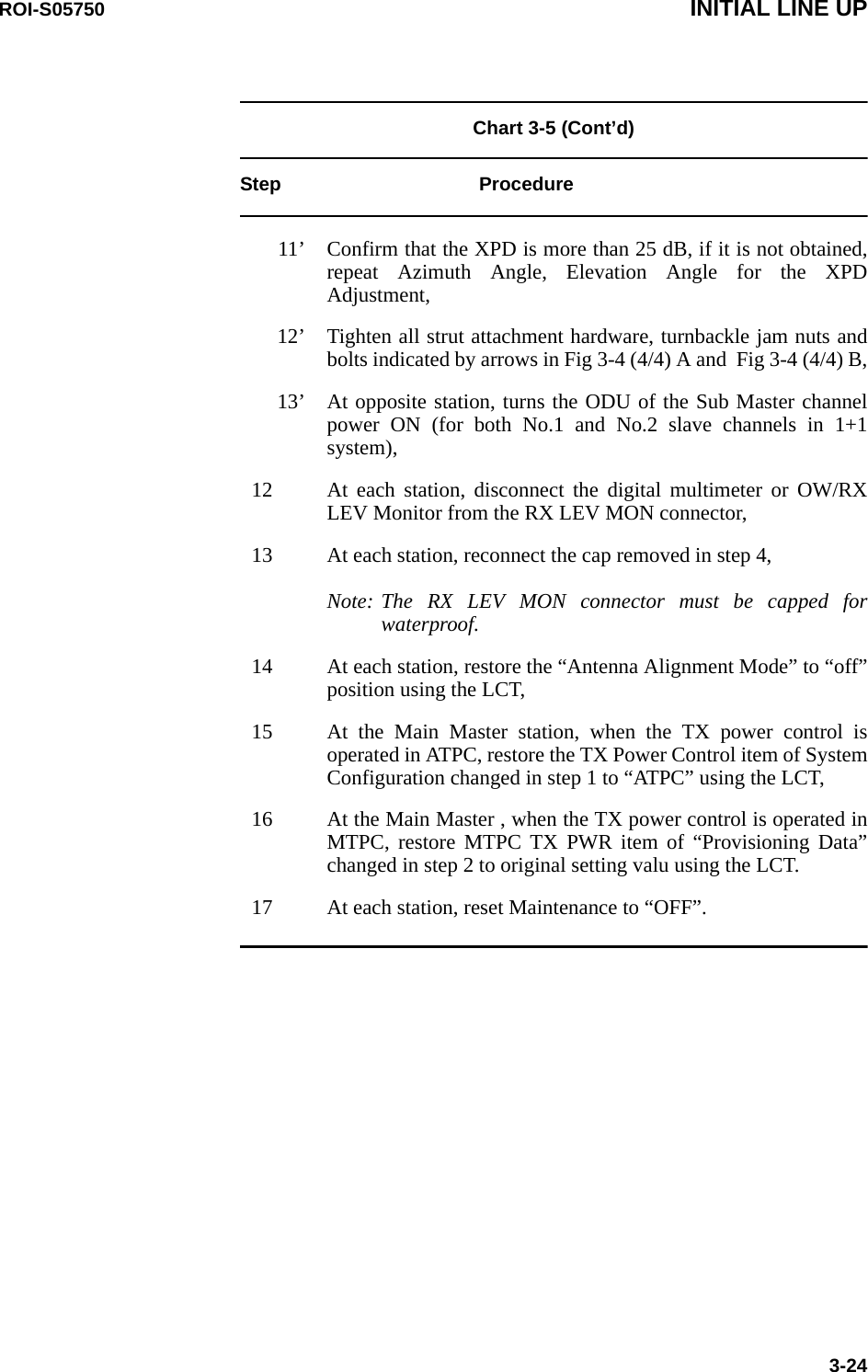
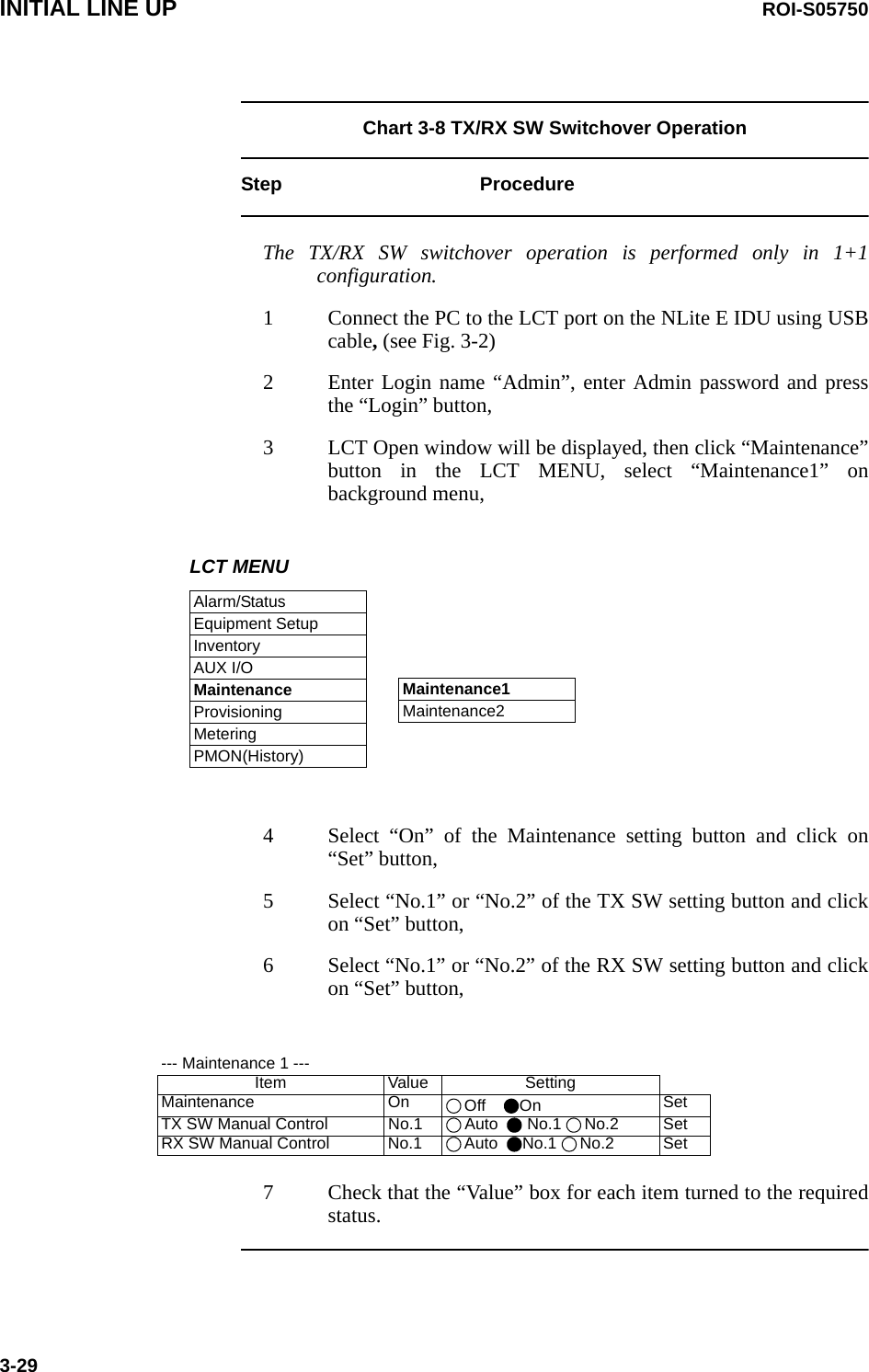
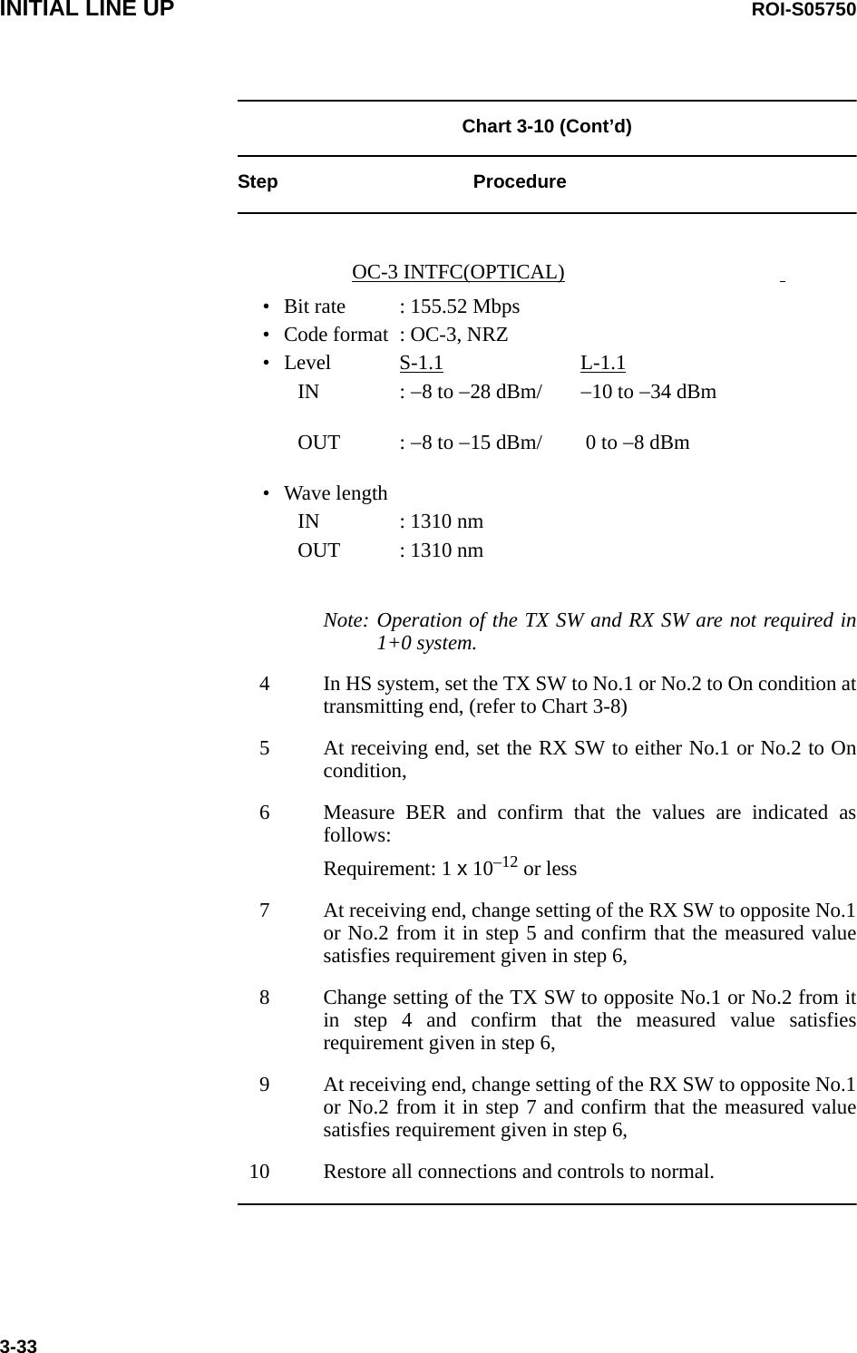
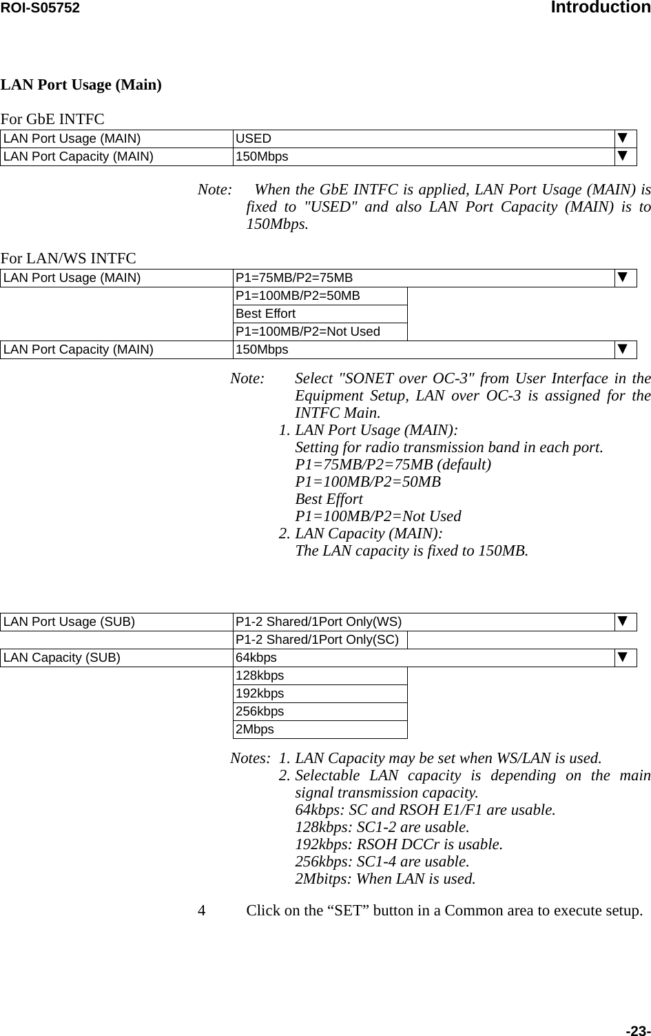
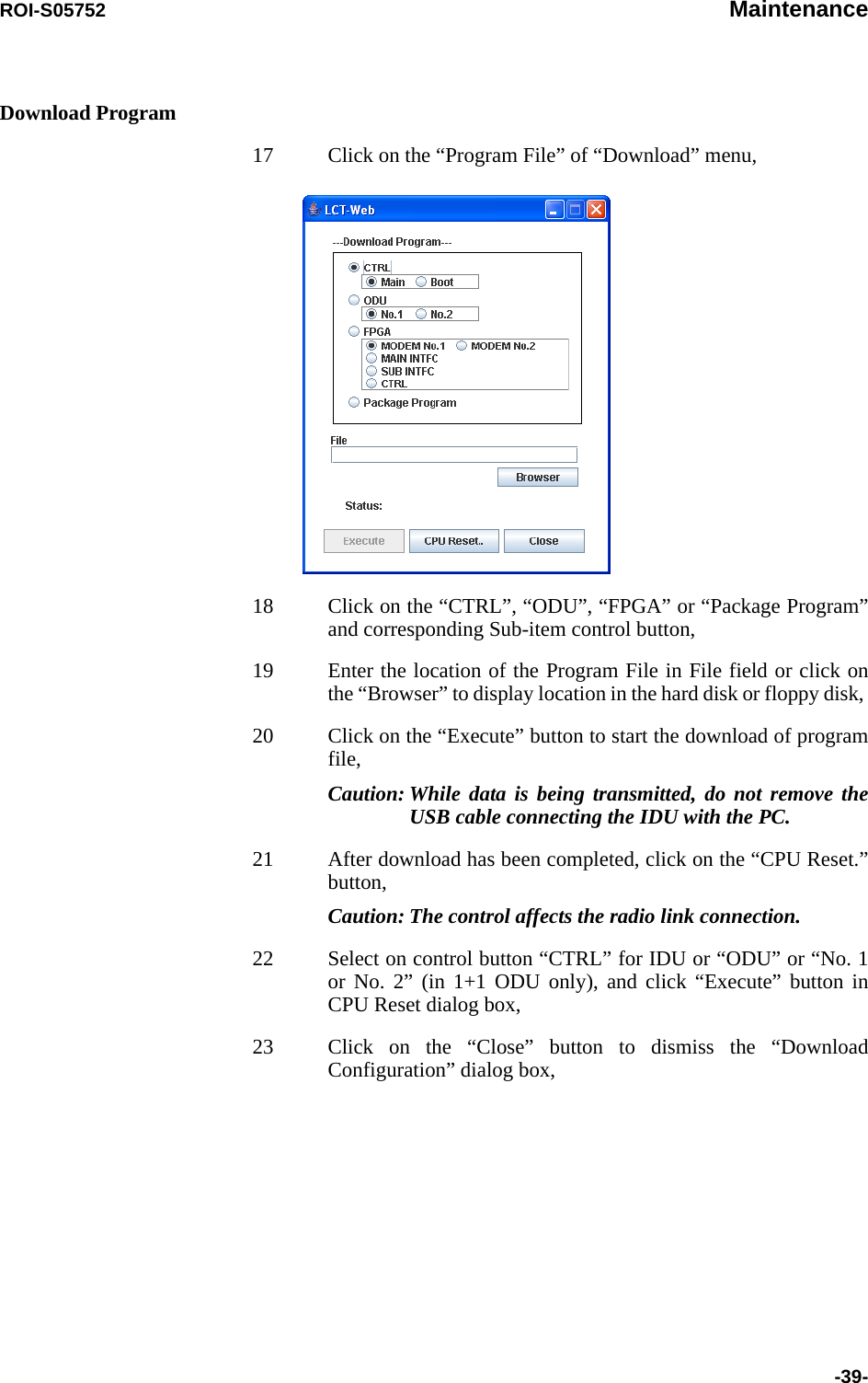
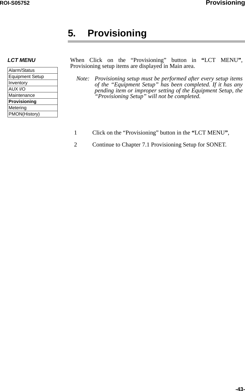
![ROI-S05752 Introduction-19-1.4 Equipment Setup (SONET)Note: Click on the “SET” button in Common area after every setting items has been entered.OC-3 (OPTICAL) Equipment Setup (Sample) 1 Click on the menu button “User Interface” and select corresponding item,User Interface SONET OC-3Redundancy Setting 1+1(Hot Standby TERM) INTFC(Main) OC-3(OPTICAL)INTFC(Sub) NOT USEDXPIC Usage Not Used Used(Main Master) Used(SUB Master)APS Function Unavailable AvailableModulation Scheme 128QAMTransmission Capacity 156MBTX RF Frequency [MHz] 6048.975RX RF Frequency [MHz] 6301.015Frame ID ID1TX Power Control MTPC ATPCLAN Port UsageLAN Capacity---ODU FREQ INFO---TX Start Frequency [MHz] 5930.375TX Stop Frequency [MHz] 6162.633Frequency Step [MHz] 0.050Shift Frequency [MHz] 252.040Upper/Lower LOWER SUB Band EUser Interface Redundancy Setting INTFC(Main) INTFC(Sub) XPIC Usage APS Function Modulation SchemeTransmission Capacity](https://usermanual.wiki/NEC-of-America/58155.User-Manual-Part-4/User-Guide-1070885-Page-39.png)
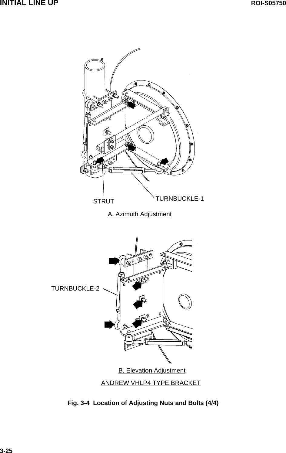
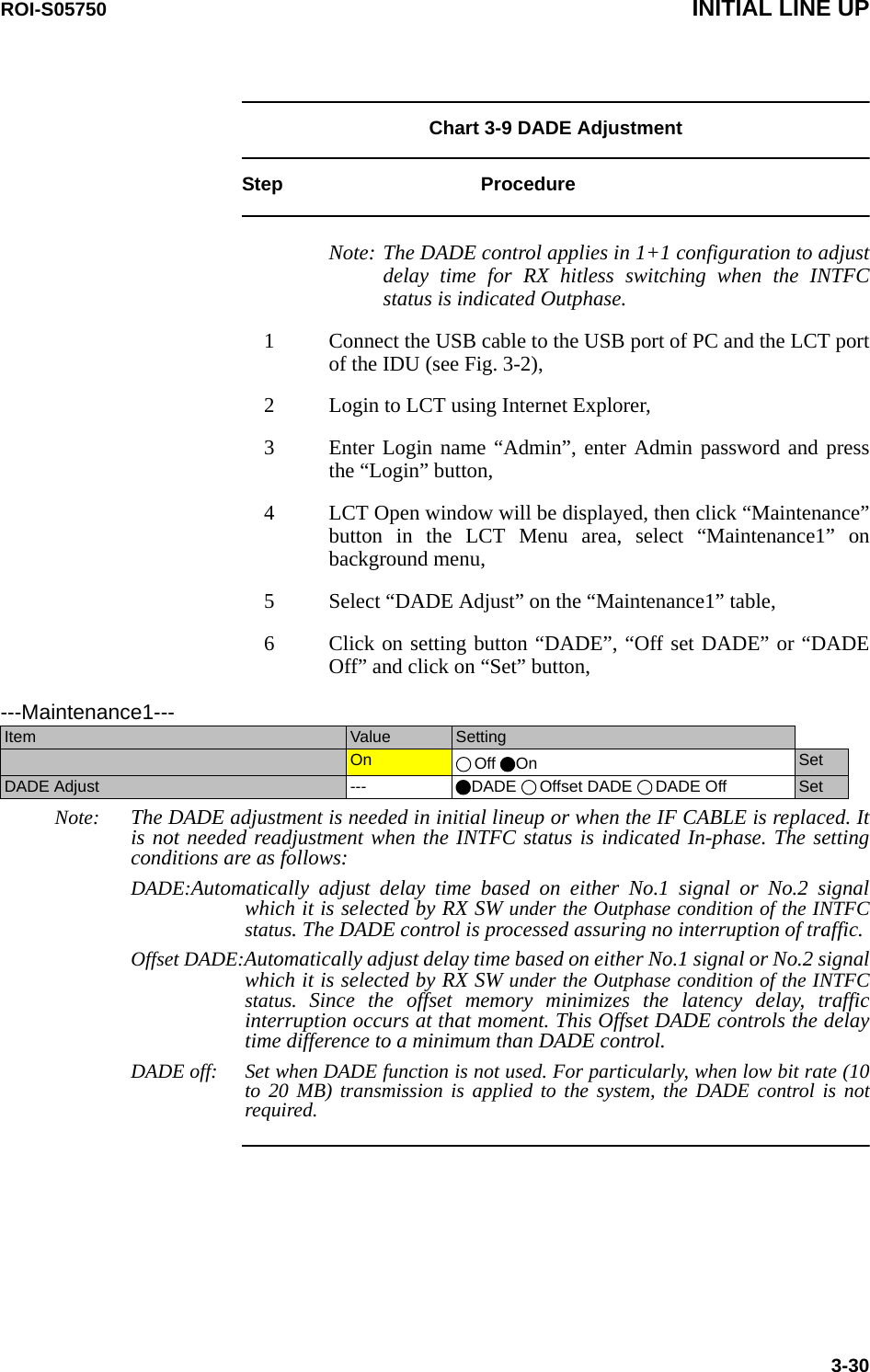
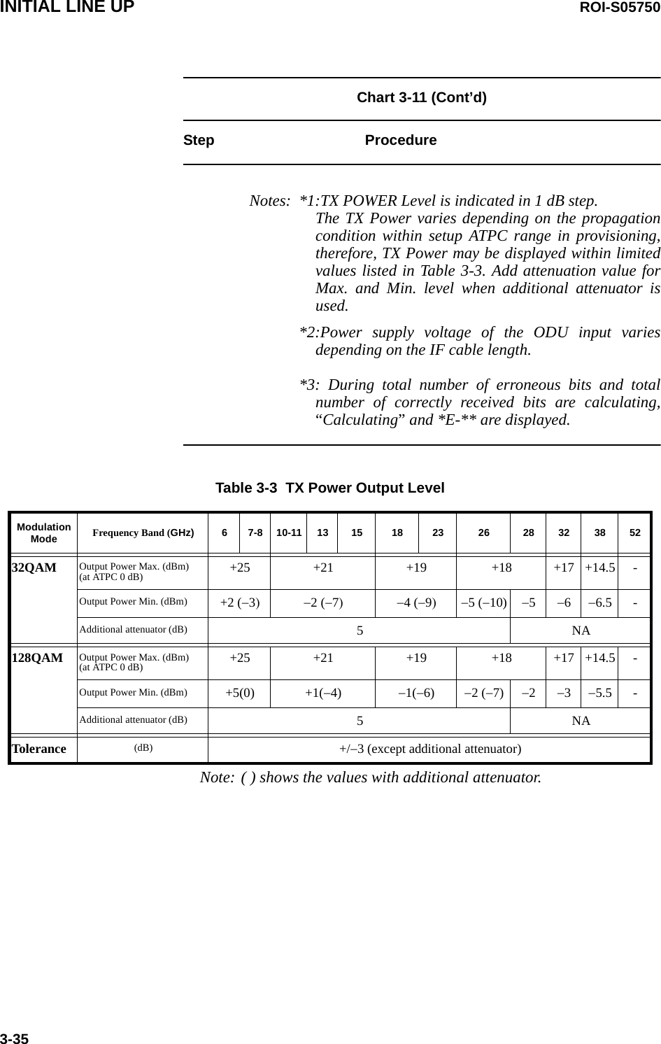
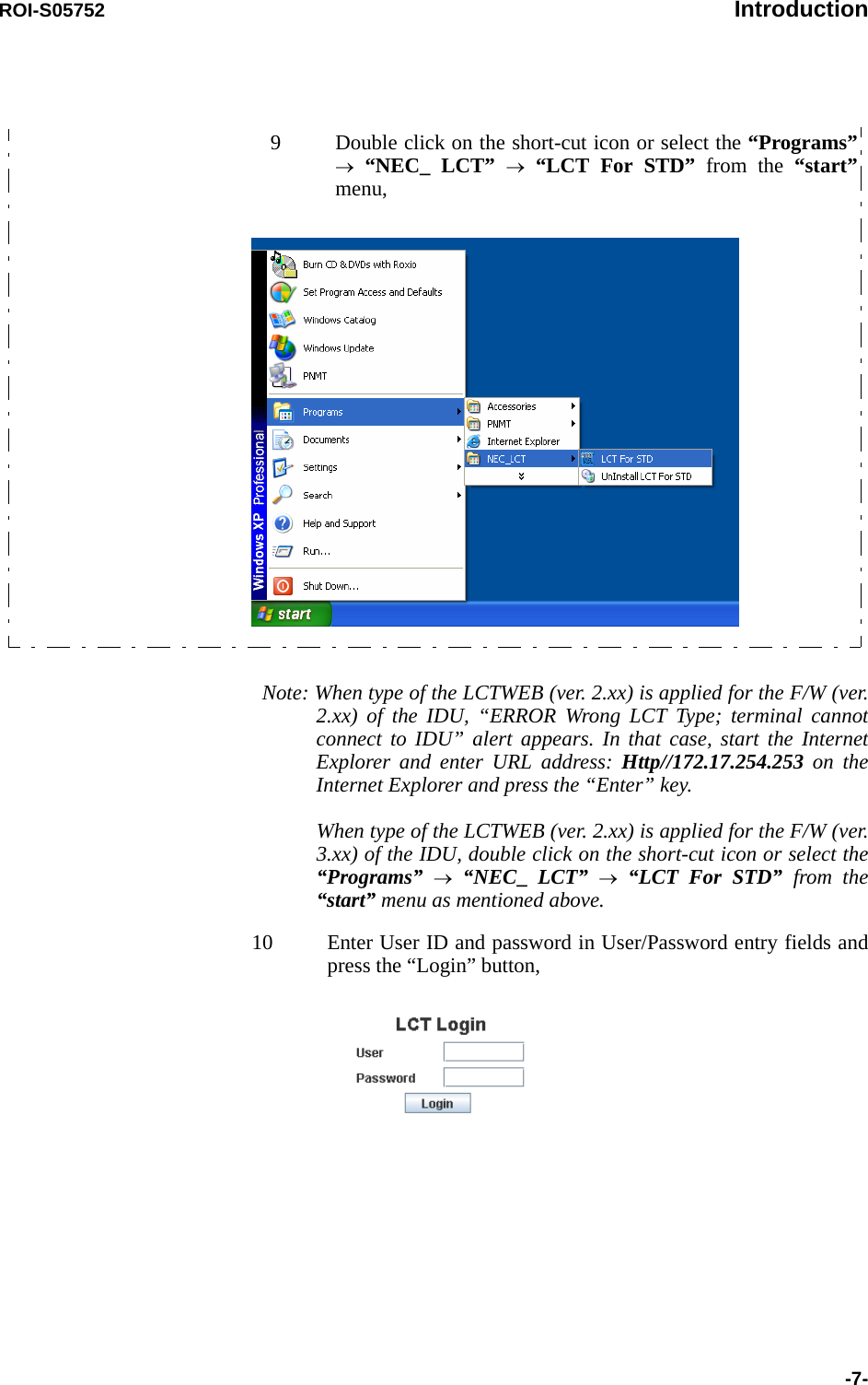
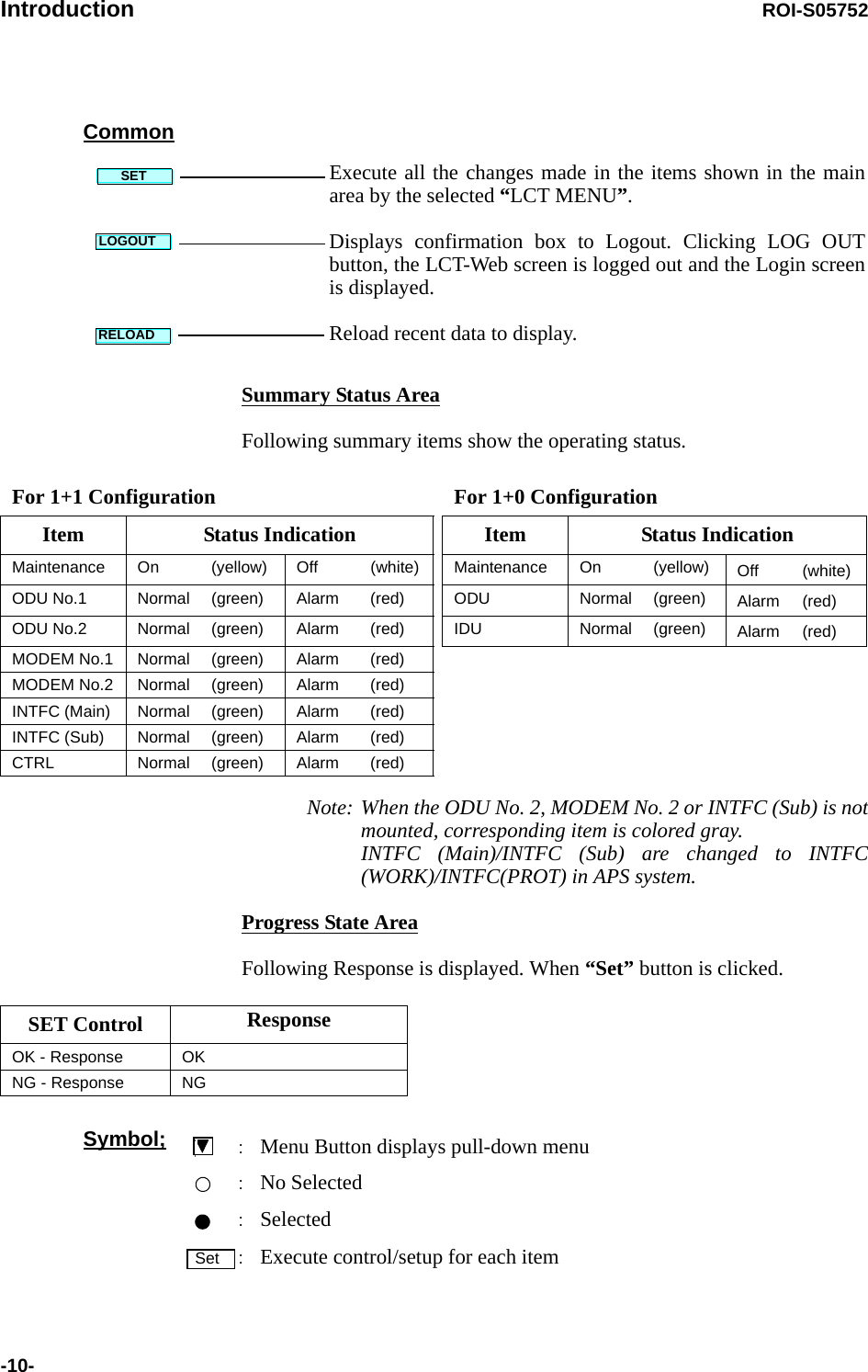
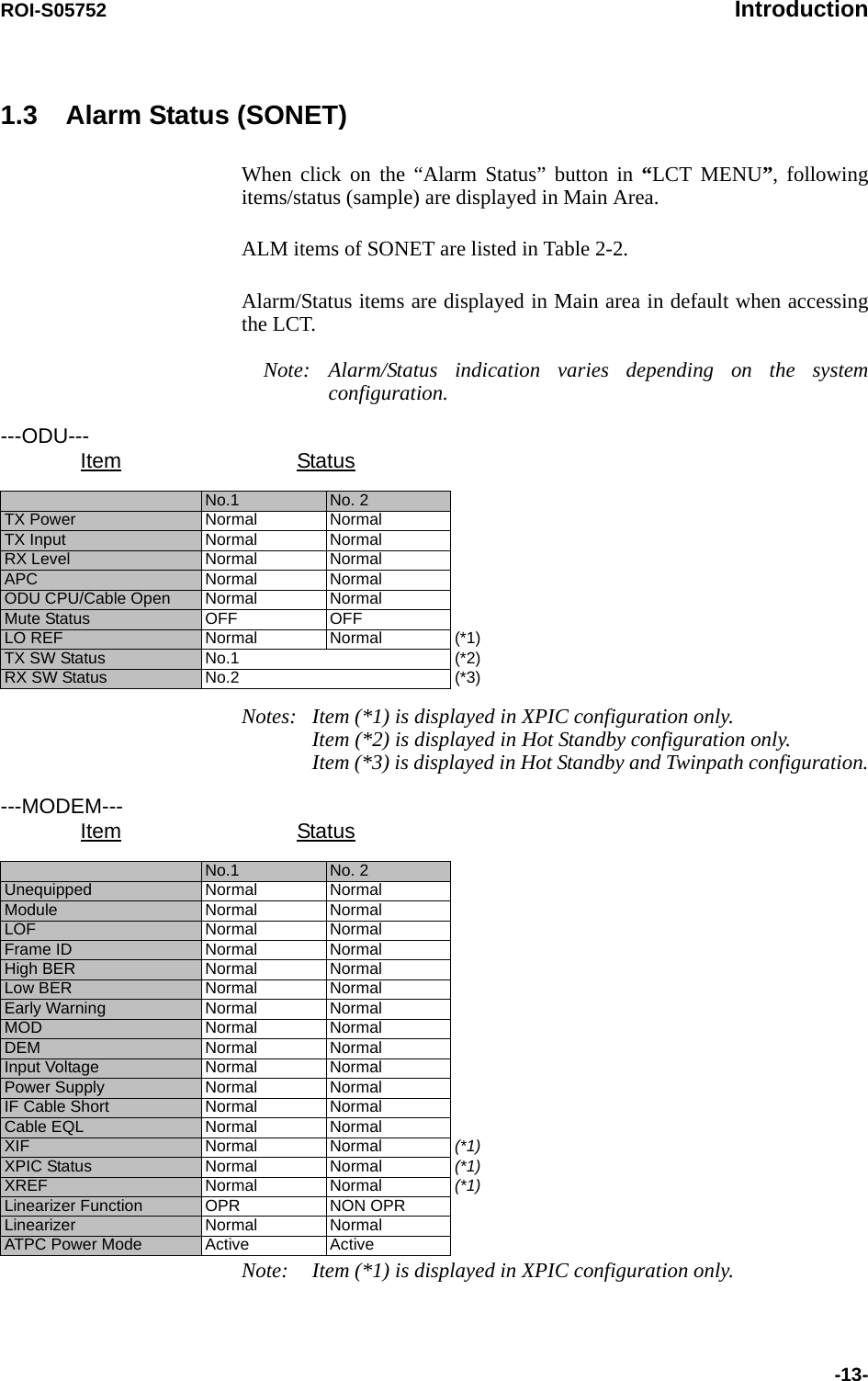
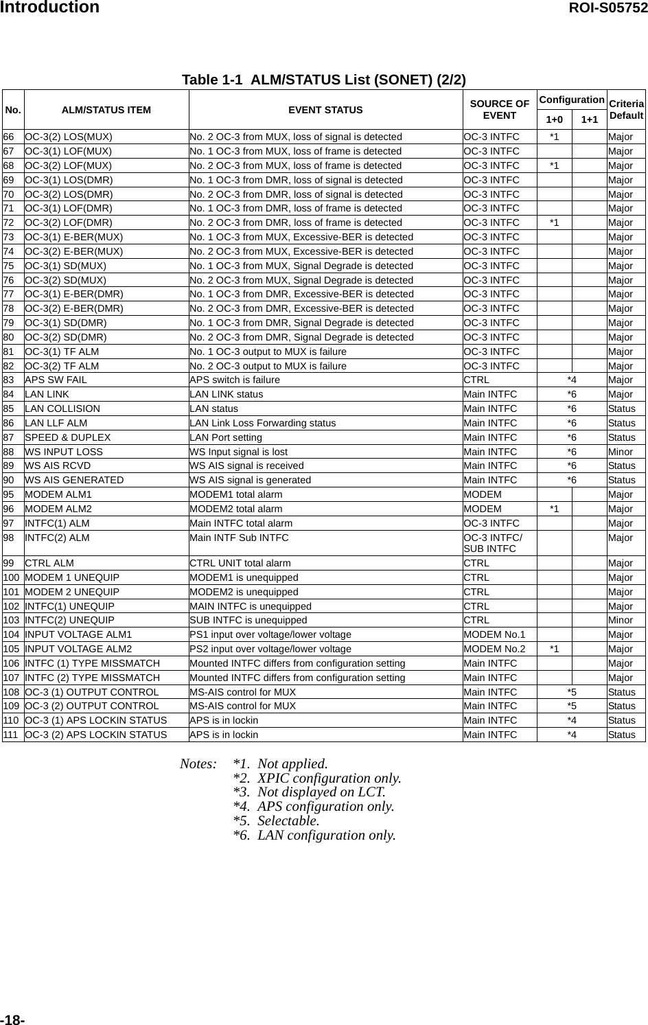
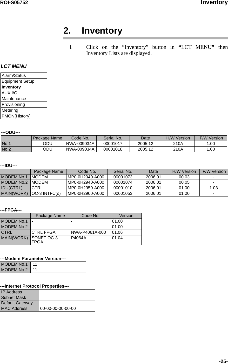
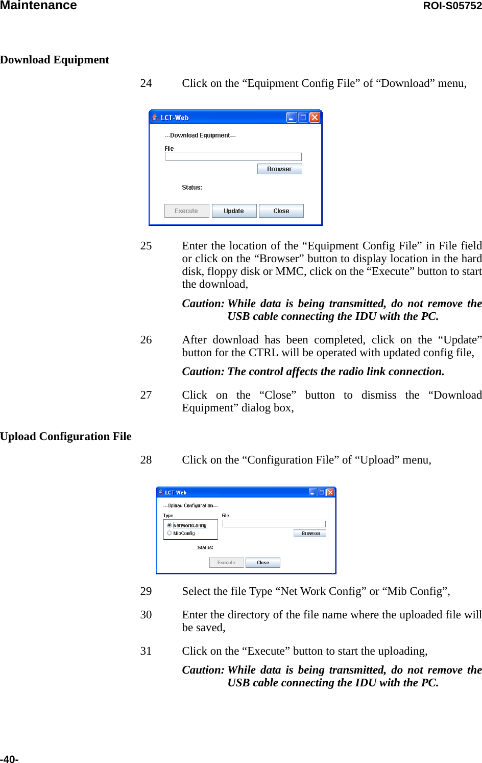
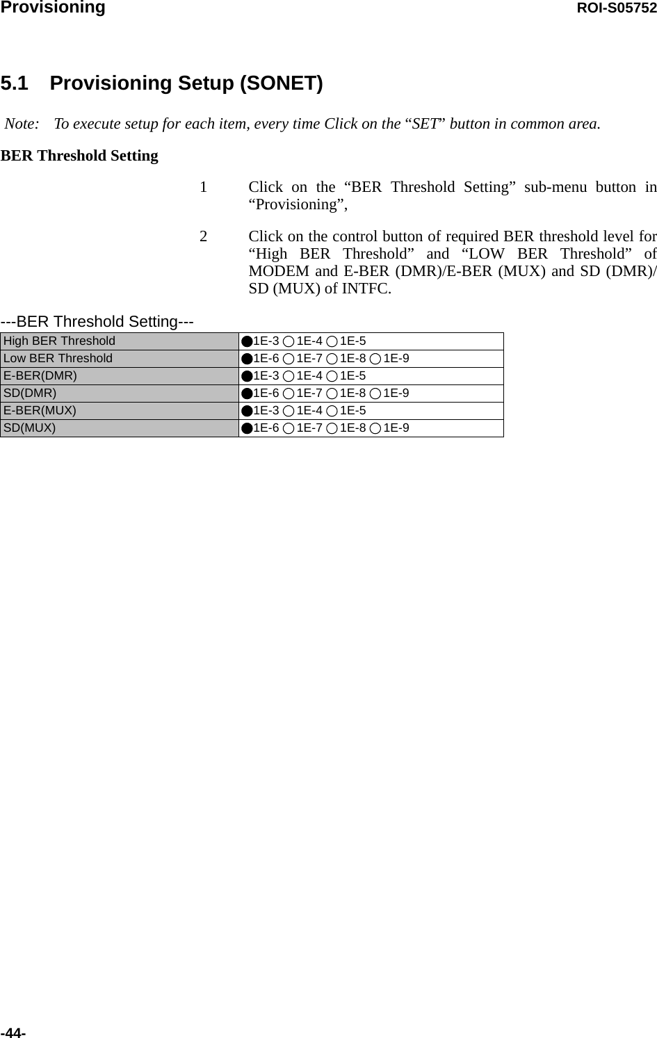
![ROI-S05752 Introduction-21-channel.(*) INTFC(Main)/INTFC(Sub) are changed to INTFC (WORK)/INTFC(PROT) in APS system.RF FrequencyNotes: 1 Set different values for No.1 TX frequency and No.2 TX frequency in the Twinpath configuration.2 Depending on the ODU type, there are two modes for the RF frequency setup.1. When the transmitting frequency is set, the receiving frequency is automatically assigned. 2. When the transmitting frequency is set, the receiving frequency is automatically assigned and assignment of it in manual is also available by changing the RX RF frequency values which is automatically assigned. 3 The transmitting frequency for the Main Master and Sub Master must be set the same and also the receiving frequency. The frequency setup must be performed at the Main Master station first and then, Sub Master station. The entered TX RF frequency value should be within the Start and Stop frequency range of Sub-Band which is indicated on the Name Plate of each ODU. For details, refer to the Appendix RADIO FREQUENCY PLAN OF THE NLITE E NEO in Section 1.Caution: For the 6/7/8/10 GHz band, the BPF of TX and RX of the ODU are adjusted to each assigned frequency. Then, to change the RF channel frequency, both BPFs replacement and LCT setup are required.TX Frequency and RF Frequency for No.1 and No.2 are displayed in Twinpath configuration.APS Function Unavailable AvailableTX RF Frequency(No.1) [MHz]TX RF Frequency(No.2) [MHz]RX RF Frequency(No.1) [MHz]RX RF Frequency(No.2) [MHz]](https://usermanual.wiki/NEC-of-America/58155.User-Manual-Part-4/User-Guide-1070885-Page-41.png)
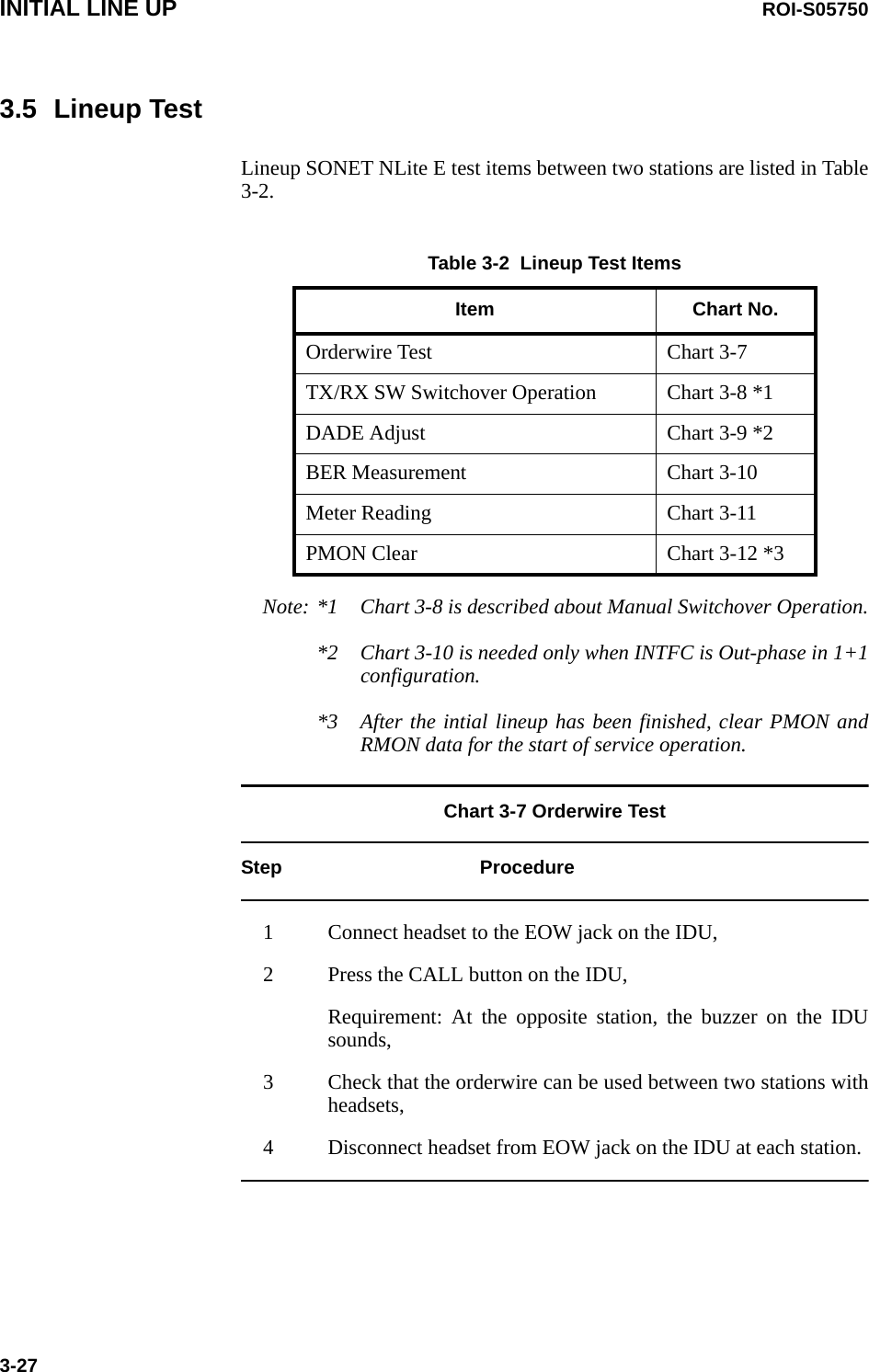
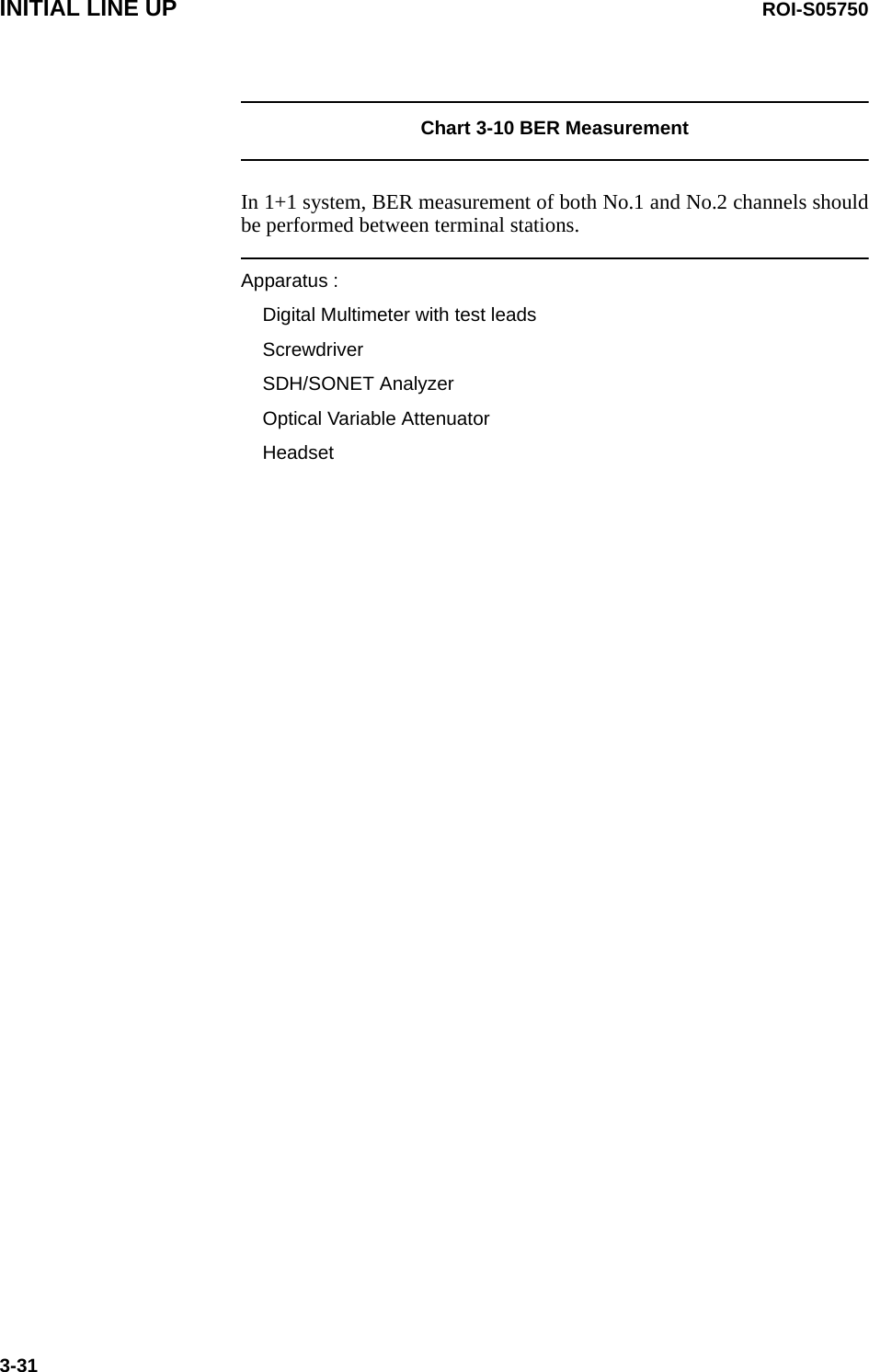
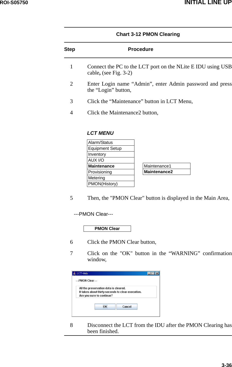
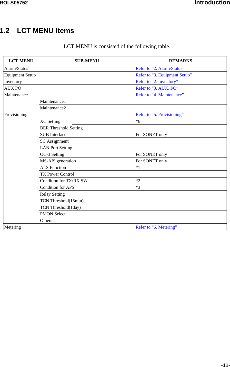
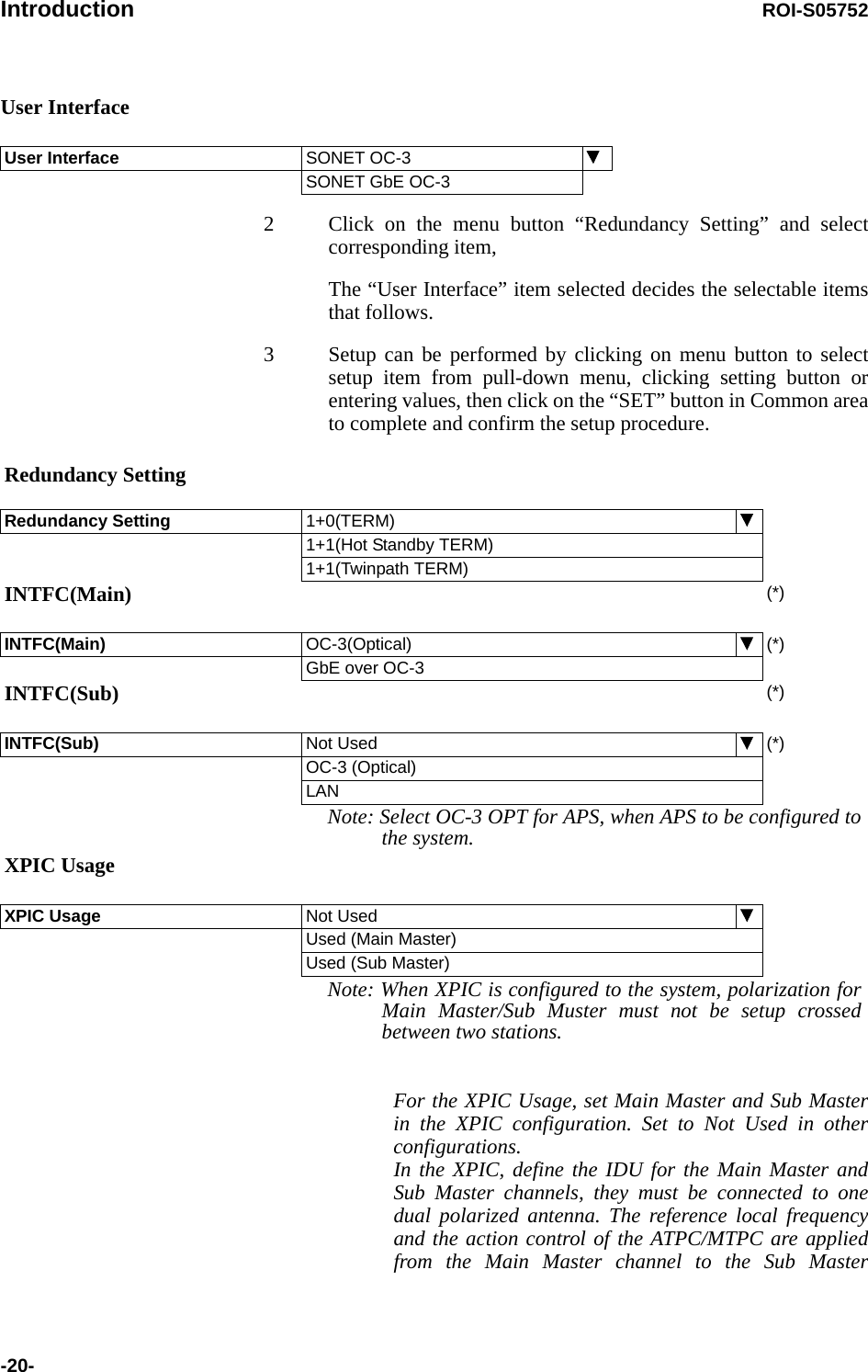
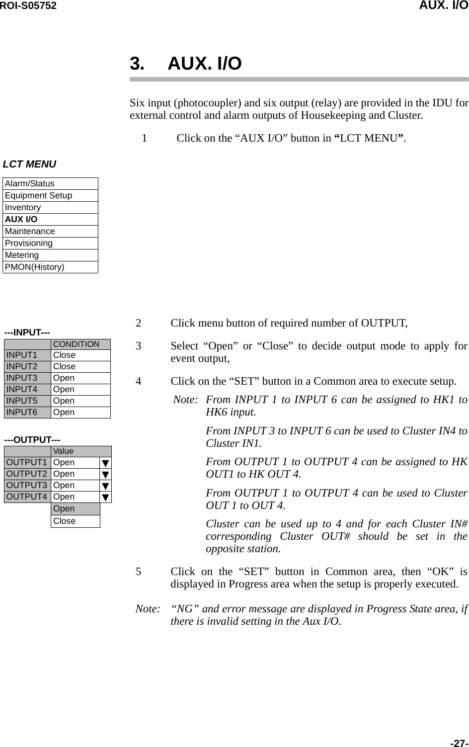
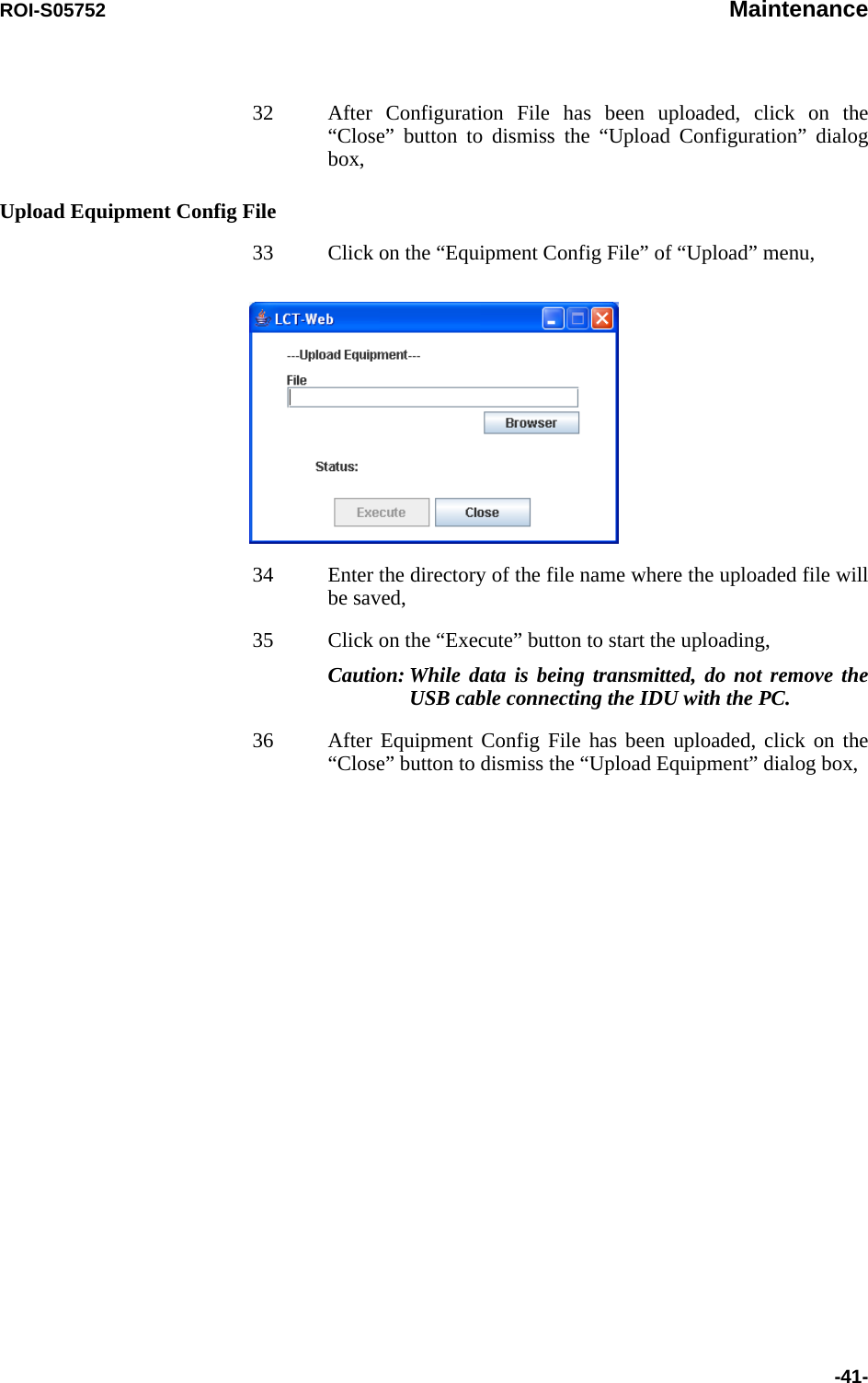
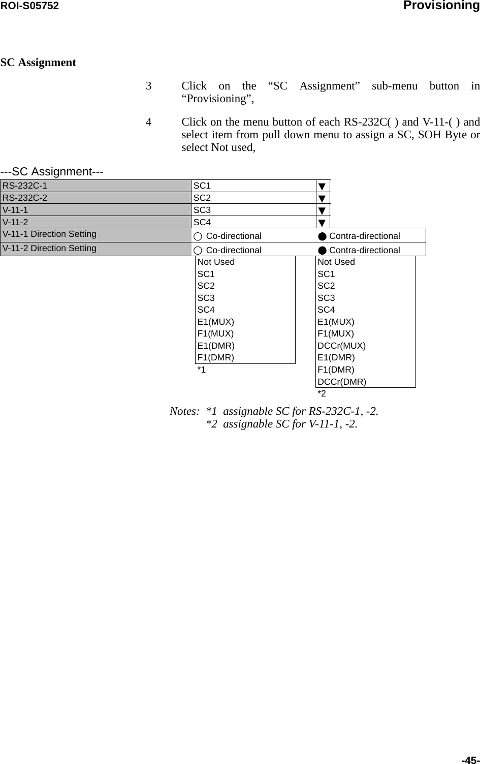
![Introduction ROI-S05752-24-5 Click on the “SET” button in Common area, then “OK” is displayed in Progress area when the setup is properly executed.Note: “NG” and error message are displayed in Progress State area, if there is invalid setting in the Equipment Setup.---ODU FREQ INFO---TX Start Frequency (No.1) [MHz]TX Stop Frequency (No.1) [MHz]Frequency Step (No.1) [MHz]Shift Frequency (No.1)[MHz]Upper/Lower (No.1)Sub Band (No.1)TX Start Frequency (No.2) [MHz]TX Stop Frequency (No.2) [MHz]Frequency Step (No.2) [MHz]Shift Frequency (No.2) [MHz]Upper/Lower (No.2)Sub Band (No.2)](https://usermanual.wiki/NEC-of-America/58155.User-Manual-Part-4/User-Guide-1070885-Page-44.png)
![Inventory ROI-S05752-26- ---Software Key---Category Item StatusCategory & RedundancyCapacity 156 [MB]Redundancy 1+1Precheck Enable ONCapacity (previous) 156 [MB]Redundancy (previous) 1+1Bit Rate Free Bit Free FreePrecheck Enable ONBit Free (previous) FreeLAN INTFC LAN AvailablePrecheck Enable ONLAN (previous) AvailableXPIC XPIC AvailablePrecheck Enable ONXPIC (previous) AvailableNotes: *1 Availability of Capacity & Redundancy Key at the present. *2 Availability of Bit Free Key at the present.*3 Availability of LAN INTFC Key at the present. *4 Availability of XPIC Key at the present.*5 Comparing contents of the former Software Key with Up dating one.*6 Former status of the Key is indicated as previous.*3*4*1*5*5*5*6*6*6*2*6*5](https://usermanual.wiki/NEC-of-America/58155.User-Manual-Part-4/User-Guide-1070885-Page-46.png)
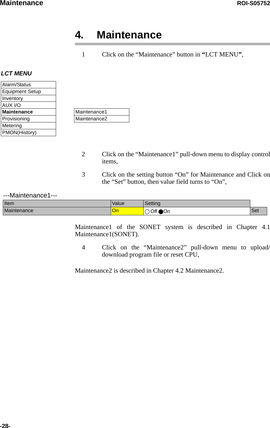
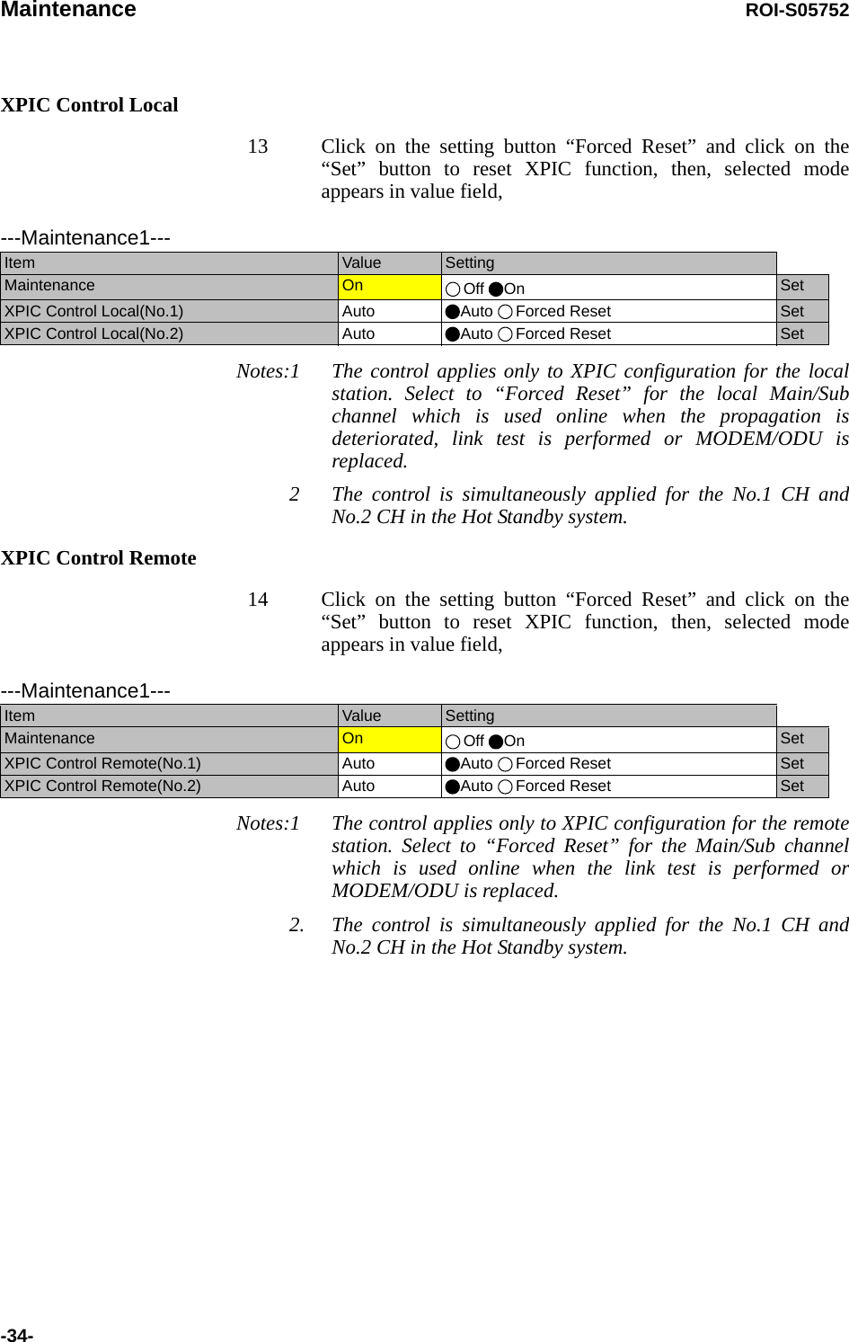
![ROI-S05752 Maintenance-29-4.1 Maintenance1(SONET)---Maintenance1---Item Value SettingMaintenance On Off On SetTX SW Manual Control Auto Auto No.1 No.2 SetRX SW Manual Control Auto Auto No.1 No.2 SetRX SW Maintenance Mode ManualATPC Manual Control(No.1) On Off On [dB] SetATPC Manual Control(No.2) Off Off On SetTX Mute Control(No.1) Off Off On SetTX Mute Control(No.2) Off Off On SetCW Control(No.1) Off Off On SetCW Control(No.2) Off Off On SetAPS Manual Control Auto Auto Working Protection SetAPS Maintenance Mode ManualIF Loopback(No.1) Off Off On SetIF Loopback(No.2) Off Off On SetMain Loopback (Near End) Off Off On SetMain Loopback (Far End) Off Off On SetLAN Device Reset SetLinearizer Control(No.1) Auto Auto Forced Reset SetLinearizer Control(No.2) Auto Auto Forced Reset SetALS Restart --- 2sec 90sec SetXPIC Control Local(No.1) Auto Auto Forced Reset SetXPIC Control Local(No.2) Auto Auto Forced Reset SetXPIC Control Remote(No.1) Auto Auto Forced Reset SetXPIC Control Remote(No.2) Auto Auto Forced Reset Set---Offline Maintenance---DADE Adjust --- DADE Offset DADE DADE Off SetRF SUB Band Select(No.1) --- A SetRF SUB Band Select(No.2) --- A SetAntenna Alignment Mode(No.1) Off Off On SetAntenna Alignment Mode(No.2) Off Off On Set](https://usermanual.wiki/NEC-of-America/58155.User-Manual-Part-4/User-Guide-1070885-Page-49.png)
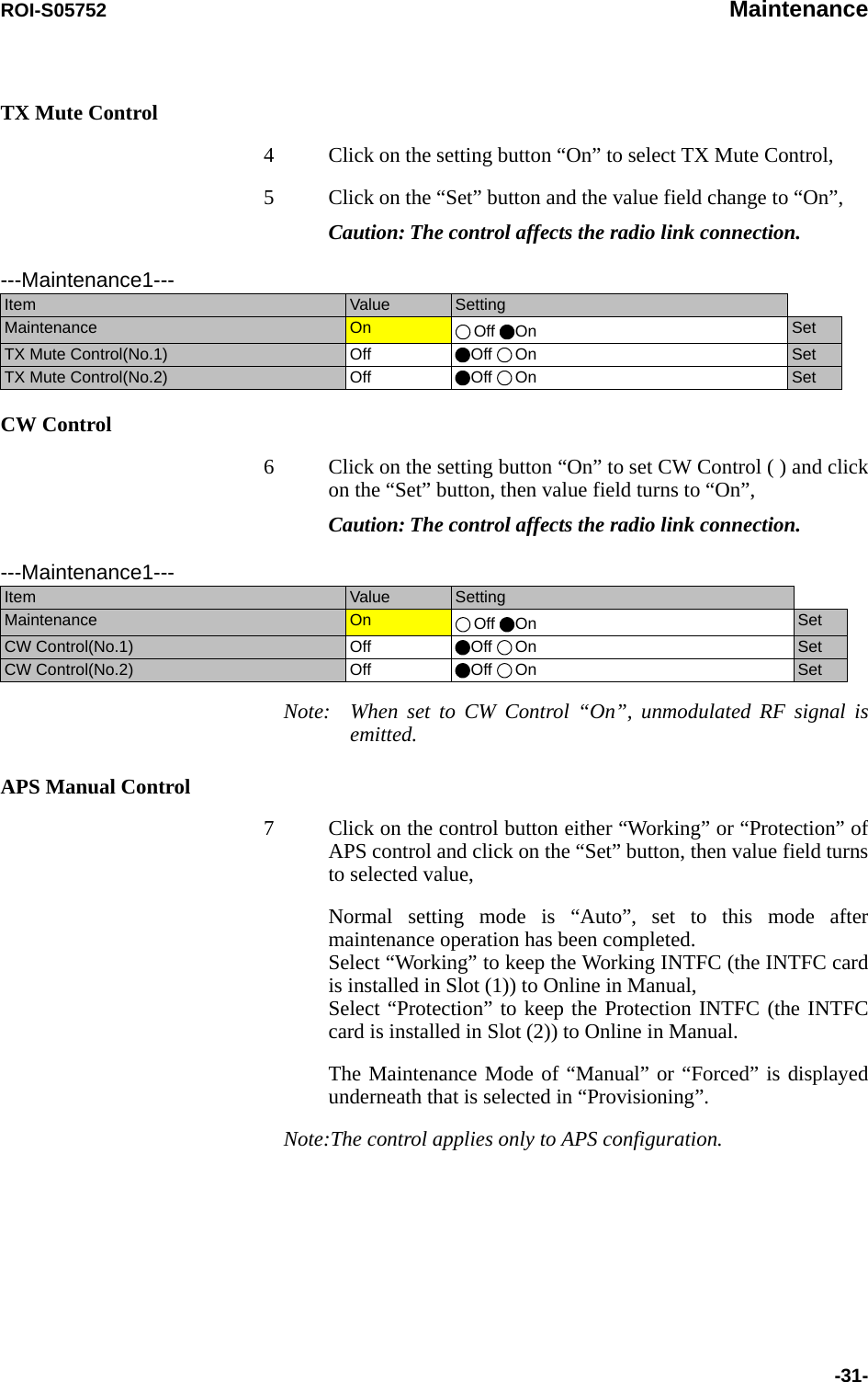
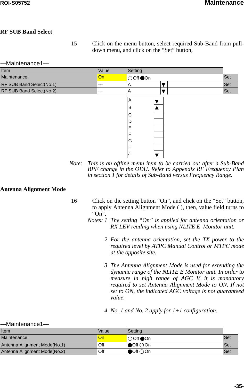
![Maintenance ROI-S05752-30-TX SW Manual Control1 Click on the setting button “On” of the “Maintenance” and click on the “Set” button, then value field of the Maintenance turns from “Off” to “On”.In Maintenance “On” mode, external parallel alarm outputs excepts CPU and PS ALM are masked and automatic control is inhibited.Control operation using LCT must be performed in Maintenance “On” condition.2 Click on the setting button “Auto”, “No. 1” or “No. 2” TX SW to select TX SW control mode and Click on the “Set” button, then the value field of the corresponding SW manual control change to the selected mode.Auto: Normal operation modeNo. 1 or No. 2: Manual control modeATPC Manual Control3 Click on the setting button “On” and enter attenuation value within ATPC range, then click on the “Set” button,In the XPIC configuration, the ATPC/MTPC can not be set in the Sub Master station. The setup is applied from the Main Master station.Note *1 Additional attenuator from 0 to 5 dB can be added.---Maintenance1---Item Value SettingMaintenance On Off On SetTX SW Manual Control Auto Auto No.1 No.2 SetRX SW Manual Control Auto Auto No.1 No.2 Set---Maintenance1---Item Value SettingMaintenance On Off On SetATPC Manual Control(No.1) On Off On [dB] SetATPC Manual Control(No.2) Off Off On SetATPC/MTPC Range (SONET)ModulationMode Frequency Band (GHz) 67-8 10-11 13 15 18 23 26 28 32 38128QAM ATPC Range 0 to 20 dB 0 to 20 dBMTPC Range 0 to 20 dB*1 0 to 20 dB](https://usermanual.wiki/NEC-of-America/58155.User-Manual-Part-4/User-Guide-1070885-Page-50.png)
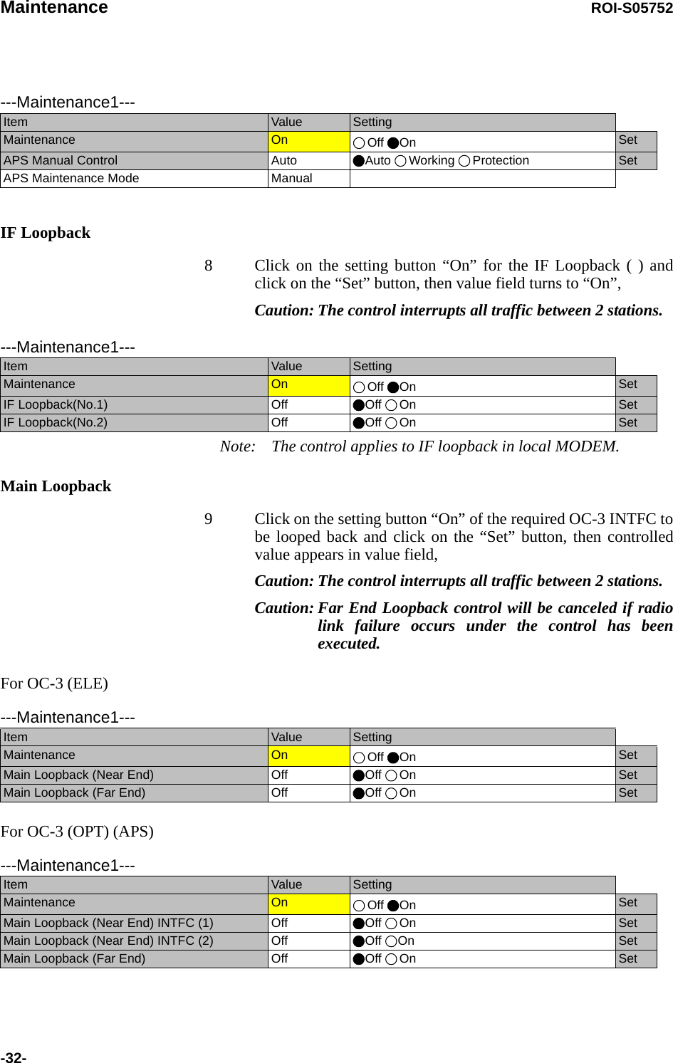
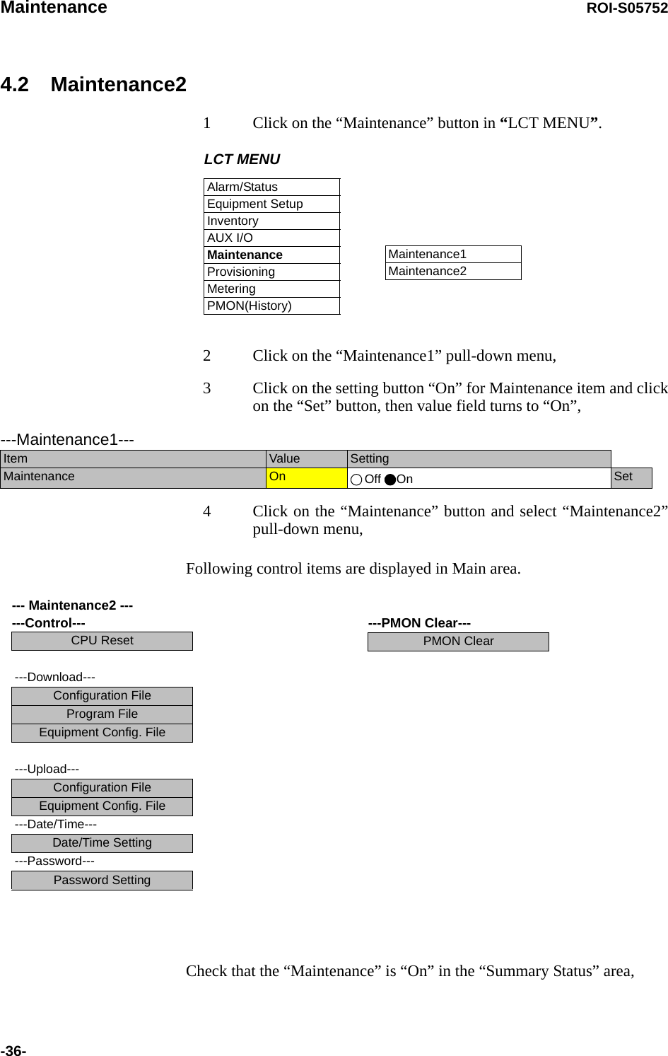
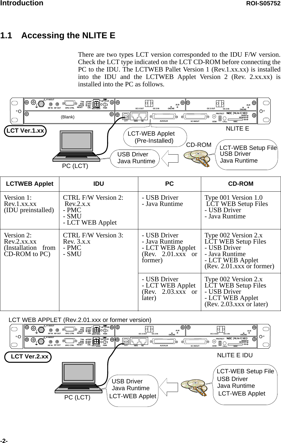
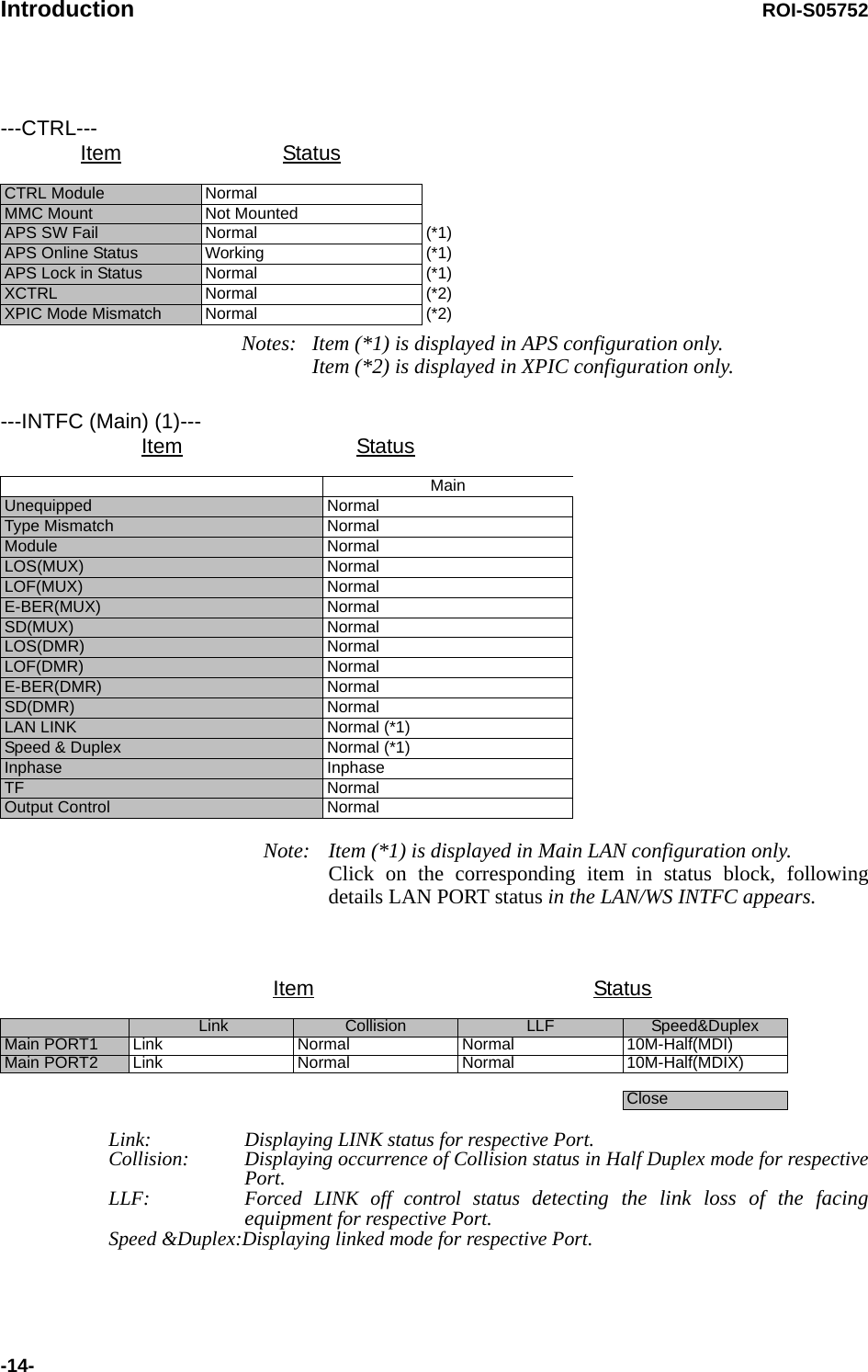
![ROI-S05752 Provisioning-49-OC-3 Setting7 Click on the “OC-3 Setting” sub-menu button in “Provisioning”,8 Click on the either “Disabled” or “Enabled” control button,Note: Refer to Chapter “3.5.6 MS-AIS Generation” in Section 2 for the details. 9 Click on the “Disabled” control button of the ALS,Note: ALS “Enabled” applies only for OC-3 Optical Interface. 10 Click on the “Enabled” and required ALS interval control button when the ALS is configured in the system,Note: Refer to Chapter “3.5.1 Automatic Laser Shutdown Control” in Section 2 for the details. TX Power Control11 Click on the “TX Power Control” sub-menu button in “Provisioning”,12 Enter required values in each control entry field within specified range,(1) ATPC mode in 1+0 or Hot Standby configuration---MS-AIS Generation---MS-AIS Generation Disabled Enabled---ALS------ALS---ALS Function Disabled EnabledALS Interval 60sec 180sec 300sec---TX Power Control--- RangeATPC Threshold Level [dBm] -60.0 -73.0 to -30.0Additional ATT[dB] 0 0 to 5ATPC Range(MAX)[dB] 0 -24 to -0ATPC Range(MIN)[dB] -24ATPC Power Mode Hold MAX MIN](https://usermanual.wiki/NEC-of-America/58155.User-Manual-Part-4/User-Guide-1070885-Page-69.png)
![Provisioning ROI-S05752-50-(2) ATPC mode in Twinpath configuration(3) MTPC mode in Twinpath configuration Notes: 1 No.1 and No.2 are indicated in Twinpath configuration only.2 For Hot Standby configuration, the TX Power Control effects both No. 1 and No. 2 ODUs.3 ATPC/MTPC Range varies depending on RF frequency band and modulation scheme.4 ATPC Threshold level Range varies depending on modulation scheme and RF signal channel separation.5 ATPC power Mode selects the ATPC activation when ATPC function has been failed:Hold: Maintain the current TX output level at the time of the ATPC is malfunction.MAX: Maintain the ATPC maximum TX output level at the time of the ATPC is malfunction.MIN: Maintain the ATPC minimum TX output level at the time of the ATPC is malfunction.6 In the XPIC configuration, this setup is performed at the Main Master station, the ATPC/MTPC can not be set in the Sub Master station. The setup is applied from the Main Master station to the Sub Master station.---TX Power Control--- RangeATPC Threshold Level(No.1) [dBm] -60.0 -73.0 to -30.0ATPC Threshold Level(No.2) [dBm] -60.0 -73.0 to -30.0Additional ATT(No.1) [dB] 0 0 to 5Additional ATT(No.2) [dB] 0 0 to 5ATPC Range(MAX)(No.1) [dB] 0 -20 to -0ATPC Range(MIN)(No.1) [dB] -20ATPC Range(MAX)(No.2) [dB] 0 -20 to -0ATPC Range(MIN)(No.2) [dB] -20ATPC Power Mode Hold MAX MIN---TX Power Control--- RangeMTPC TX Power(No.1) [dB] -20 -20 to 0MTPC TX Power(No.2) [dB] -20 -20 to 0ATPC Threshold Level(No.1) [dBm] -60 -73 to -30ATPC Threshold Level(No.2) [dBm] -60 -73 to -30Additional ATT(No.1) [dB] 0 0 to 5Additional ATT(No.2) [dB] 0 0 to 5](https://usermanual.wiki/NEC-of-America/58155.User-Manual-Part-4/User-Guide-1070885-Page-70.png)
![Provisioning ROI-S05752-54-TCN Threshold (15min 1day)18 Click on the “TCN Threshold (15min)” or “TCN Threshold (1day)” sub-menu button in “Provisioning”,19 Enter required values in threshold OCR (Alarm Occur) and RCVR (Alarm Recover) fields of performance item,Note: Do not mistake the setting such as the OCR ≤ RCVR or RCVR=0.PMON Select20 Click on the “PMON Select” sub-menu button in “Provisioning”,21 Enter required “RX level TCN Thresholdt” level in text field,22 Click on the control button of “SES Activation Condition”,----TCN Threshold (15min)---DMR MUXOCR RCVR OCR RCVR RANGEOFS 900 90 900 90 0 to 900UAS 900 90 900 90 0 to 900ES 900 90 900 90 0 to 900SES 900 90 900 90 0 to 900BBE 1410 150 1410 150 0 to 2159100SEP 900 90 900 90 0 to 900----TCN Threshold (1day)---DMR MUXOCR RCVR OCR RCVR RANGEOFS 65534 650 65534 650 0 to 86400UAS 65534 650 65534 650 0 to 86400ES 65534 650 65534 650 0 to 86400SES 65534 650 65534 650 0 to 86400BBE 135360 13540 13560 13540 0 to 207273600SEP 65534 650 65534 650 0 to 86400---PMON Select---RX Level TCN Threshold [dBm] −82.0SES Activation Condition 30[%] 15[%]](https://usermanual.wiki/NEC-of-America/58155.User-Manual-Part-4/User-Guide-1070885-Page-74.png)
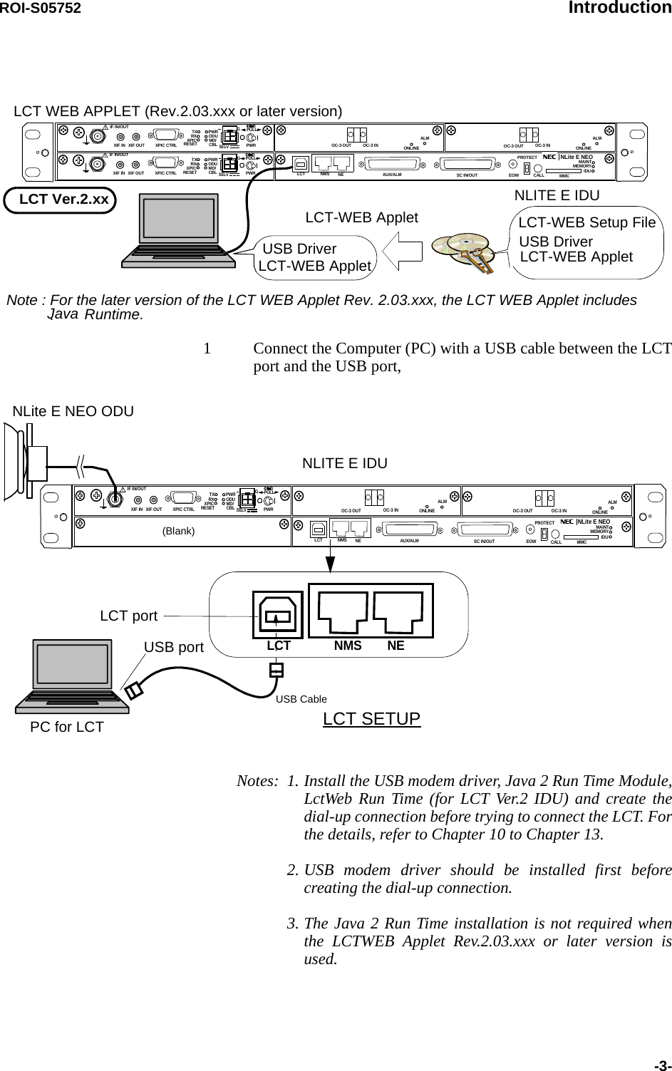
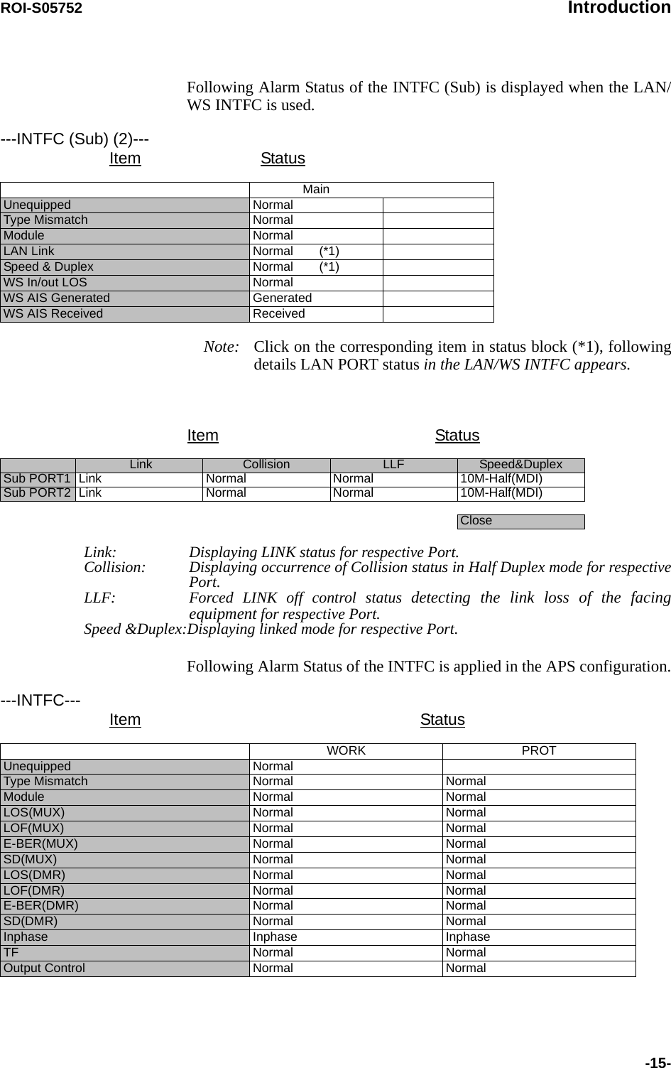
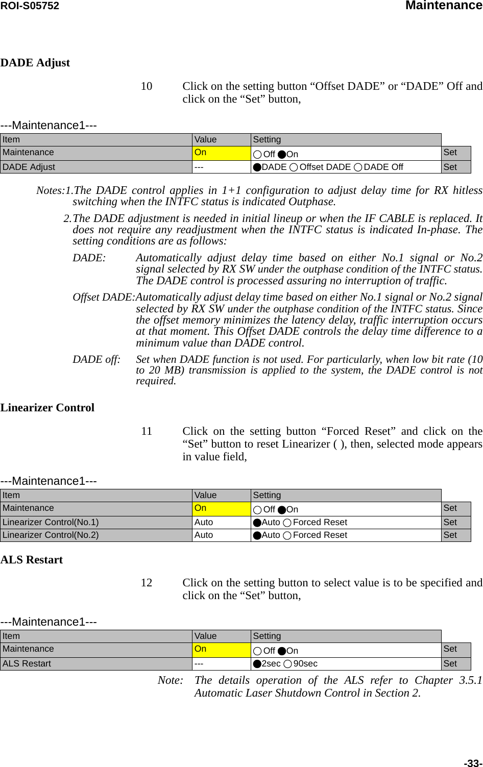
![Metering ROI-S05752-56-6. Metering1 Click on the “Metering” in “LCT MENU”, 2 Check the values indicated in metering text fields for each metering item,Notes: 1. No.1 and No.2 are indicated only for 1+1 configuration.2. Both TX Power values of No.1 and No.2 are indicated in Twinpath configuration only.3. TX Power value * is indicated for standby ODU in Hot Standby configuration.4. Power Supply voltage of the ODU DC input varies depending on IF cable length.5. During total number of erroneous bits and total number of correctly received bits are calculating, “Calculating”is displayed.6. In the 2-WAY mode, the values are displayed for each DIR-A and DIR-B.LCT MENUAlarm/StatusEquipment SetupInventoryAUX I/OMaintenanceProvisioningMeteringPMON(History)----Metering---No.1 No.2TX Power[dBm] +0.7 *RX Level[dBm] -65.2 -70.0Power Supply[V] -45 -45BER *.*E-10 Calculating](https://usermanual.wiki/NEC-of-America/58155.User-Manual-Part-4/User-Guide-1070885-Page-76.png)

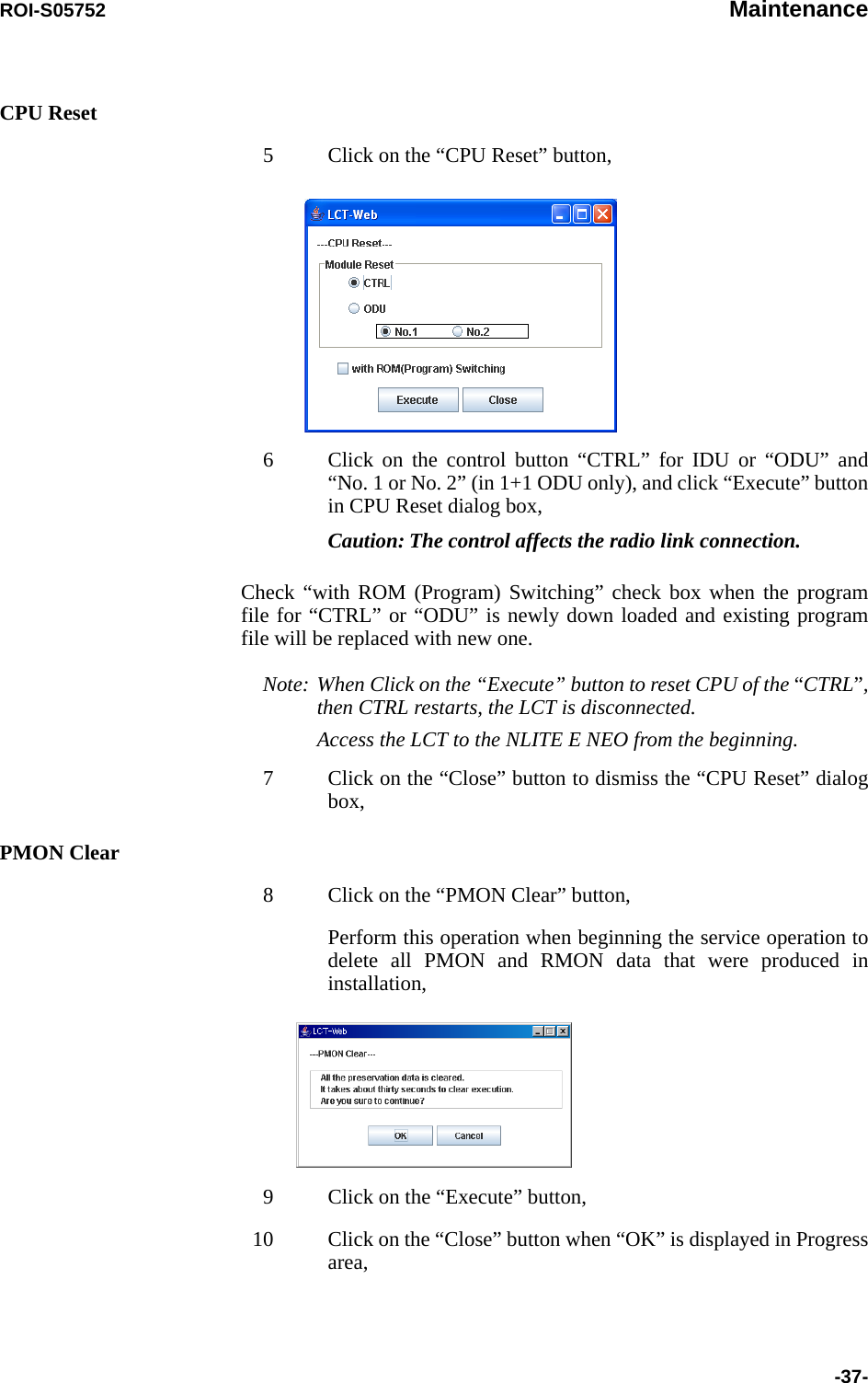
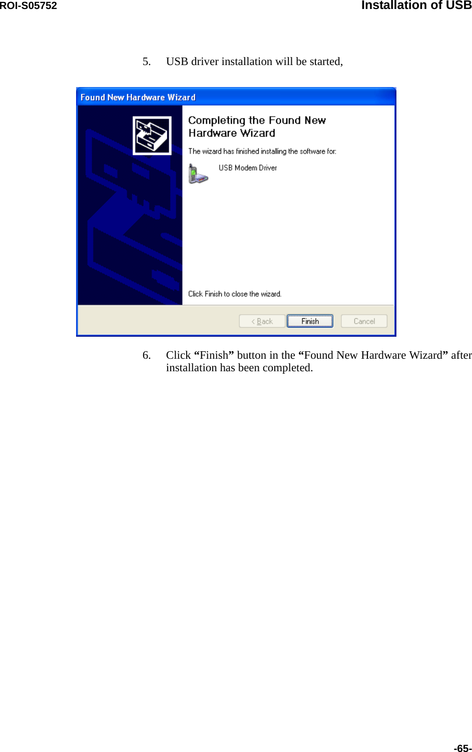
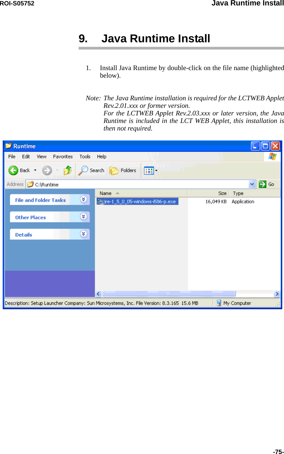
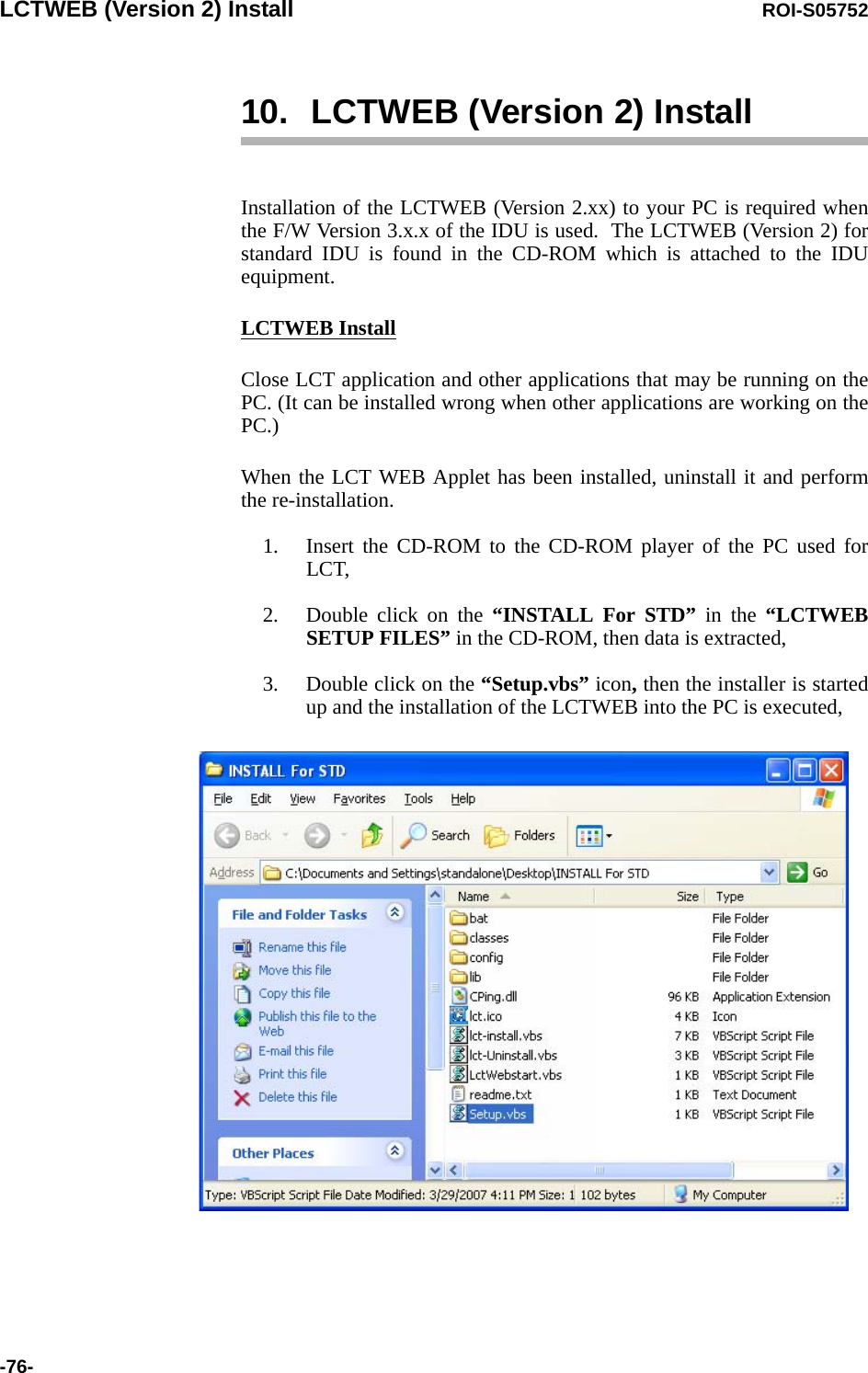
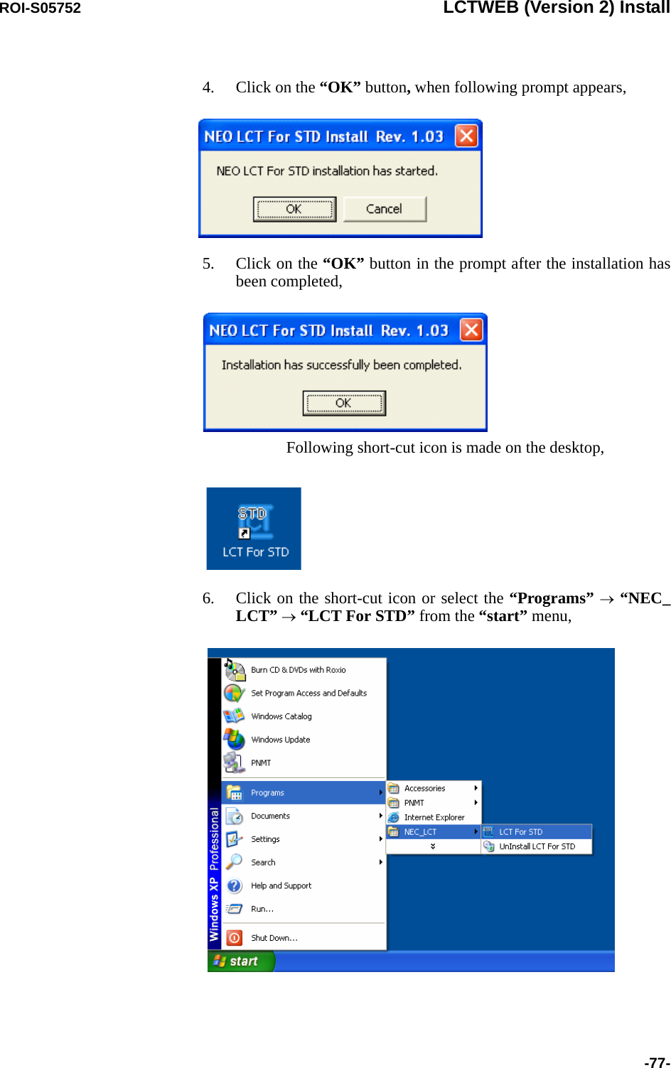
![ROI-S05752 Installation of USB-63-7. Installation of USBFollowing procedure explains how to install the USB modem driver to a windows XP PC.1. Connect the PC with a USB cable between the LCT port and the USB port,2. Select “Install from a list or specific location [Advanced]” and Click on the “Next” button,](https://usermanual.wiki/NEC-of-America/58155.User-Manual-Part-4/User-Guide-1070885-Page-83.png)
![Installation of USB ROI-S05752-64-3. Insert the CD-ROM of the USB driver to the PC and select “Search for the best driver in these locations” and check “Search removal media [floppy, CD-ROM...],” then, Click on the “Next”button, 4. Click “Continue Anyway” button in the Hardware Installation alert pop-up,](https://usermanual.wiki/NEC-of-America/58155.User-Manual-Part-4/User-Guide-1070885-Page-84.png)
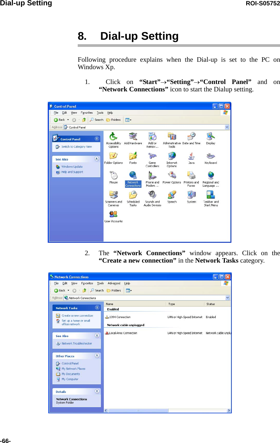
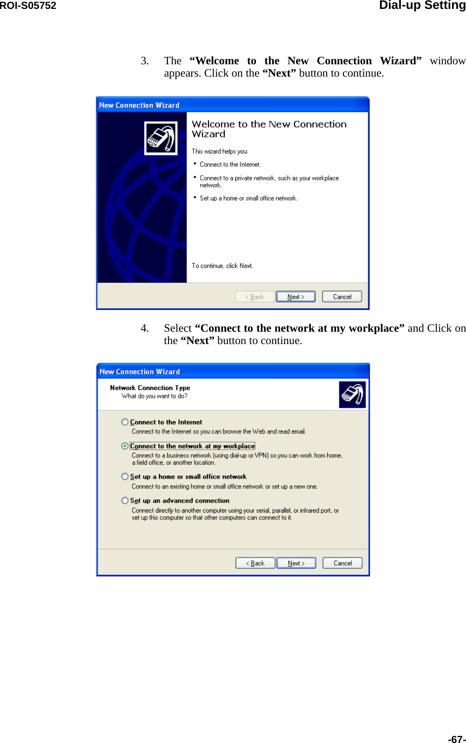
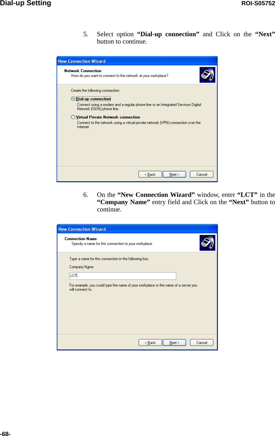
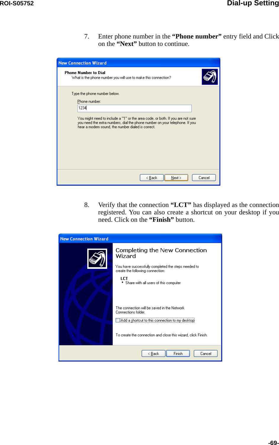
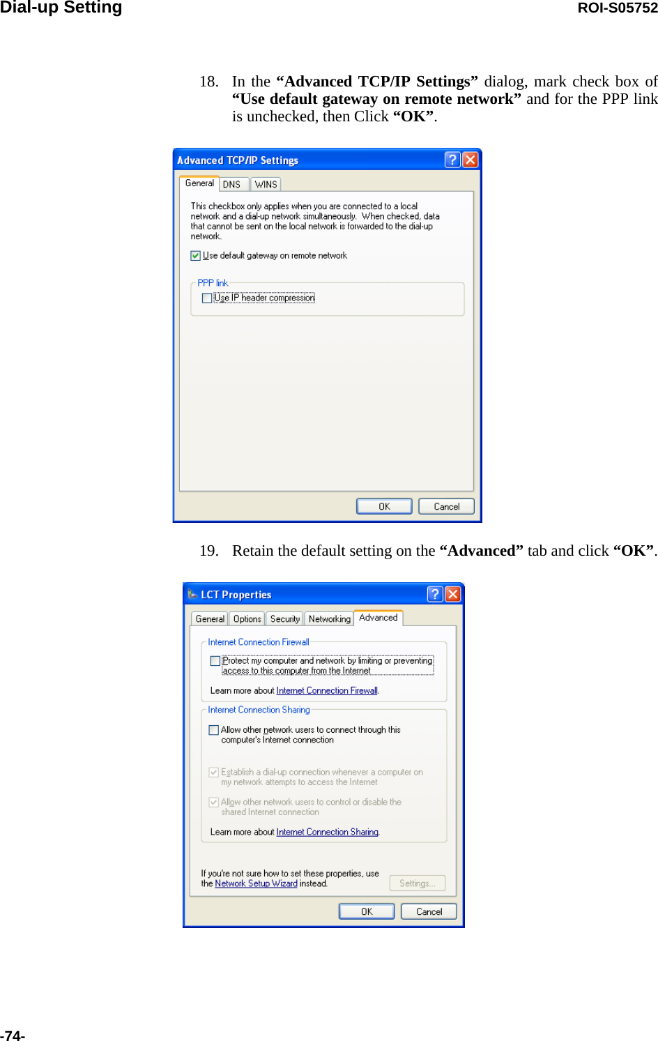
![Dial-up Setting ROI-S05752-70-9. On “Connect LCT” dialog, click “Properties”,10. Verify that “Modem-USB Modem Driver [COM(#)]” is displayed on the General dialog box connect using check box, and select “Show icon in notification area when connected” in the LCT Properties dialog. Then, Click on the “Configure” button.](https://usermanual.wiki/NEC-of-America/58155.User-Manual-Part-4/User-Guide-1070885-Page-90.png)
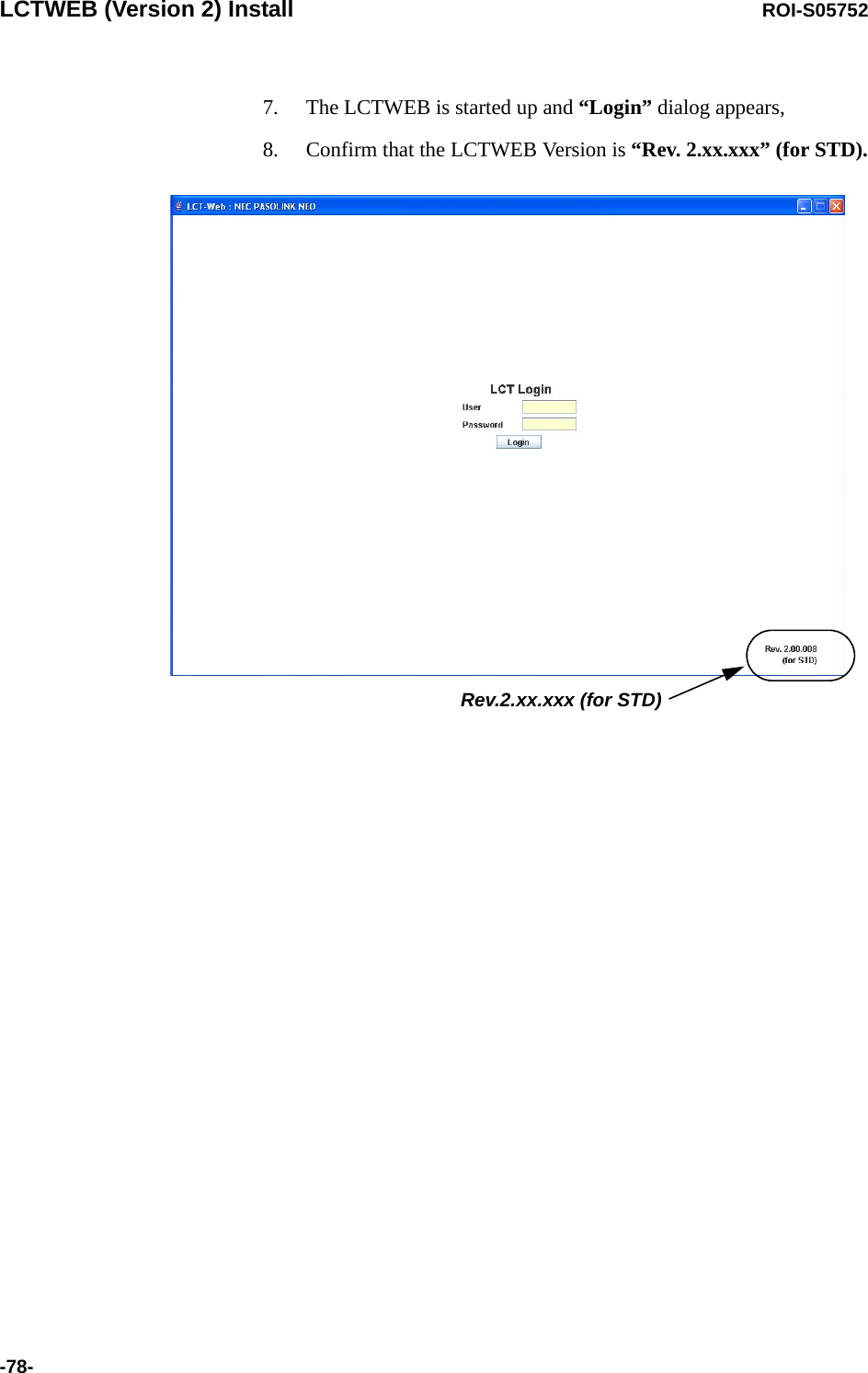
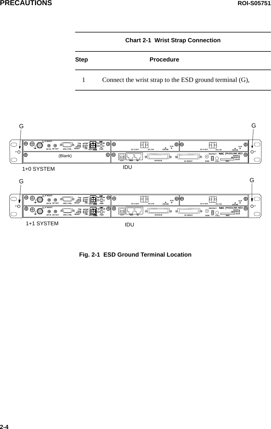


![ROI-S05751 PREVENTIVE MAINTENANCE4-14.SONET ROUTINE MAINTENANCEThis chapter provides the routine (annual) maintenance procedures to ensure the satisfactory operation of the equipment. During routinemaintenance, carefully observe the precautions given in Chapter 2.4.1 Meter Reading Chart 4-1 Meter ReadingStep ProcedureNotes:1. If an abnormal indication appears, check Alarm/Status, performance monitor and perform loopback test to distinguish sections of normal and alarmed.2. RX LEV varies depending on received RF signal level.3. Power Supply voltage at ODU varies depending on IF cable length between the IDU and ODU.4. During total number of erroneous bits and total number of correctly received bits are calculating, “Calculating” is displayed.5. 1.0E-10 is indicted equal to 1 x 10⁻¹⁰. ----Metering---No.1 No.2TX Power[dBm] +0.7 *RX Level[dBm] -65.2 -70.0Power Supply[V] -45 -45BER 1.0E-10 CalculatingLCT MENUAlarm/StatusEquipment SetupInventoryAUX I/OMaintenanceProvisioningMeteringPMON(History)For the LCT operation, refer to Chapter 6 of LCT Operation in Appendix of this Section IV.1 Connect the PC to the IDU using USB cable, (Refer to Fig. 2-2 in Chart 2-2)2 Login to the LCT with User name “User”,3 Click on “Metering” button in “LCT MENU”,](https://usermanual.wiki/NEC-of-America/58155.User-Manual-Part-4/User-Guide-1070885-Page-115.png)