NEC of America 58155 NEC NLite E 155 MB 5.8 GHz Digital Microwave Radio User Manual Part 5
NEC Corporation of America NEC NLite E 155 MB 5.8 GHz Digital Microwave Radio Part 5
Contents
- 1. User Manual Part 1
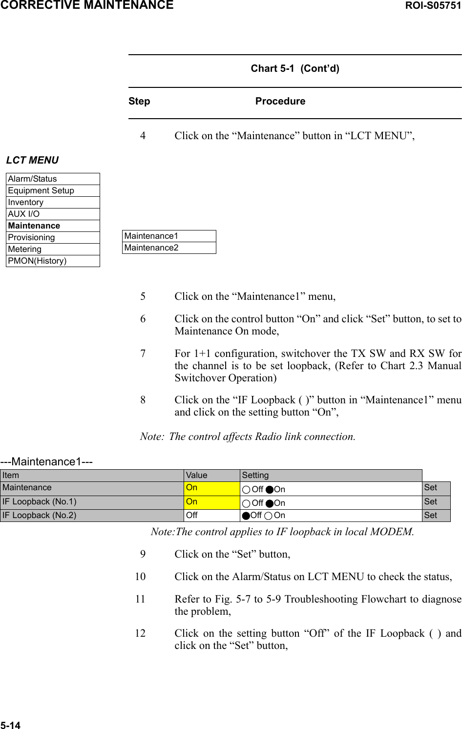
- 2. User Manual Part 2
- 3. User Manual Part 3
- 4. User Manual Part 4
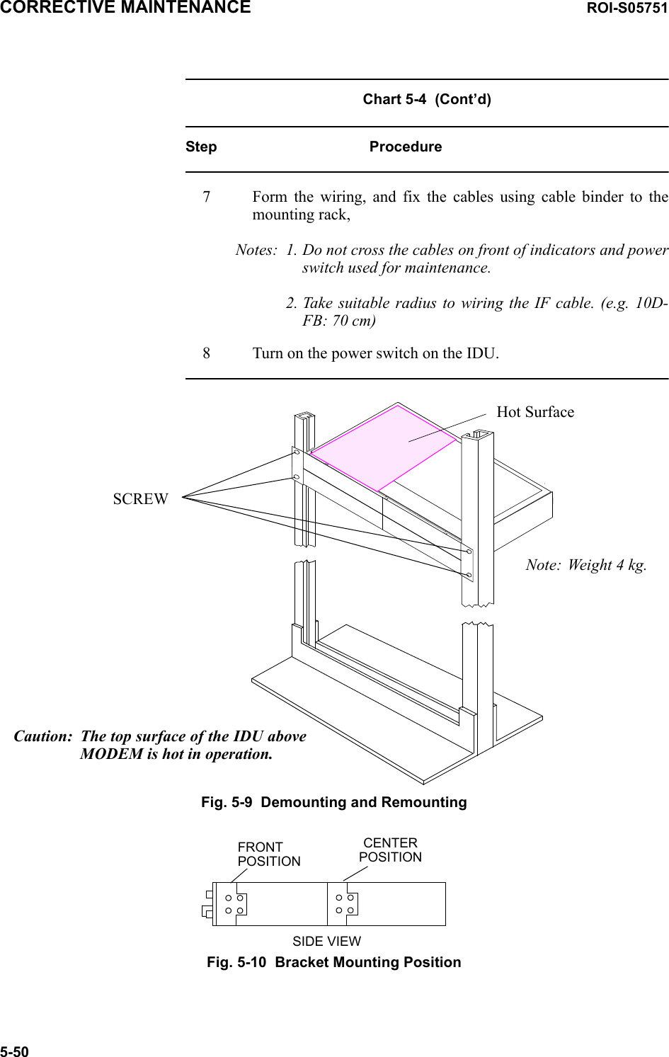
- 5. User Manual Part 5
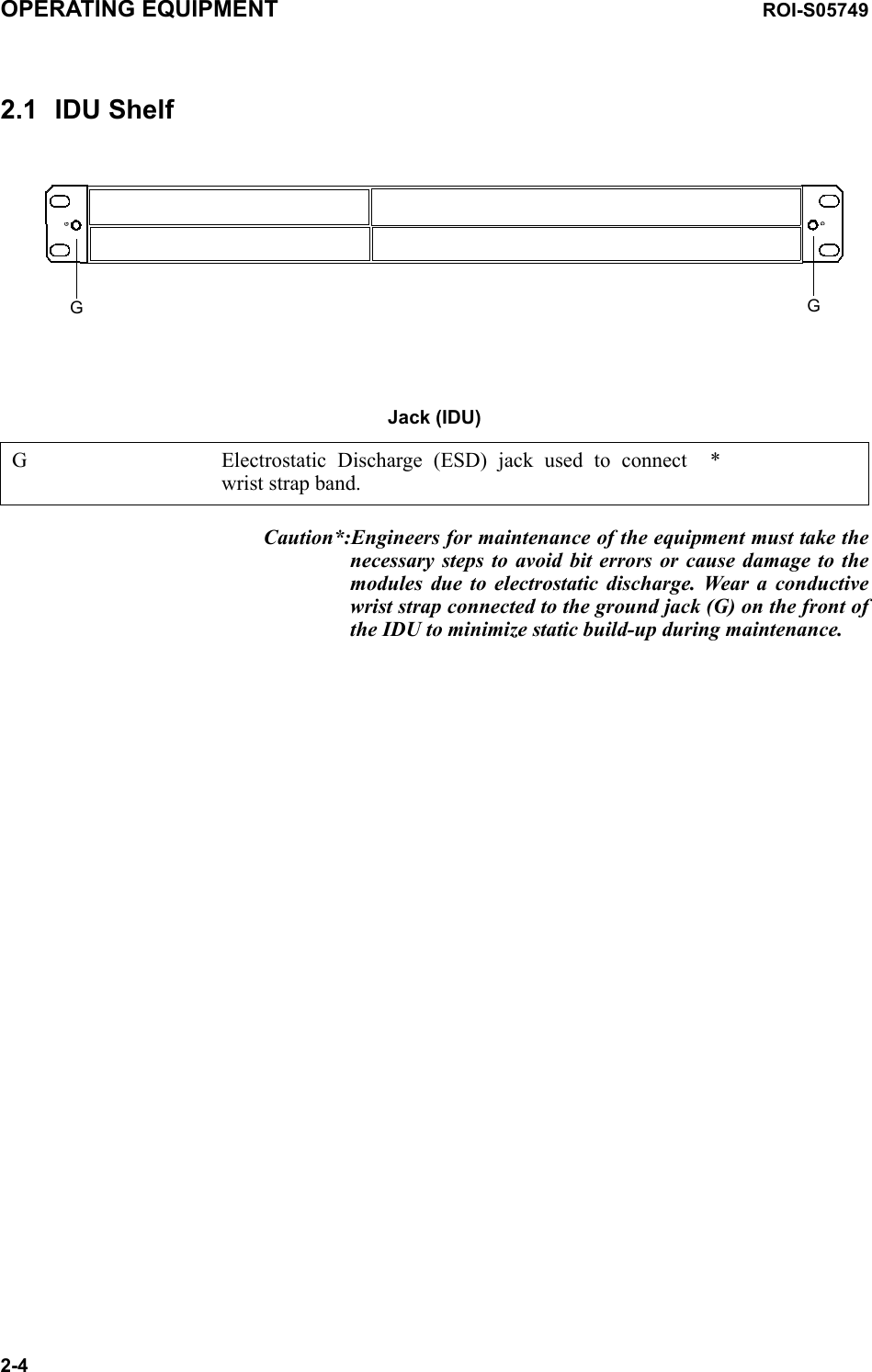
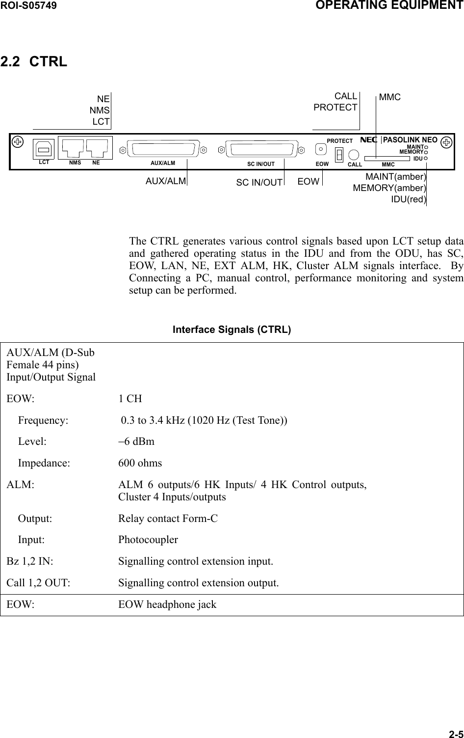
User Manual Part 5
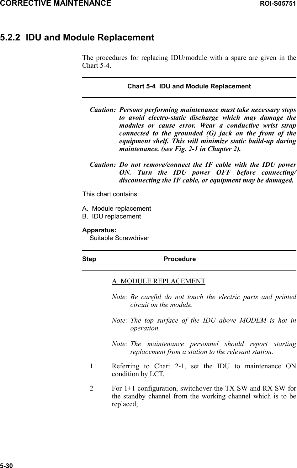
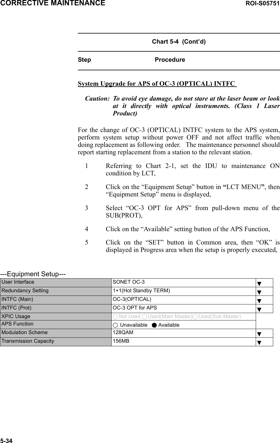


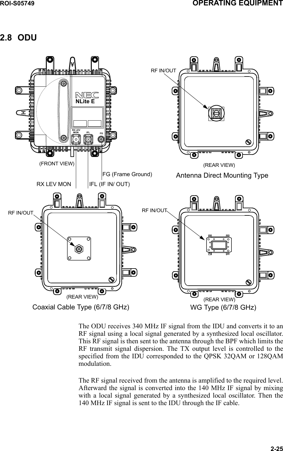
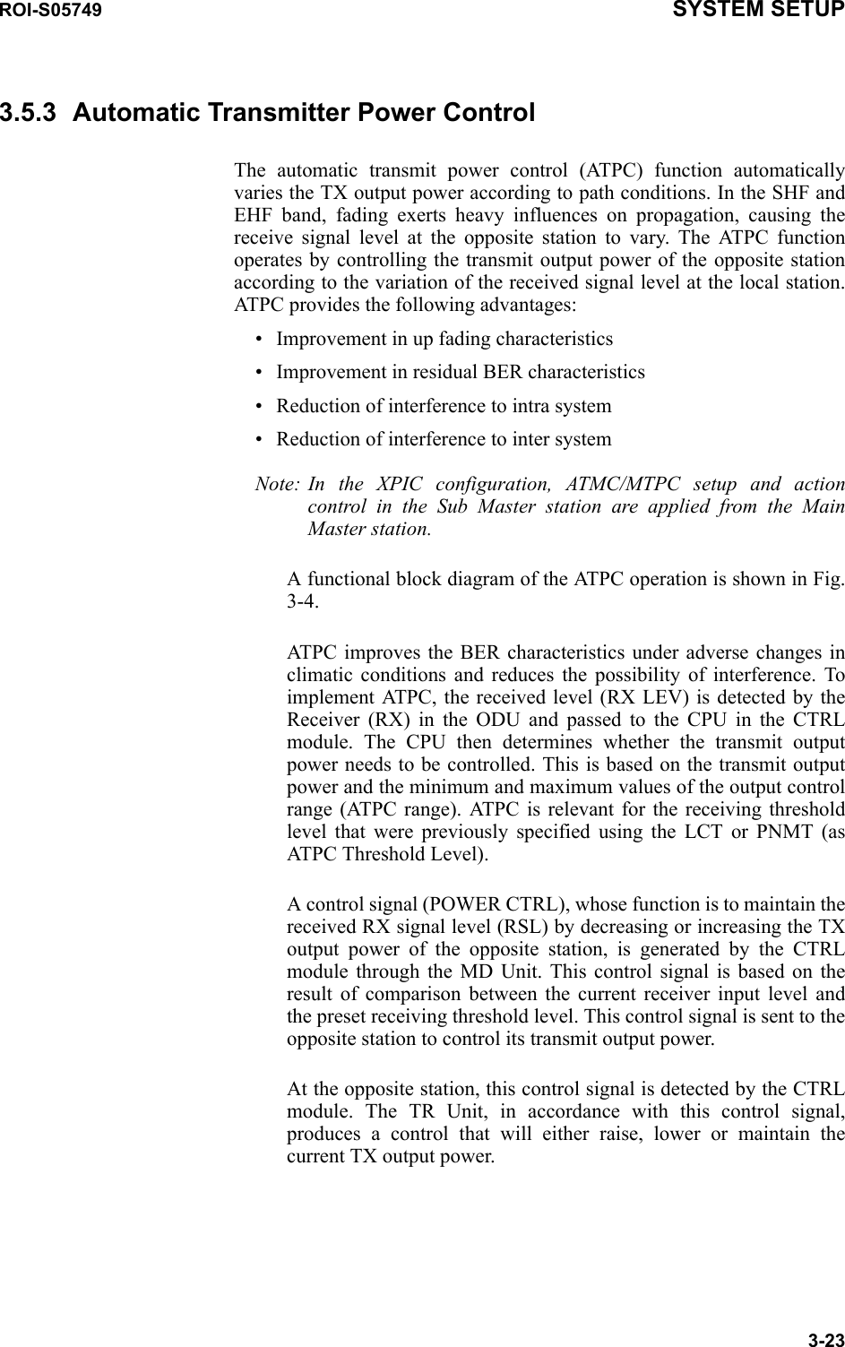
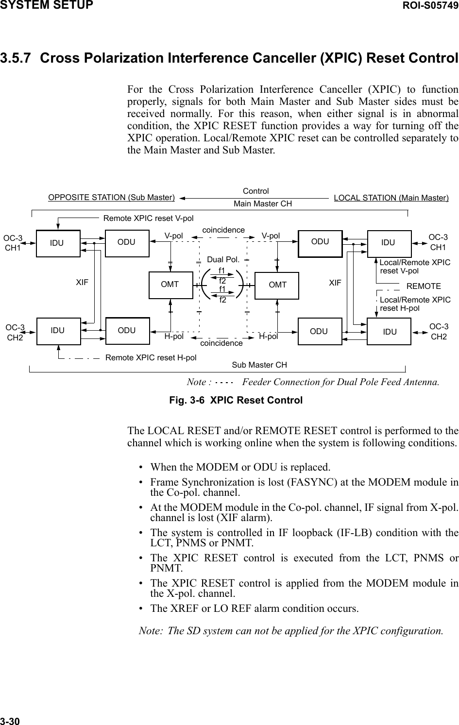
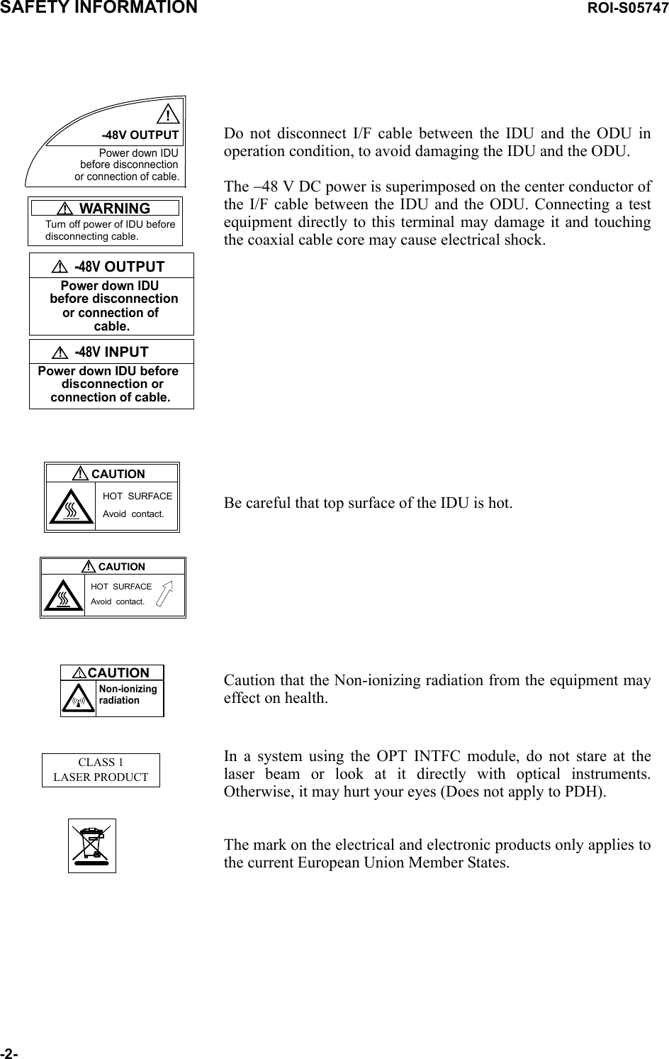
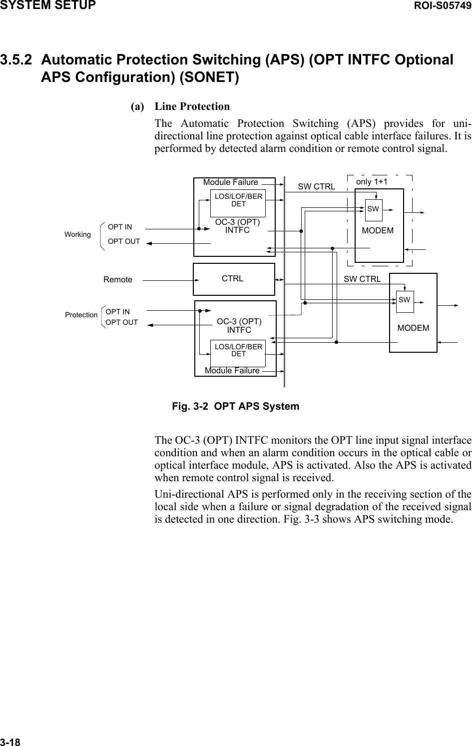
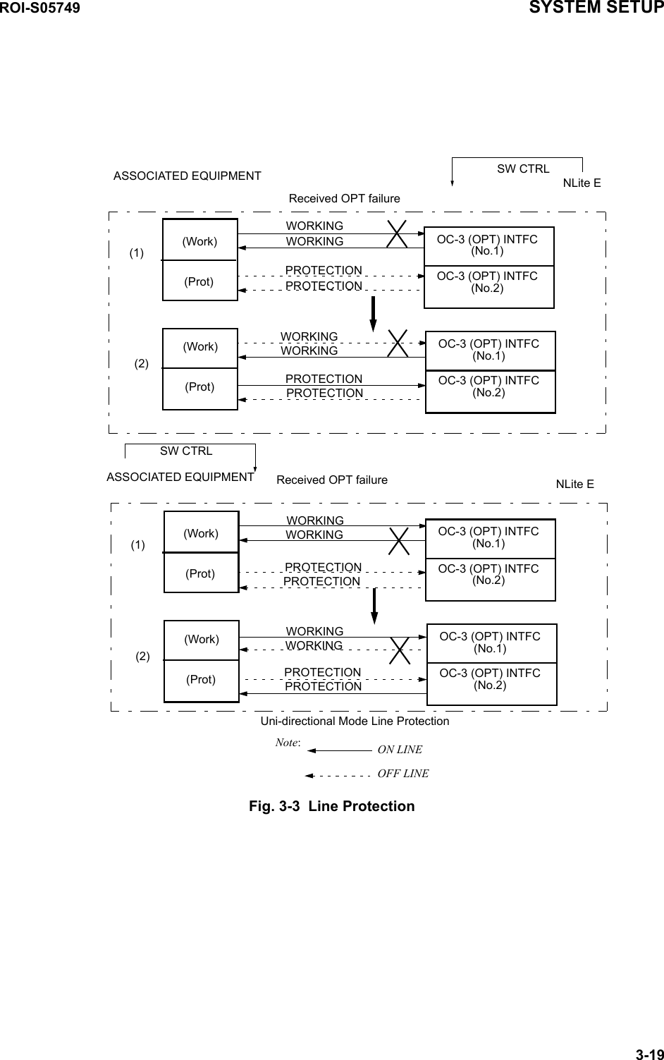
![SYSTEM SETUP ROI-S057493-2Equipment Setup for SONETUser Interface OC-3 GbE over OC-32Port LAN over OC-3Redundancy Setting 1+0(TERM)1+1(Hot Standby TERM)1+1(Twinpath TERM)INTFC Main (WORK) OC-3(Optical)OC-3(Electrical) GbE over OC-3 When the “SONET GbE over OC-3” is selected for User Interface.2Port LAN over OC-3INTFC SUB (PROT) Not UsedOC-3 (Optical)WSWS/LANXPIC Usage Not UsedUsed (Main Master)Used (SUB Master)APS Function UnavailableAvailableModulation Scheme 128QAM (fixed)Transmission Capacity 156MB (fixed)TX RF Frequency(No.1) [MHz] TX RF Frequency(No.2) [MHz] RX RF Frequency(No.1) [MHz] RX RF Frequency(No.2) [MHz] Frame ID(No.1) (Up to #32)Frame ID(No.2) (Up to #32)TX Power Control MTPCATPCLAN Port Usage (Main) USED (fixed when GbE INTFC is applied.)LAN Capacity(Main) 150Mbps (fixed when GbE INTFC is applied.)LAN Port Usage (Main) P1=75MB/P2=75MB (selectable when LAN INTFC is applied.)P1=100MB/P2=50MBBest EffortP1=100MB/P2=Not UsedLAN Capacity(Main) 150Mbps (fixed when LAN INTFC is applied.)LAN Port Usage (SUB) P1-2 Shared/1Port Only(WS)P1-2 Shared/1Port Only(SC)LAN Capacity(SUB) 64kbps128kbps192kbps256kbps2Mbps](https://usermanual.wiki/NEC-of-America/58155.User-Manual-Part-5/User-Guide-1070886-Page-88.png)
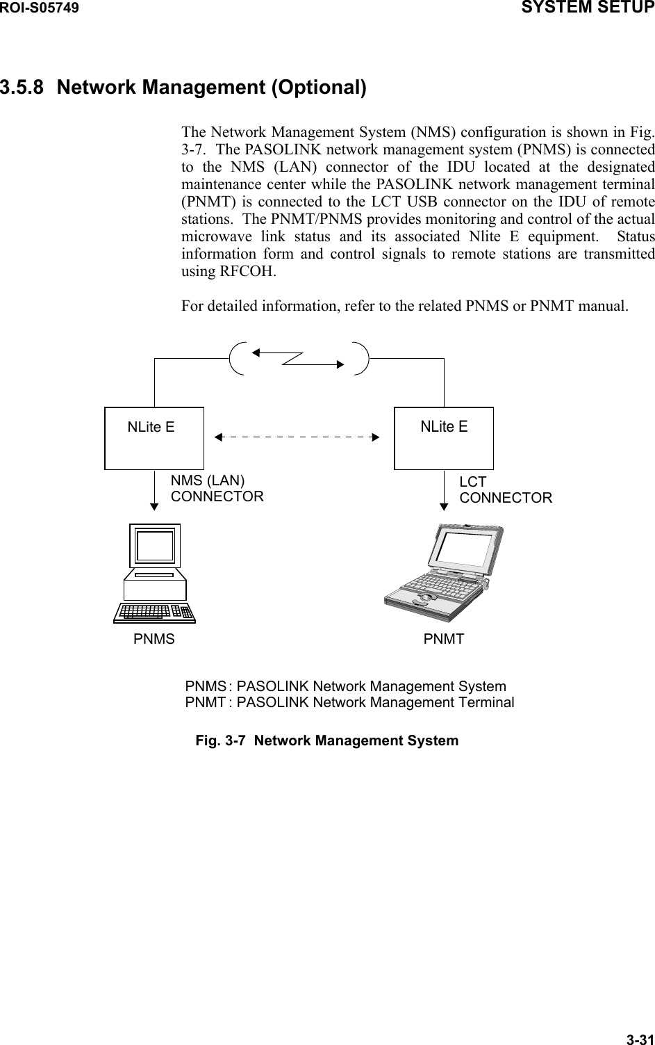
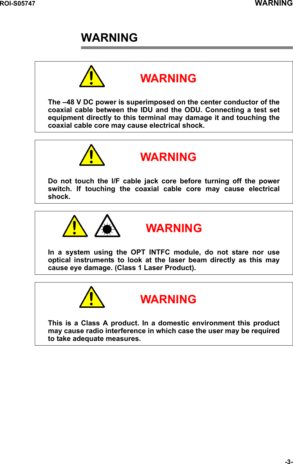
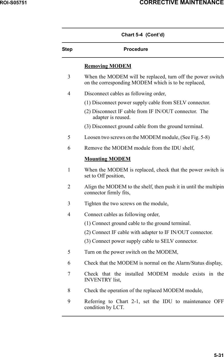
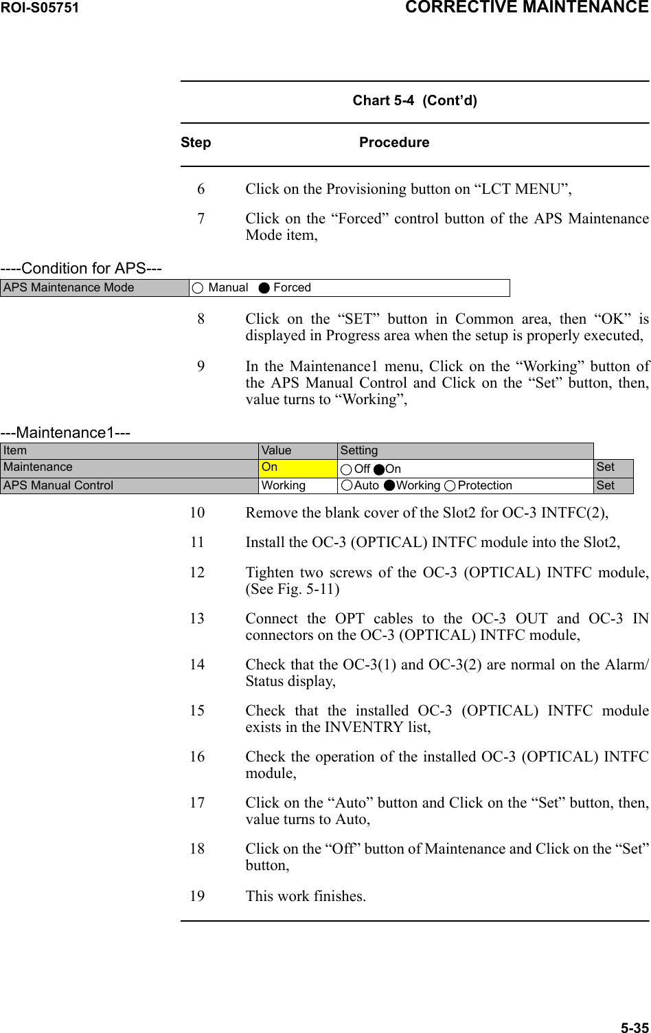
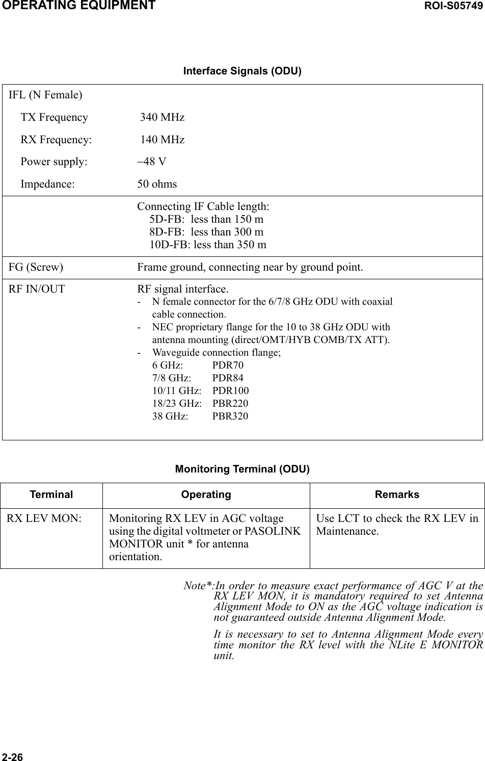
![ROI-S05749 SYSTEM SETUP3-3---ODU FREQ INF---TX Start Frequency(No.1) [MHz]TX Stop Frequency(No.1) [MHz]Frequency Step(No.1) [MHz]Shift Frequency(No.1) [MHz]Upper/Lower(No.1)Sub Band(No.1)TX Start Frequency(No.2) [MHz]TX Stop Frequency(No.2) [MHz]Frequency Step(No.2) [MHz]Shift Frequency(No.2) [MHz]Upper/Lower(No.2)Sub Band(No.2)Equipment Setup for SONET](https://usermanual.wiki/NEC-of-America/58155.User-Manual-Part-5/User-Guide-1070886-Page-89.png)
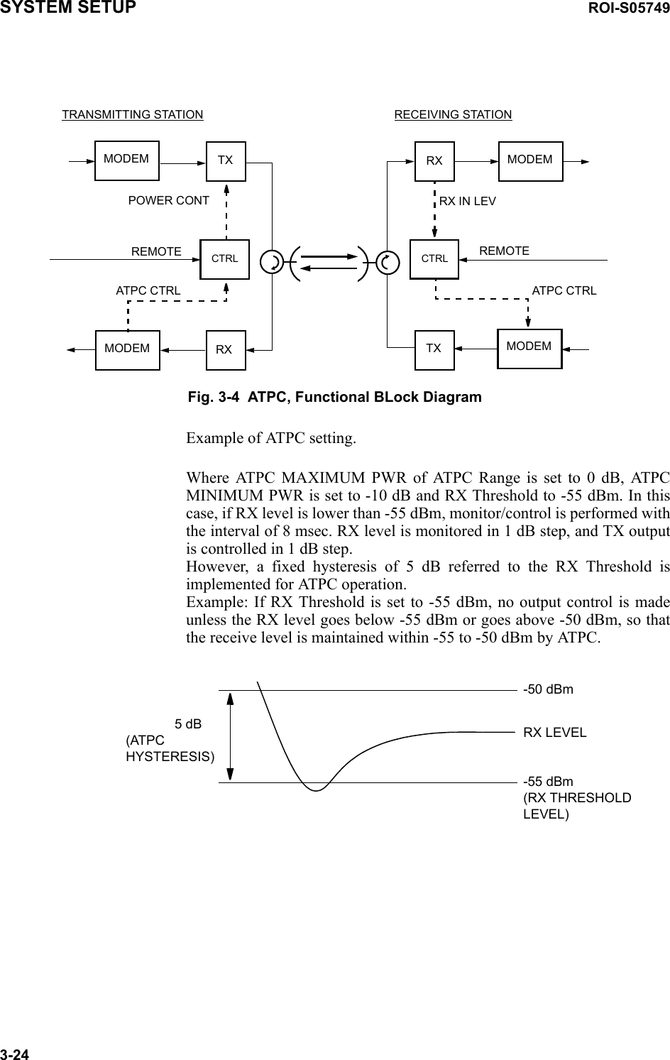
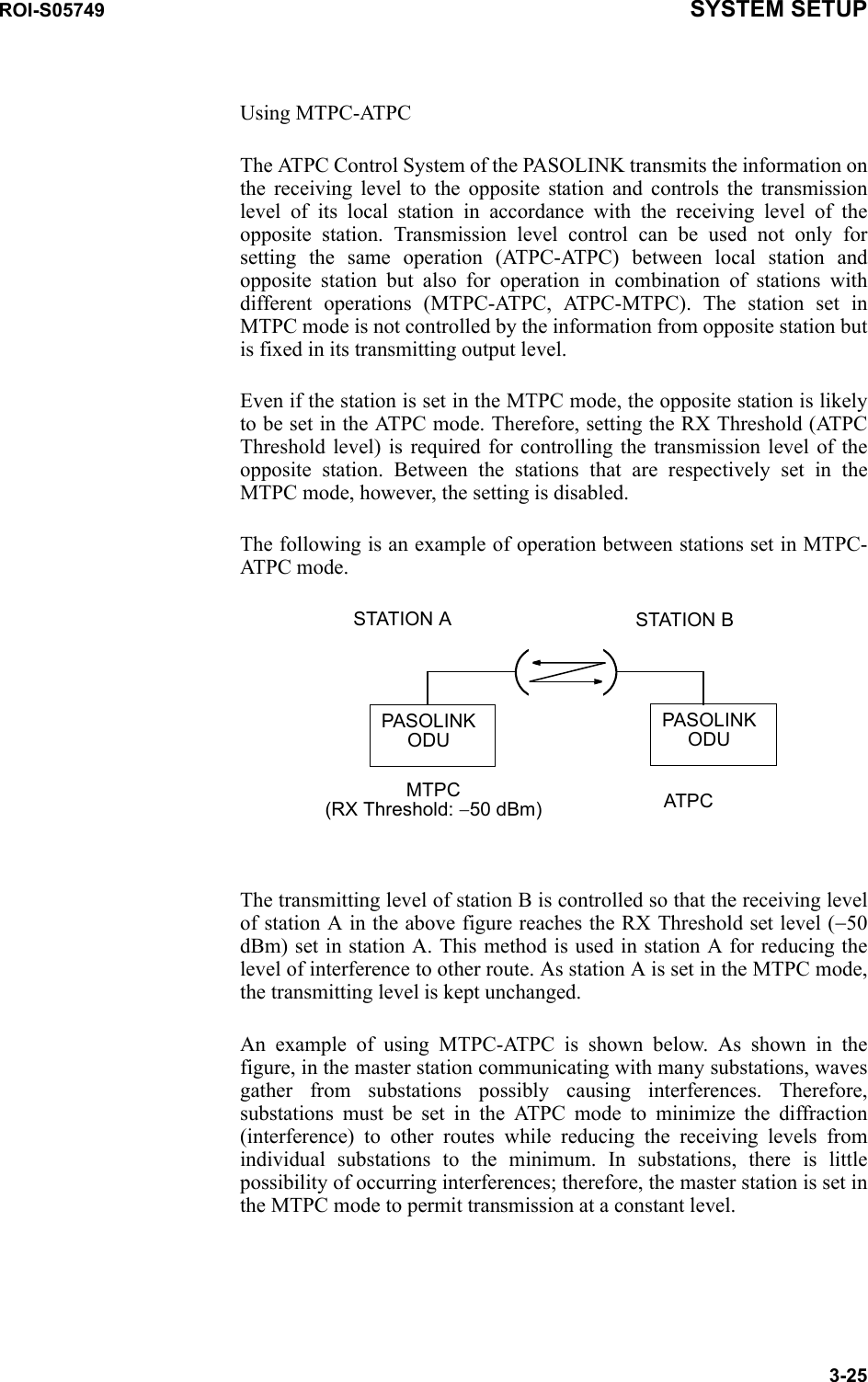
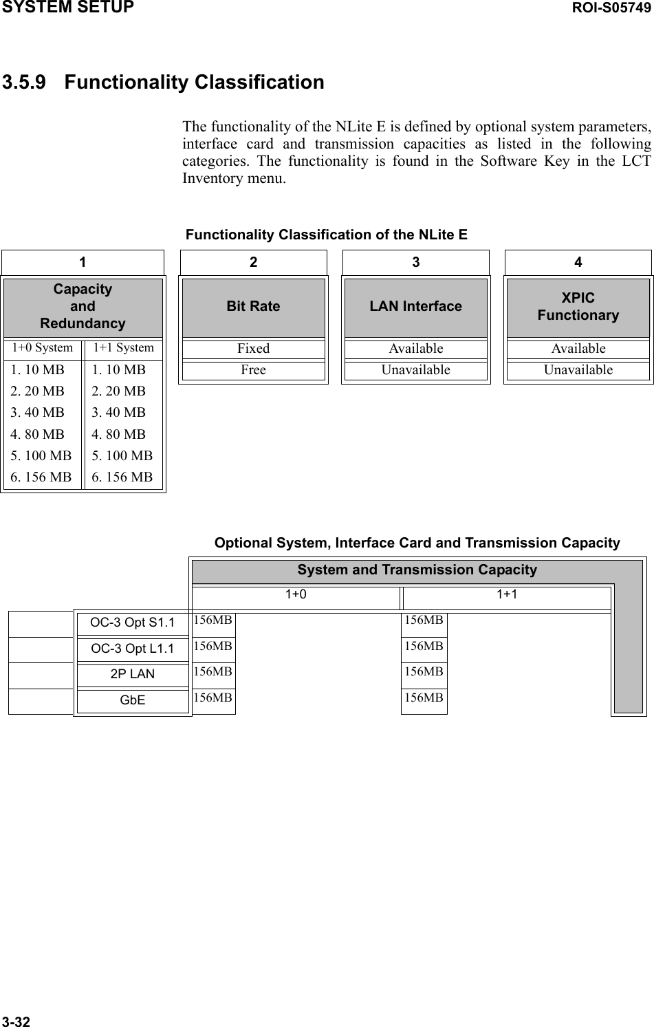
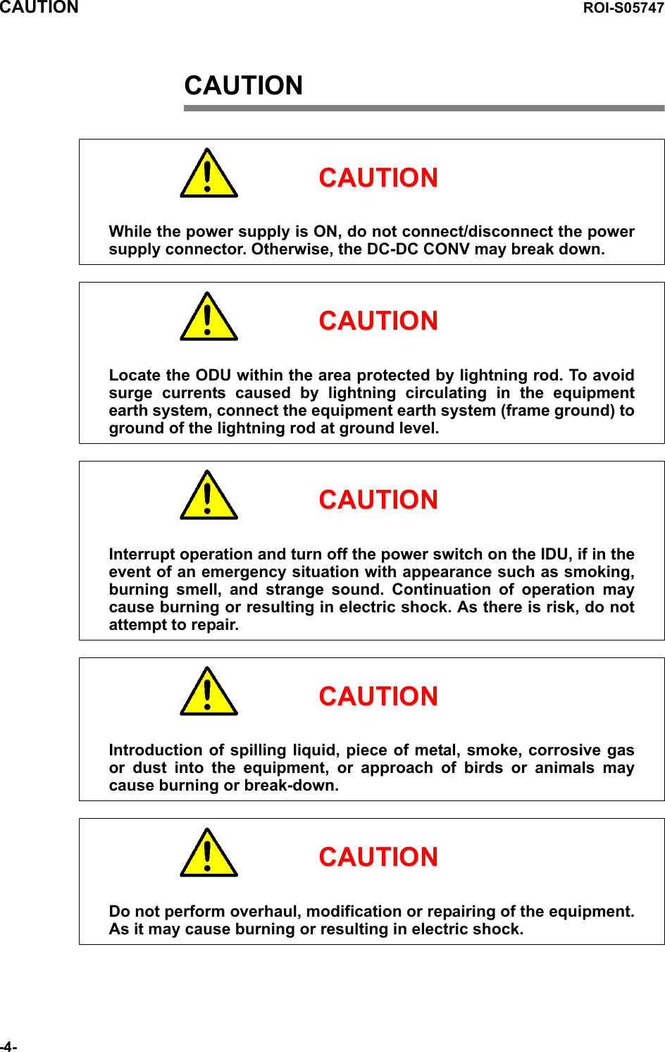
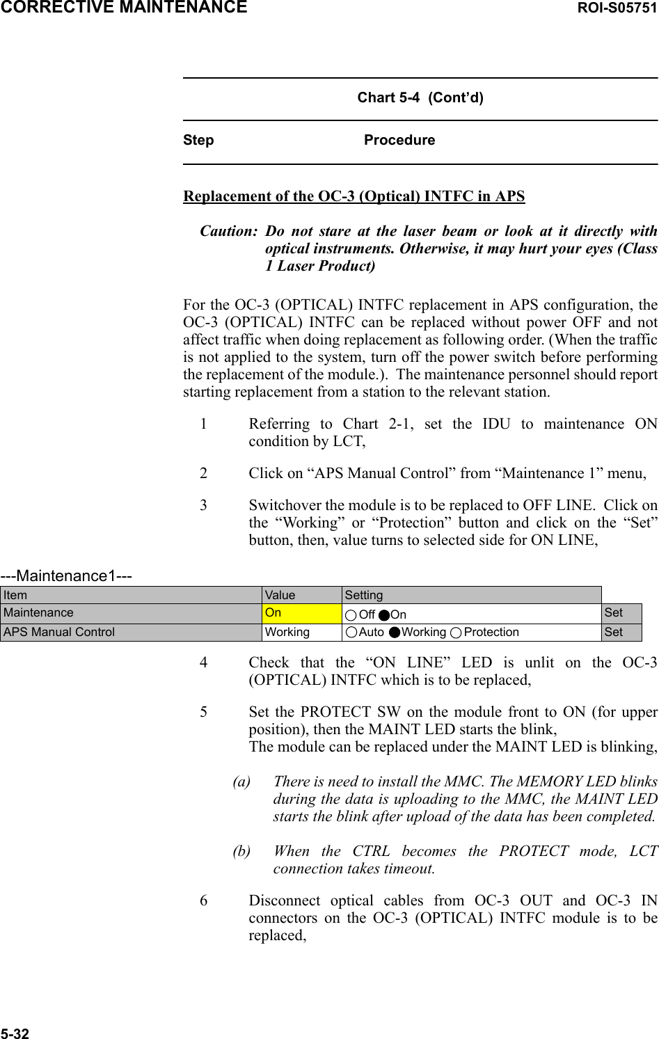
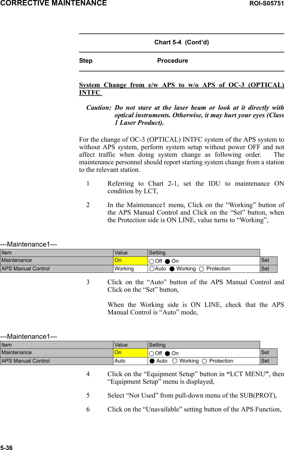
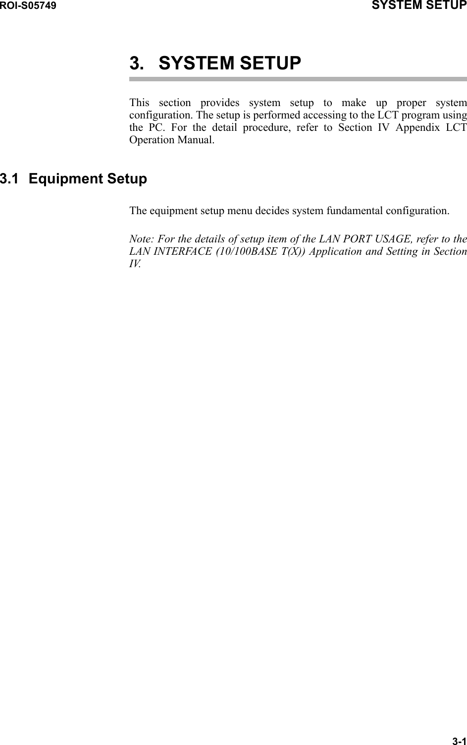
![SYSTEM SETUP ROI-S057493-6OC-3 Setting MS-AIS Generation Disabled EnabledALS ALS Function Disabled EnabledALS Interval 60sec 180sec 300secTX Power Control ATPC Threshold Level(No.1/2) [dBm] Additional ATT(No.1/2 [dB] ATPC Range(MAX)(No.1/2) [dB] ATPC Range(MIN)(No.1/2) [dB] ATPC Power Mode(No.1/2) HOLD Max MINMTPC TX Power (No.1/2) [dBm] ATPC Threshold Level(No.1/2) [dBm] Additional ATT(No.1/2) [dB]Condition for TX/RX SW TX SW Priority RX SW Priority RX SW Maintenance Mode RX SW Condition-Early WarningNon-Priority Priority No.1 Non-Priority Priority No.1 Manual Forced Included EW Excluded EWCondition for APS APS Maintenance ModeAPS Condition-SF(PROT) APS Condition-Signal Degrade-SD(B1) Lock in UsageLock in Count [times] Lock in Detect Time [min] Lock in Hold Time [hours]Manual Forced Priority High Priority Low Included SD Excluded SD Not Used UsedRelay Setting ALM output for RL1 to RL6 HK output for RL3 to RL6 Cluster1 to Cluster4 inputCluster1 to Cluster4 outputOut HK Disabled Enabled OutTCN Threshold(15min) DMR/ OCR/RCVR MUX OCR/RCVROFS UAS ES SES BBE SEPTCN Threshold(1day) DMR/ OCR/RCVR MUX OCR/RCVROFS UAS ES SES BBE SEPPMON Select RX Level TCN Threshold [dBm] SES Activation Condition 30[%] 15[%]Others EOW2 External SettingAlarm Correlation CapacityNormal Invert Off On](https://usermanual.wiki/NEC-of-America/58155.User-Manual-Part-5/User-Guide-1070886-Page-92.png)
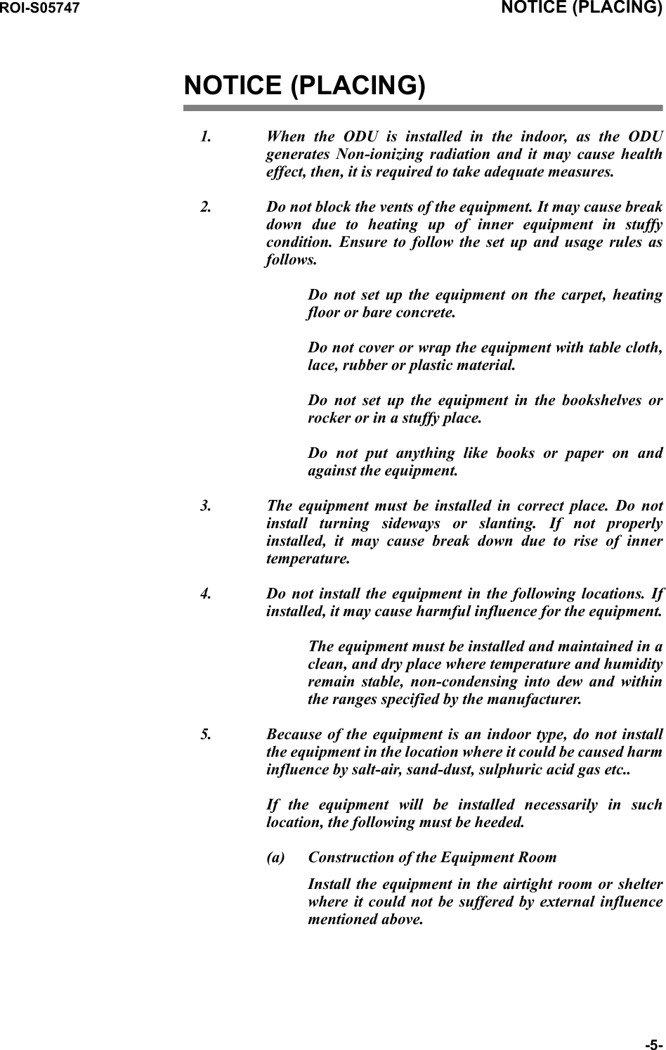
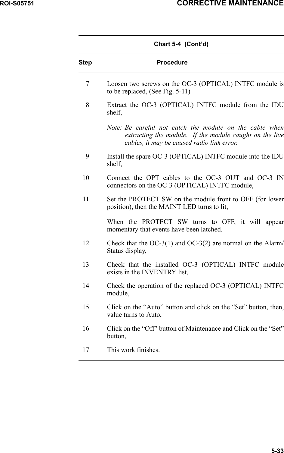
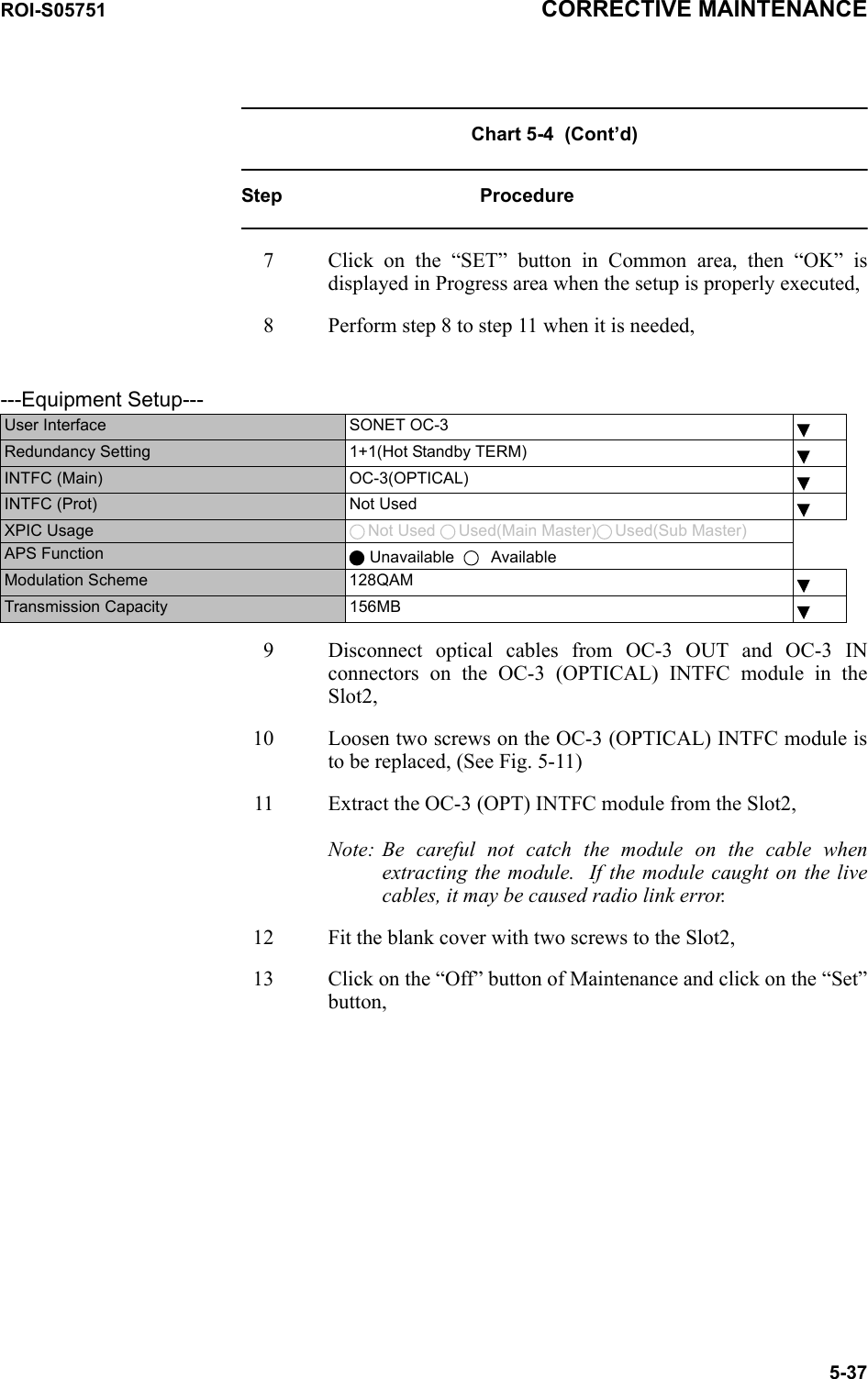
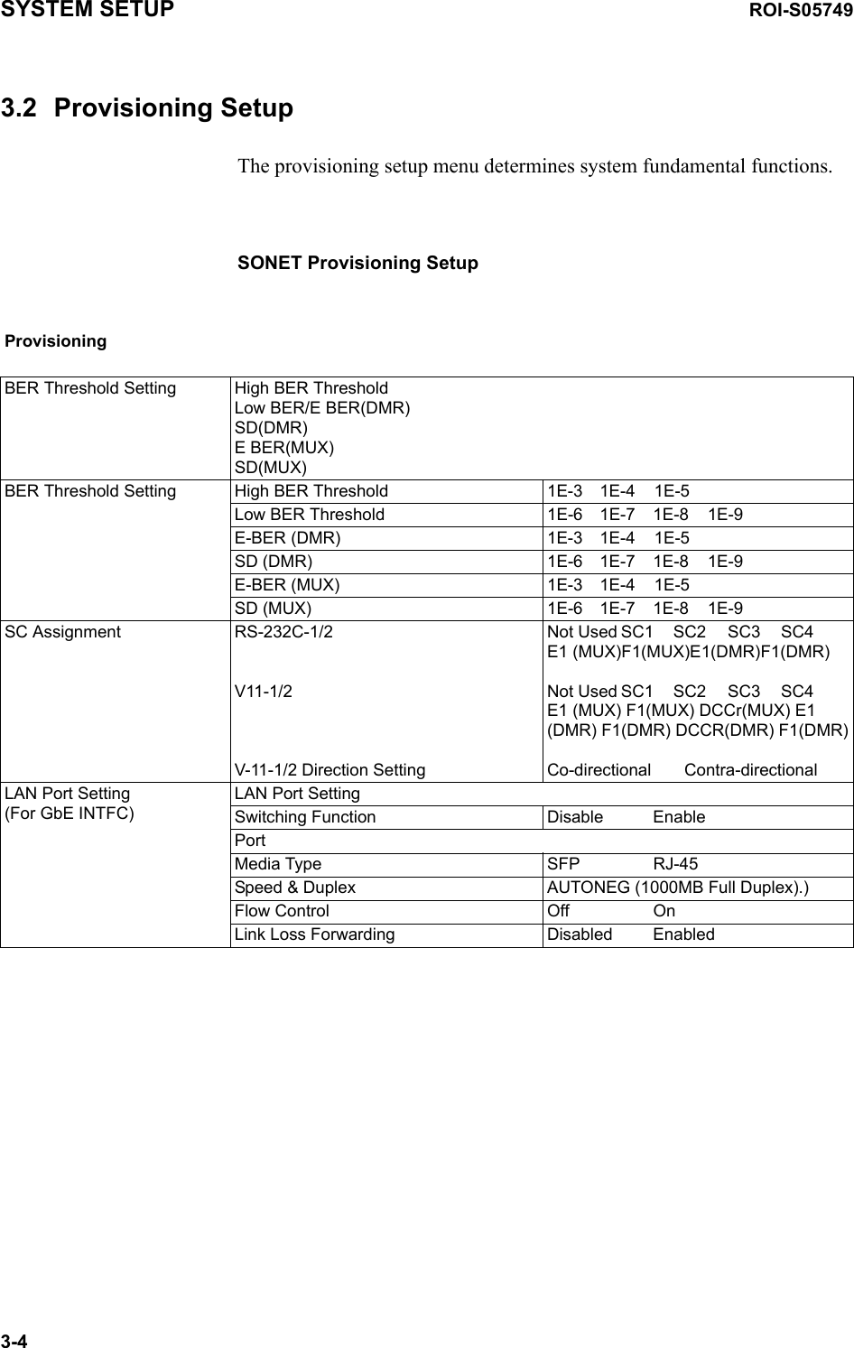
![ROI-S05749 SYSTEM SETUP3-21 • APS Maintenance ModeThis is a setup to give priority to manual control operation in maintenance.Manual: Give priority to alarm events in maintenance operation. In this mode, manual control disables the operation under alarm condition.Forced: Give priority to forced control in maintenance operation. In this mode, manual control enables the operation under alarm condition and the alarmed side can be selected.Caution: When the APS Maintenance Mode is set to “Forced” in provisioning, APS manual control can select either Working or Protection line though one is alarmed. Then, take care switching to avoid traffic interruption.• APS Condition-SF(PROT):This is a setup to give higher priority to switchover by SF in Protection side.Priority High: This setup gives highly priority to SF of Protection side (installed in INTFC Slot2) for switchover control condition. Since the setup gives priority higher than the Forced Control, the ONLINE is maintained in Main side (installed in INTFC Slot1) under occurrence of SF condition of Protection side. LCT MENUAlarm/StatusEquipment SetupInventoryAUX I/OMaintenanceProvisioningBER Threshold SettingSC AssignmentOC-3 SettingTX Power ControlCondition for TX/RX SWCondition for APSRelay SettingTCN Threshold (15min)TCN Threshold (1day)PMON SelectOthersMeteringPMON(Current)PMON(History) ---Condition for APS--- RangeAPS Maintenance Mode Manual ForcedAPS Condition-SF(PROT) Priority High Priority LowAPS Condition-SD(B1) Included SD Excluded SDLock in Usage Not Used UsedLock in Detect Count [times] 4 1 to 255Lock in Detect Time [min] 10 1 to 60Lock in Hold Time [hours]) 24 1 to 48](https://usermanual.wiki/NEC-of-America/58155.User-Manual-Part-5/User-Guide-1070886-Page-107.png)