NXP Austria CLEV6630B Customer Evaluation Board CLEV6630B User Manual Integration Manual EXPLORE NFC
NXP Austria GmbH Customer Evaluation Board CLEV6630B Integration Manual EXPLORE NFC
UserManual.wiki
>
NXP Austria
>
CLEV6630B User Manual
>
Integration Manual
Contents
1.
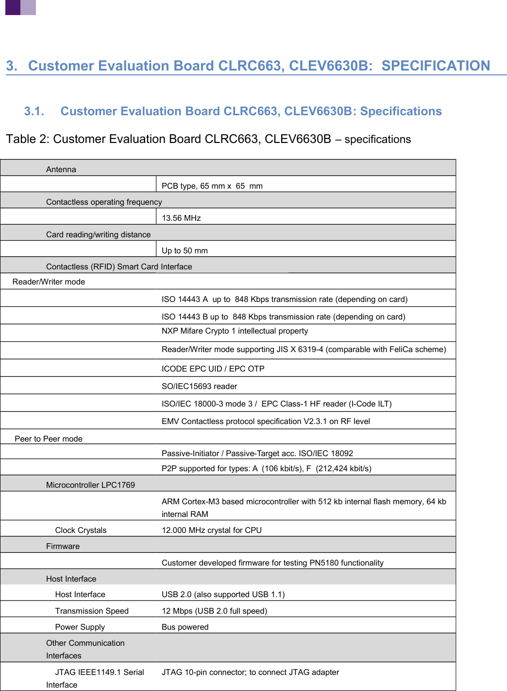
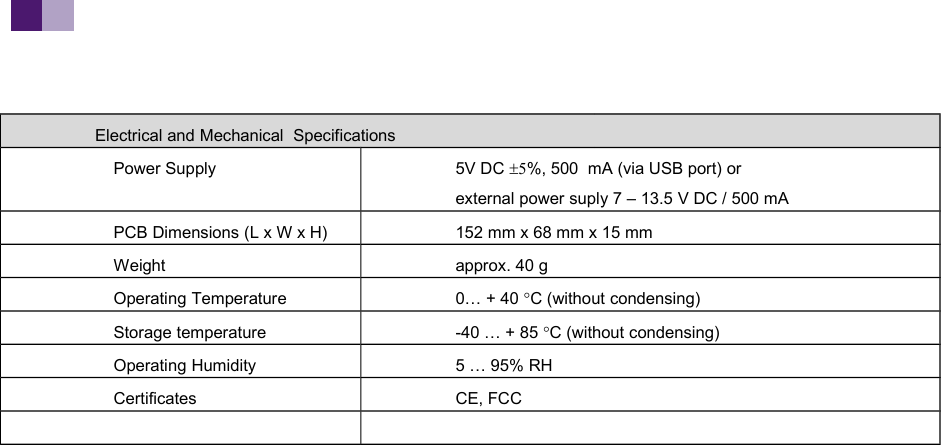
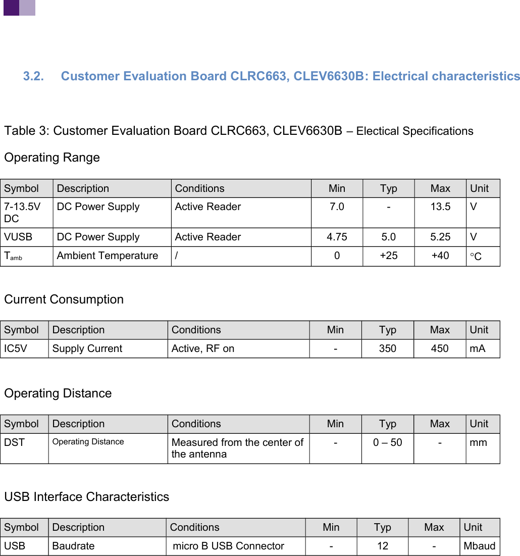
HW manual
2.
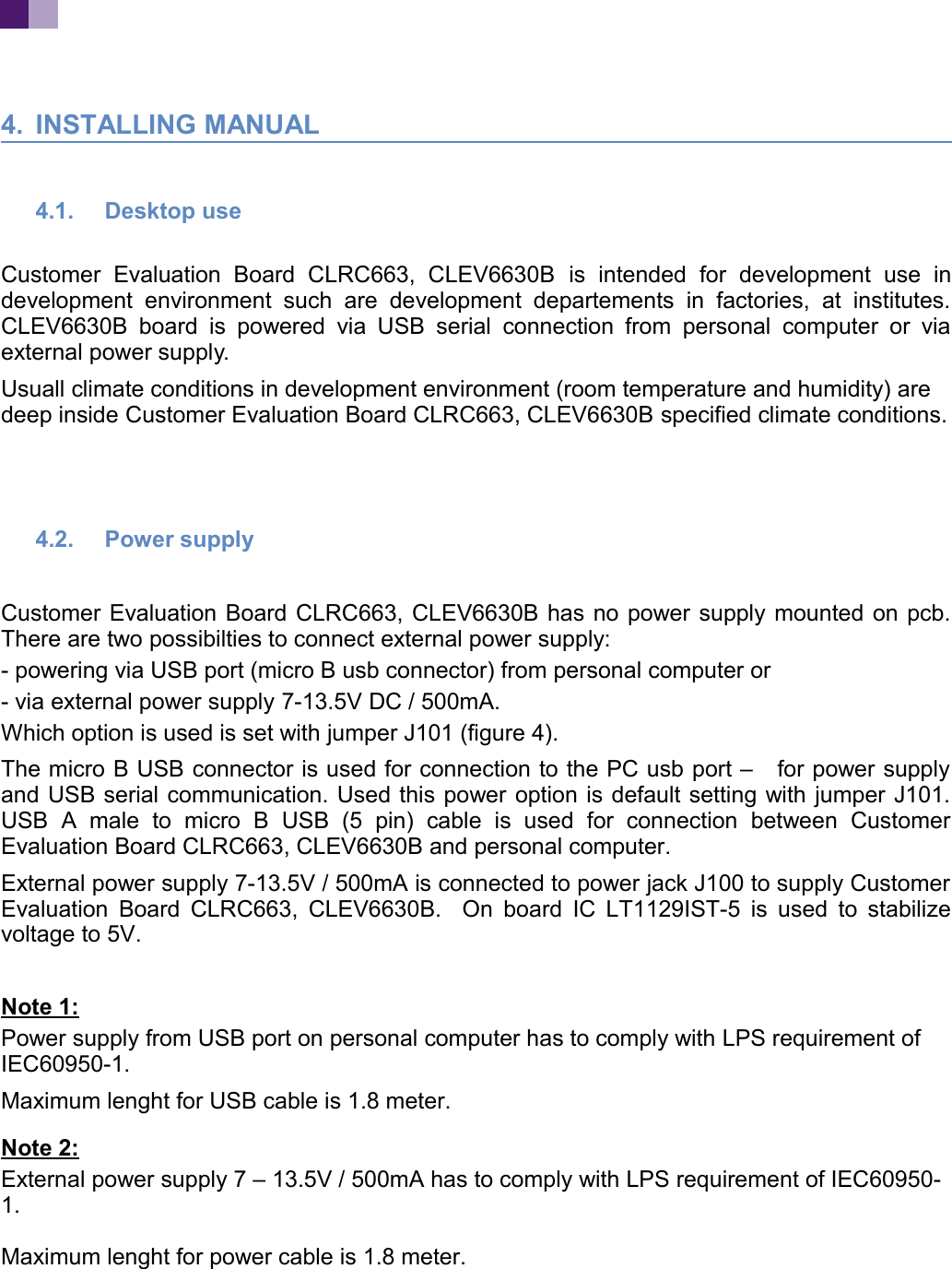
Integration Manual
Integration Manual
Navigation menu
Upload a User Manual
Namespaces
Wiki Guide
HTML
PDF
Info
Views
User Manual
Discussion / Help
Navigation