Nanotron Technologies NANONET-TRX nanoNET TRX 2.4 GHz CSS Transceiver User Manual UserMan
Nanotron Technologies GmbH nanoNET TRX 2.4 GHz CSS Transceiver UserMan
UserManual.wiki
>
Nanotron Technologies
>
NANONET TRX User Manual
UserMan
Navigation menu
Upload a User Manual
Namespaces
Wiki Guide
HTML
PDF
Info
Views
User Manual
Discussion / Help
Navigation


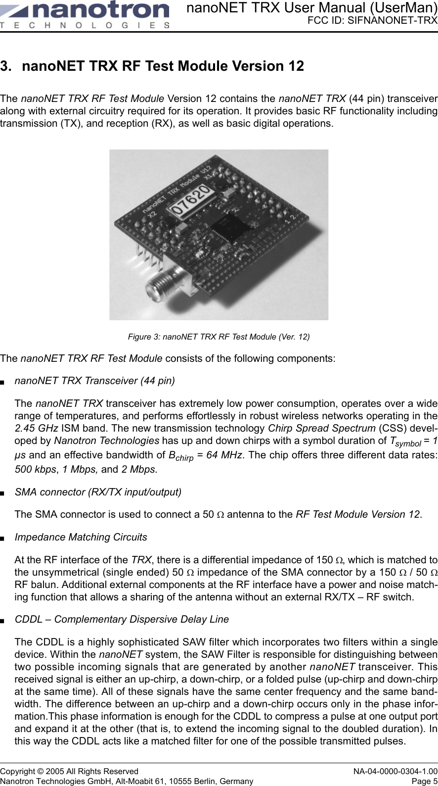

![nanoNET TRX User Manual (UserMan)FCC ID: SIFNANONET-TRXNA-04-0000-0304-1.00 Copyright © 2005 All Rights ReservedPage 22 Nanotron Technologies GmbH, Alt-Moabit 61, 10555 Berlin, Germany7.1. Vertical Diagram for Model 17010.11The following shows the vertical diagram for the antenna model 17010.11 measured at 2.40 GHz, 2.45 GHz, and 2.50 GHzFigure 23: Vertical Diagram for Antenna model 17010.11Beam Peak ValuesNull Depth ValuesFrequency [dB] at [deg]2.40 GHz -0.61 -99.942,45 GHz -0.74 81.952,50 GHz -0.64 67.96Frequency [dB] at [deg]2.40 GHz -38.47 -4.002,45 GHz -53.94 -2.002,50 GHz -41.44 177.90](https://usermanual.wiki/Nanotron-Technologies/NANONET-TRX/User-Guide-510418-Page-28.png)
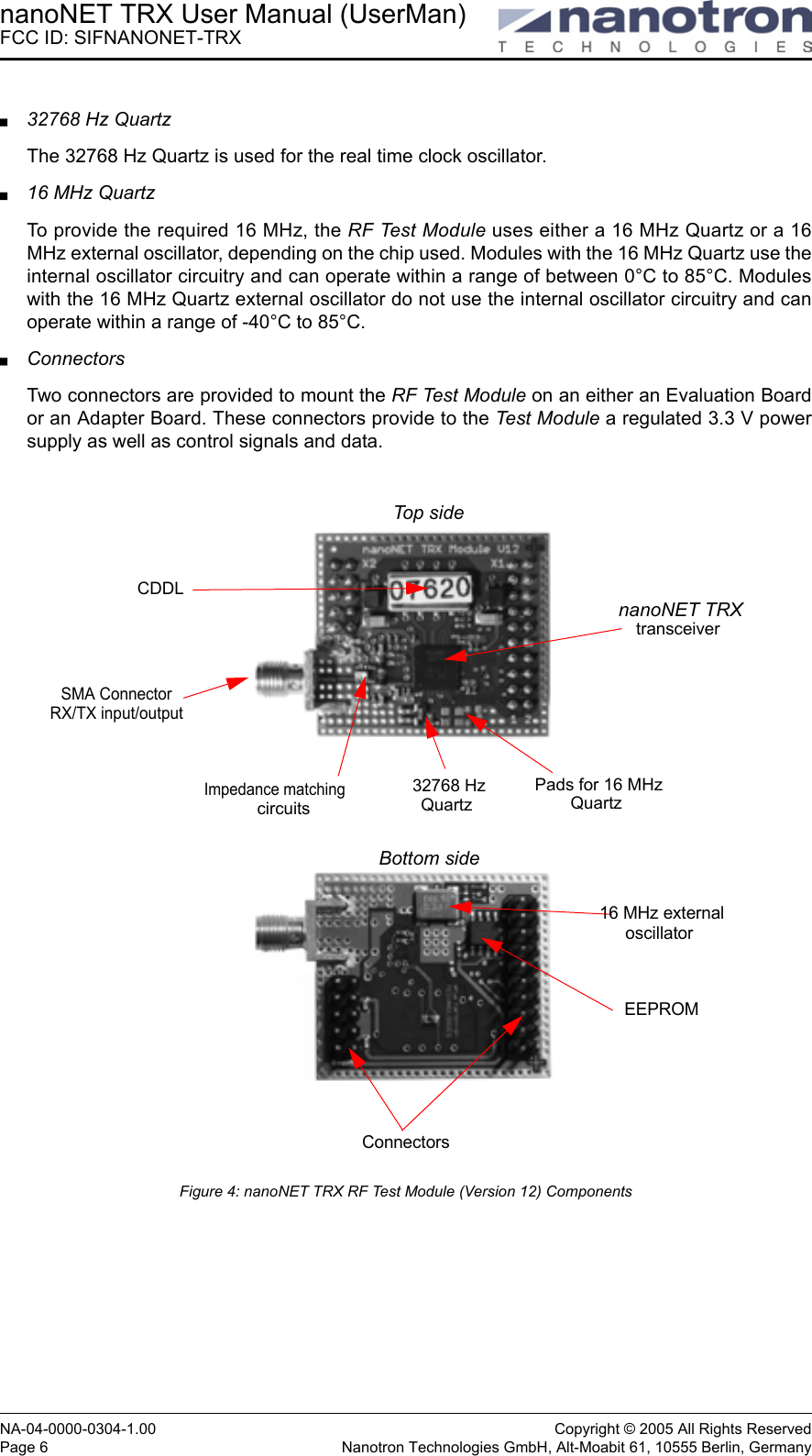
![nanoNET TRX User Manual (UserMan)FCC ID: SIFNANONET-TRXCopyright © 2005 All Rights Reserved NA-04-0000-0304-1.00Nanotron Technologies GmbH, Alt-Moabit 61, 10555 Berlin, Germany Page 237.2. Azimuth Diagram for Model 17010.11The following shows the Azimuth diagram for the antenna model 17010.11 measured at 2.40 GHz, 2.45 GHz, and 2.50 GHzFigure 24: Azimuth Diagram for Antenna model 17010.11Beam Peak ValuesNull depth valuesFrequency [dB] at [deg]2.40 GHz 0.85 61.972,45 GHz -0.38 111.942,50 GHz -0.69 143.92Frequency [dB] at [deg]2.40 GHz -2.26 135.922,45 GHz -3.57 125.932,50 GHz -2.59 113.94](https://usermanual.wiki/Nanotron-Technologies/NANONET-TRX/User-Guide-510418-Page-29.png)
