Neuralynx SAT-TX SMALL ANIMAL TELEMETRY TX User Manual sat radio tx
Neuralynx, Inc. SMALL ANIMAL TELEMETRY TX sat radio tx
UserManual.wiki
>
Neuralynx
>
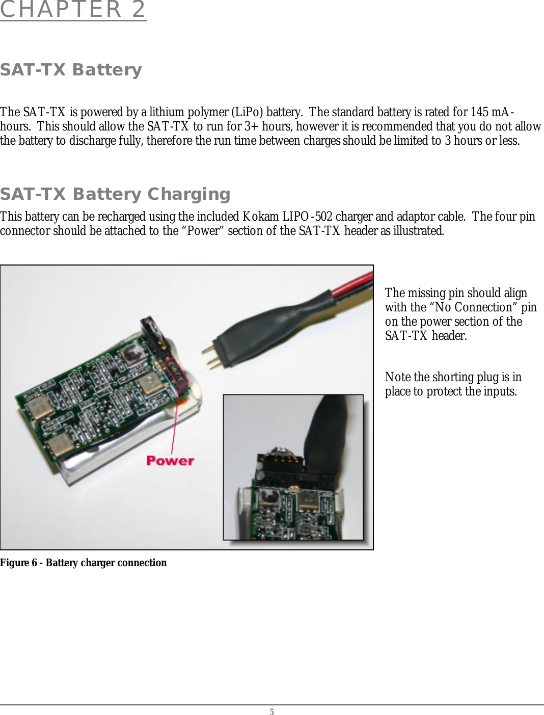
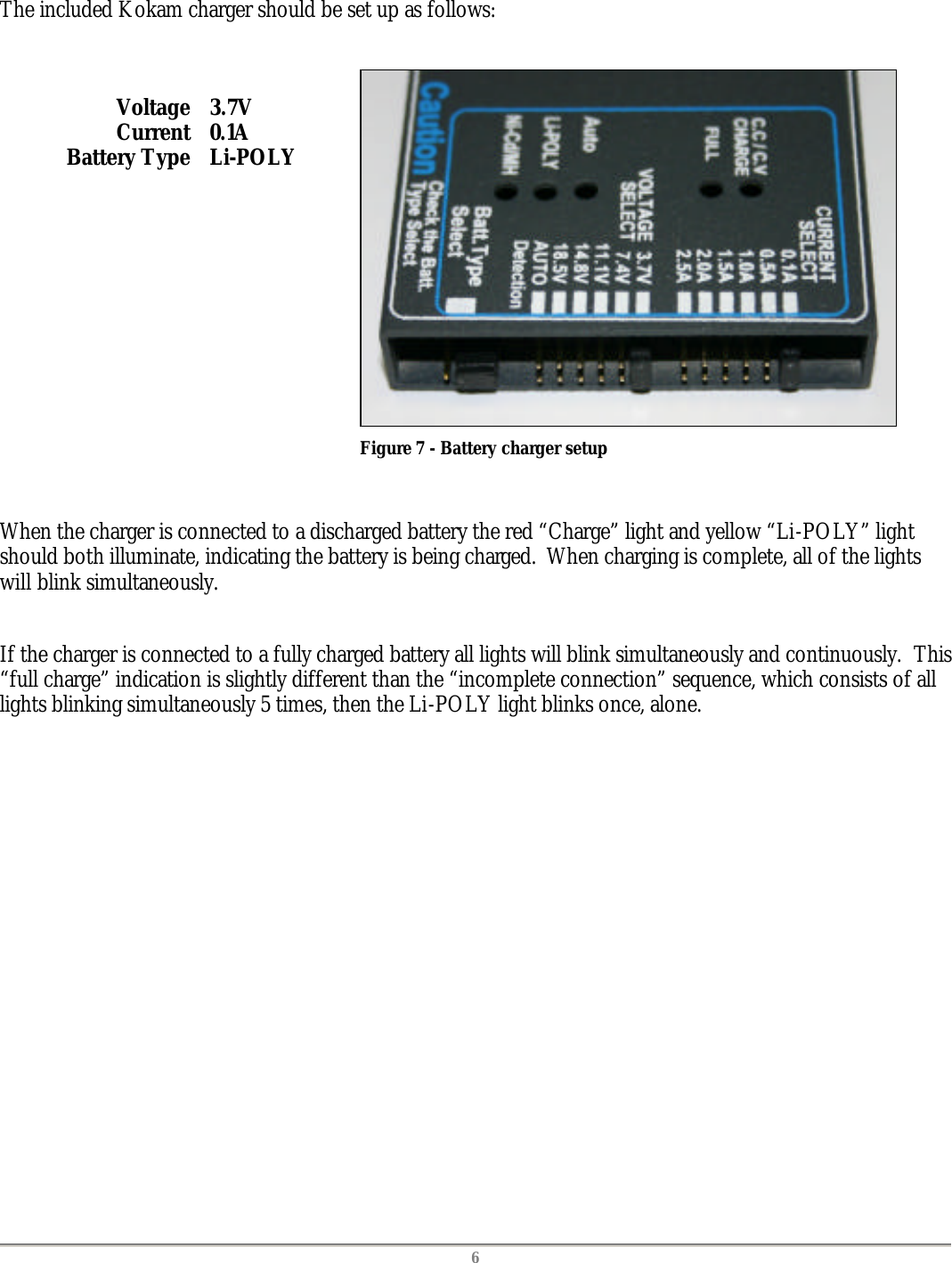
SAT TX User Manual
users manual
Navigation menu
Upload a User Manual
Namespaces
Wiki Guide
HTML
PDF
Info
Views
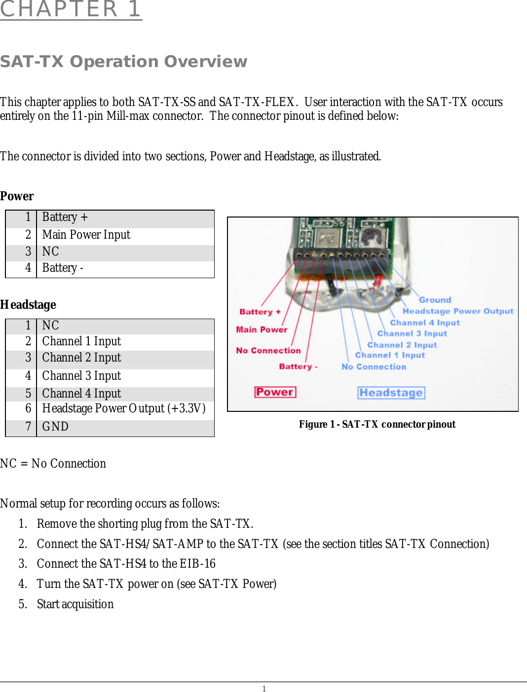
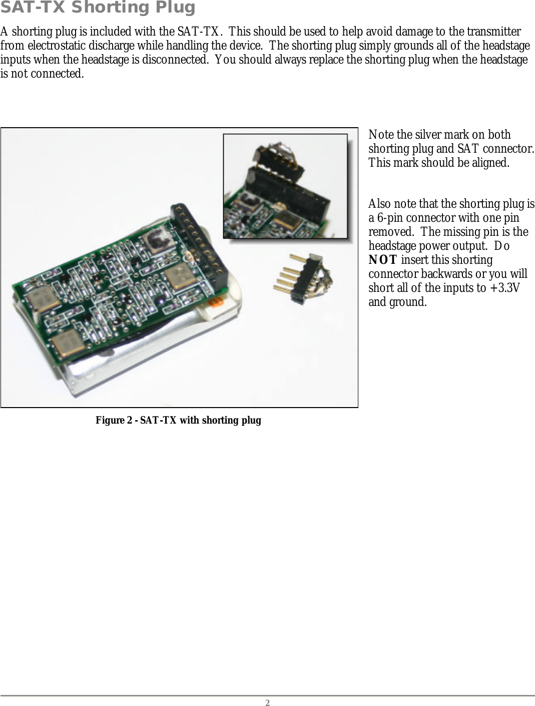
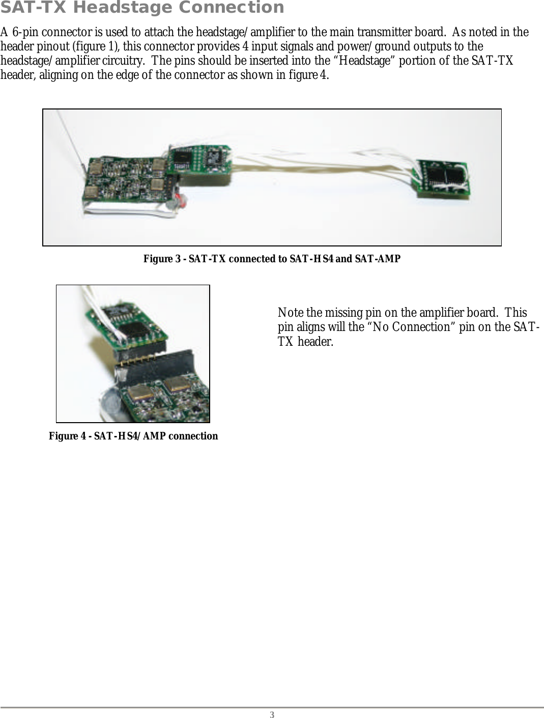
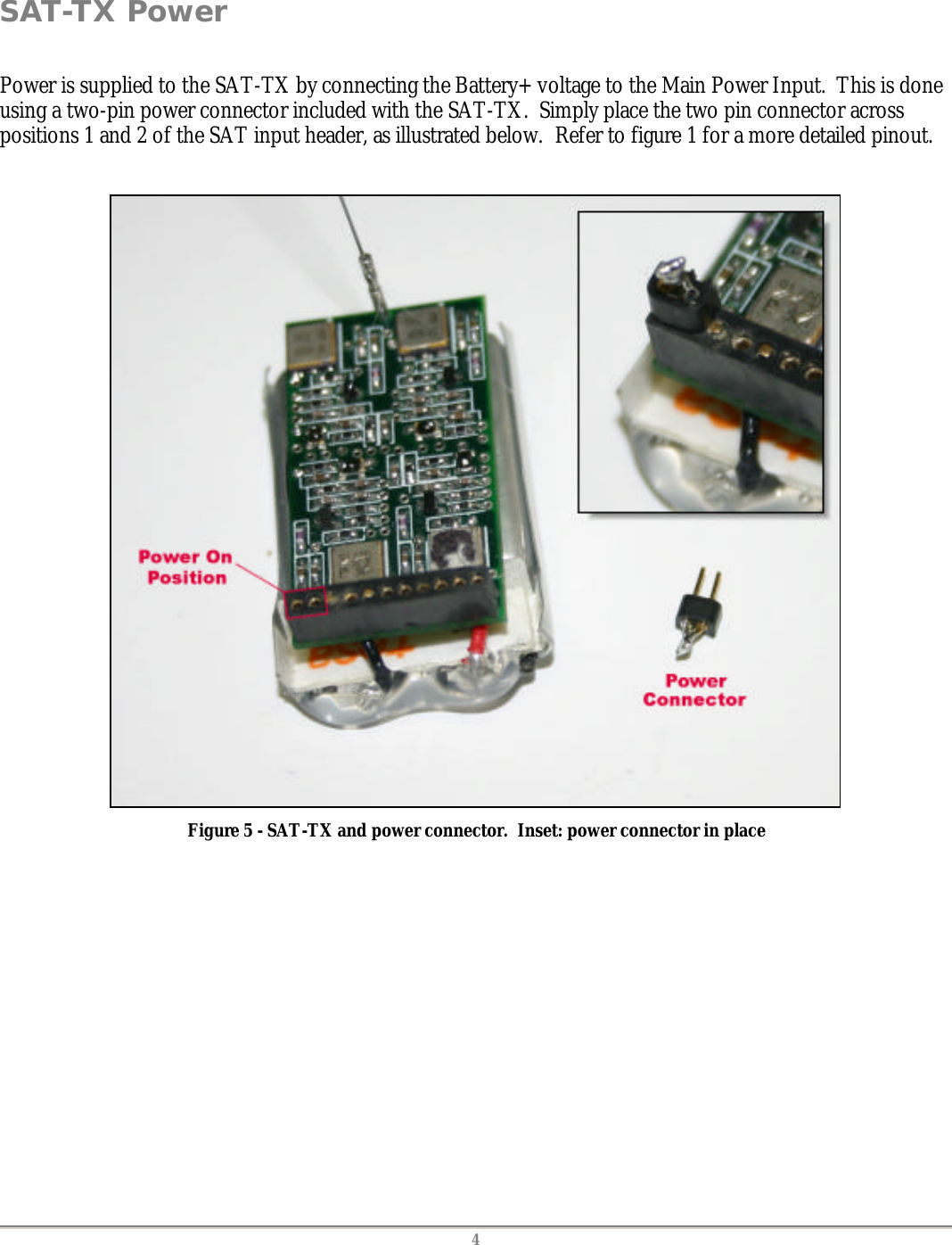
User Manual
Discussion / Help
Navigation