Noke DESS1 Electric door strike lock controller User Manual

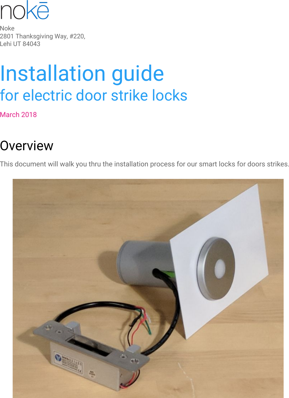
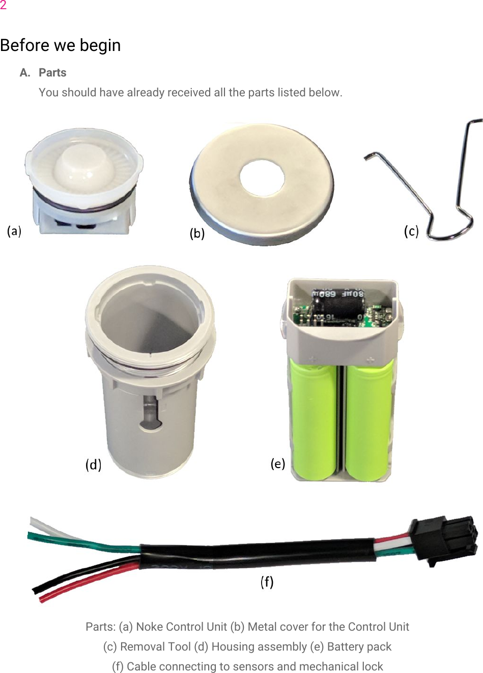
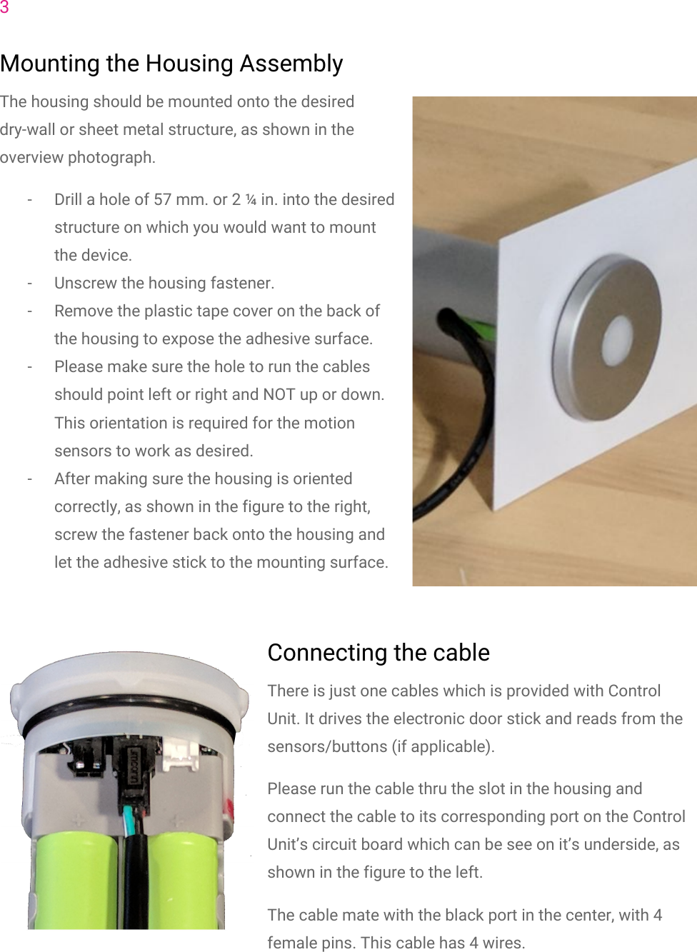
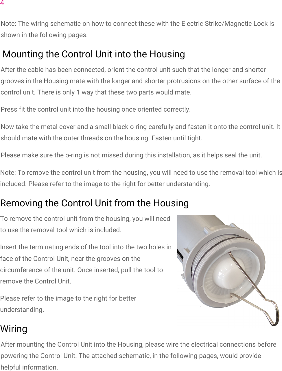
Noke Electric door strike lock controller

User Manual

Noke2801 Thanksgiving Way, #220, Lehi UT 84043 Installation guidefor electric door strike locksMarch 2018OverviewThis document will walk you thru the installation process for our smart locks for doors strikes.
2Before we beginA. PartsYou should have already received all the parts listed below.Parts: (a) Noke Control Unit (b) Metal cover for the Control Unit(c) Removal Tool (d) Housing assembly (e) Battery pack(f) Cable connecting to sensors and mechanical lock
3Mounting the Housing AssemblyThe housing should be mounted onto the desireddry-wall or sheet metal structure, as shown in theoverview photograph.- Drill a hole of 57 mm. or 2 ¼ in. into the desiredstructure on which you would want to mountthe device.- Unscrew the housing fastener.- Remove the plastic tape cover on the back ofthe housing to expose the adhesive surface.- Please make sure the hole to run the cablesshould point left or right and NOT up or down.This orientation is required for the motionsensors to work as desired.- After making sure the housing is orientedcorrectly, as shown in the figure to the right,screw the fastener back onto the housing andlet the adhesive stick to the mounting surface.Connecting the cableThere is just one cables which is provided with ControlUnit. It drives the electronic door stick and reads from thesensors/buttons (if applicable).Please run the cable thru the slot in the housing andconnect the cable to its corresponding port on the ControlUnit’s circuit board which can be see on it’s underside, asshown in the figure to the left.The cable mate with the black port in the center, with 4female pins. This cable has 4 wires.
4Note: The wiring schematic on how to connect these with the Electric Strike/Magnetic Lock isshown in the following pages. Mounting the Control Unit into the HousingAfter the cable has been connected, orient the control unit such that the longer and shortergrooves in the Housing mate with the longer and shorter protrusions on the other surface of thecontrol unit. There is only 1 way that these two parts would mate.Press fit the control unit into the housing once oriented correctly.Now take the metal cover and a small black o-ring carefully and fasten it onto the control unit. Itshould mate with the outer threads on the housing. Fasten until tight.Please make sure the o-ring is not missed during this installation, as it helps seal the unit.Note: To remove the control unit from the housing, you will need to use the removal tool which isincluded. Please refer to the image to the right for better understanding.Removing the Control Unit from the HousingTo remove the control unit from the housing, you will needto use the removal tool which is included.Insert the terminating ends of the tool into the two holes inface of the Control Unit, near the grooves on thecircumference of the unit. Once inserted, pull the tool toremove the Control Unit.Please refer to the image to the right for betterunderstanding.WiringAfter mounting the Control Unit into the Housing, please wire the electrical connections beforepowering the Control Unit. The attached schematic, in the following pages, would providehelpful information.
5-Black wire is ground reference.-Red goes to the Red of the Door strike. Black from the Door strike connects with ground.- If the Exit button and/or Door position sensor are applicable:Green goes to one terminal of the Exit button and the other terminal is grounded.White goes to one wire of the door sensor and the other wire is grounded.
6Figure: Wiring schematic for Door Strikes powered by Battery pack
FCC Statement This equipment has been tested and found to comply with the limits for a Class B digital device, pursuant to part 15 of the FCC rules. These limits are designed to provide reasonable protection against harmful interference in a residential installation. This equipment generates, uses and can radiate radio frequency energy and, if not installed and used in accordance with the instructions, may cause harmful interference to radio communications. However, there is no guarantee that interference will not occur in a particular installation. If this equipment does cause harmful interference to radio or television reception, which can be determined by turning the equipment off and on, the user is encouraged to try to correct the interference by one or more of the following measures: -Reorient or relocate the receiving antenna. -Increase the separation between the equipment and receiver. -Connect the equipment into an outlet on a circuit different from that to which the receiver is connected. -Consult the dealer or an experienced radio/TV technician for help. To assure continued compliance, any changes or modifications not expressly approved by the party. Responsible for compliance could void the user’s authority to operate this equipment. (Example- use only shielded interface cables when connecting to computer or peripheral devices). This equipment complies with Part 15 of the FCC Rules. Operation is subject to the following two conditions:     (1) This device may not cause harmful interference, and (2) This device must accept any interference received, including interference that may cause undesired operation.     RF warning statement: The device has been evaluated to meet general RF exposure requirement. The device can be used in portable exposure condition without restriction.

Navigation menu