Nordic ID NUR10W Nordic ID UHF RFID Reader NUR-10W User Manual
Nordic ID Oy Nordic ID UHF RFID Reader NUR-10W Users Manual
UserManual.wiki
>
Nordic ID
>
NUR10W User Manual
>
Users Manual
Contents
1.
Users Manual
2.
User
3.
Users manual
4.
Nordic ID Merlin_Quickguide_Multiling_V1006
5.
Safety and regulations_V1014_web
6.
Nordic ID EXA51 RF safety training_FCC_public
7.
Nordic ID EXA51_Datasheet_EU_V10
8.
Nordic ID EXA51_Quickguide_web_v08
Users Manual
Navigation menu
Upload a User Manual
Namespaces
Wiki Guide
HTML
PDF
Info
Views
User Manual
Discussion / Help
Navigation

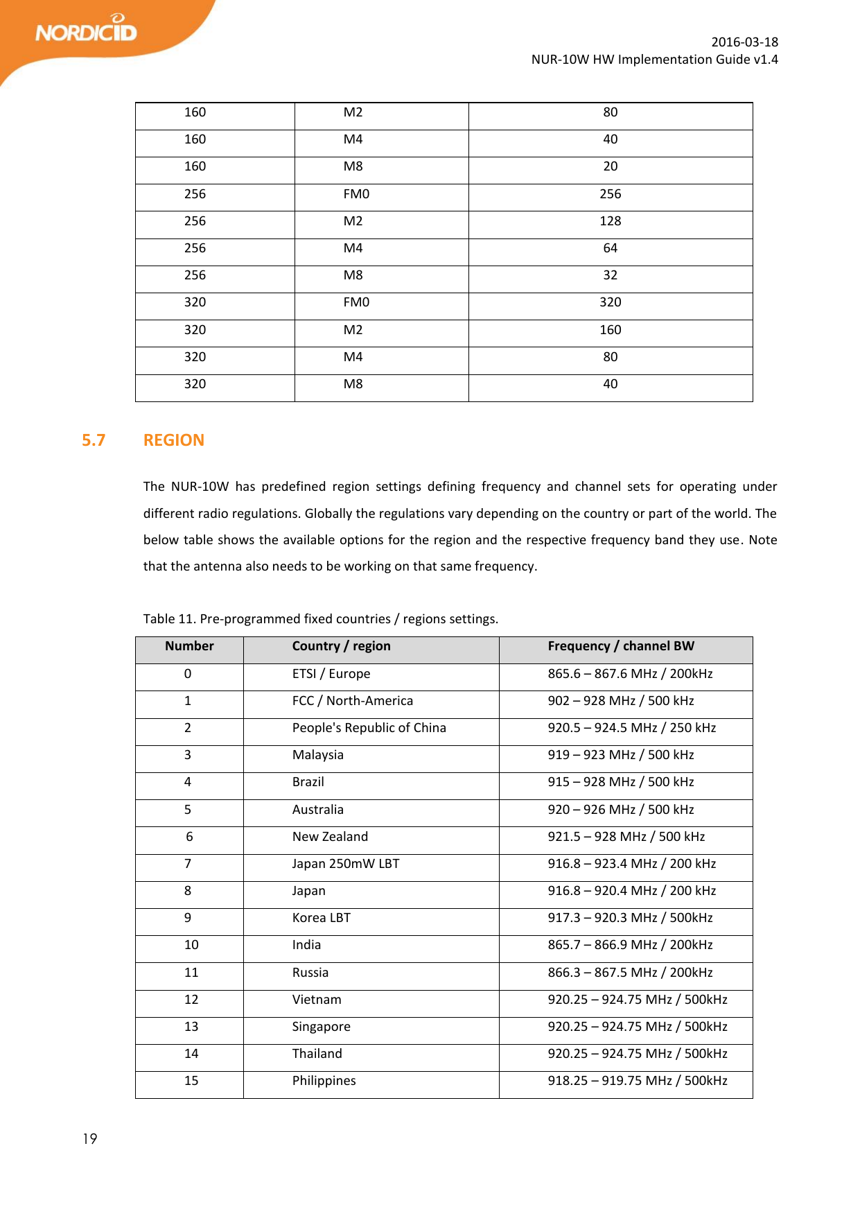

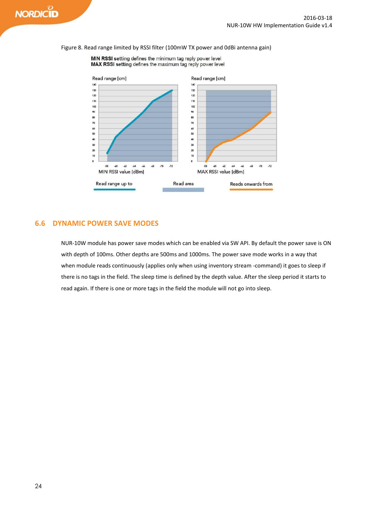

![39 2016-03-18 NUR-10W HW Implementation Guide v1.4 Česky [Czech] [name of manufacture] tímto prohlašuje, že tento [type of apparatus] je ve shodě sezákladními požadavky a dalšími příslušnými ustanoveními směrnice1999/5/ES. Dansk [Danish] Undertegnede [name of manufacture] erklærer herved, at følgende udstyr [type of apparatus] overholder de væsentlige krav og øvrige relevante krav i direktiv 1999/5/EF. Deutsch [German] Hiermit erklärt [name of manufacture], dass sich das Gerät [type of apparatus] in Übereinstimmung mit den grundlegenden Anforderungen und den übrigen einschlägigen Bestimmungen der Richtlinie 1999/5/EG befindet. Eesti [Estonian] Käesolevaga kinnitab [name of manufacture] seadme [type of apparatus] vastavust direktiivi 1999/5/EÜ põhinõuetele ja nimetatud direktiivist tulenevatele teistele asjakohastele sätetele. English Hereby, [name of manufacture], declares that this [type of apparatus] is in compliance with the essential requirements and other relevant provisions of Directive 1999/5/EC. Español [Spanish] Por medio de la presente [name of manufacture] declara que el [type of apparatus] cumple con los requisitos esenciales y cualesquiera otras disposiciones aplicables o exigibles de la Directiva 1999/5/CE. Ελληνική [Greek] ΜΕ ΤΗΝ ΠΑΡΟΥΣΑ [name of manufacture] ΔΗΛΩΝΕΙ ΟΤΙ [type of apparatus] ΣΥΜΜΟΡΦΩΝΕΤΑΙ ΠΡΟΣ ΤΙΣ ΟΥΣΙΩΔΕΙΣ ΑΠΑΙΤΗΣΕΙΣ ΚΑΙ ΤΙΣ ΛΟΙΠΕΣ ΣΧΕΤΙΚΕΣ ΔΙΑΤΑΞΕΙΣ ΤΗΣ ΟΔΗΓΙΑΣ 1999/5/ΕΚ. Français [French] Par la présente [name of manufacture] déclare que l'appareil [type of apparatus] est conforme aux exigences essentielles et aux autres dispositions pertinentes de la directive 1999/5/CE.](https://usermanual.wiki/Nordic-ID/NUR10W.Users-Manual/User-Guide-2940166-Page-39.png)
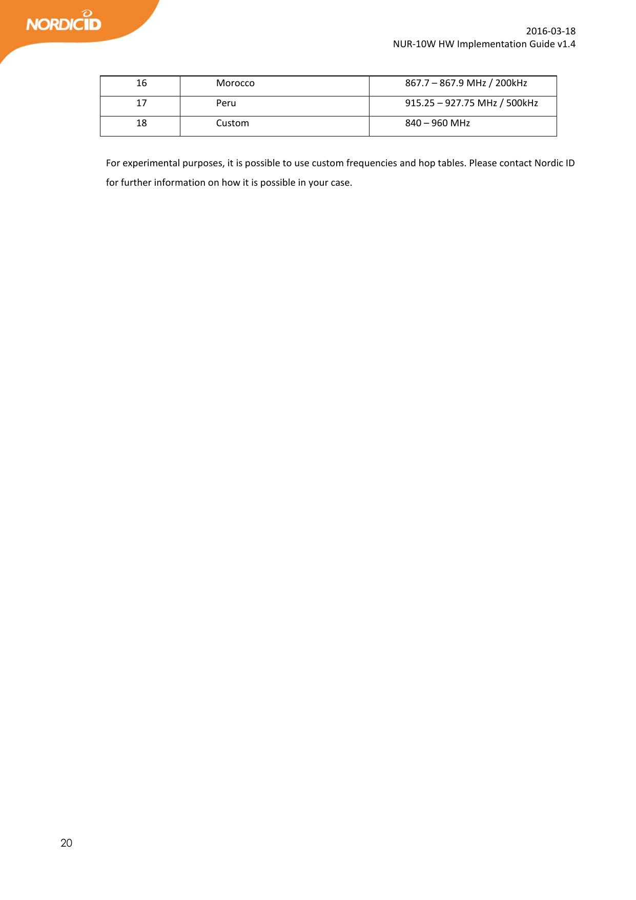
![40 2016-03-18 NUR-10W HW Implementation Guide v1.4 Italiano [Italian] Con la presente [name of manufacture] dichiara che questo [type of apparatus] è conforme ai requisiti essenziali ed alle altre disposizioni pertinenti stabilite dalla direttiva 1999/5/CE. Latviski [Latvian] Ar šo [name of manufacture] deklarē, ka [type of apparatus] atbilst Direktīvas 1999/5/EK būtiskajām prasībām un citiem ar to saistītajiem noteikumiem. Lietuvių [Lithuanian] Šiuo [name of manufacture] deklaruoja, kad šis [type of apparatus] atitinka esminius reikalavimus ir kitas 1999/5/EB Direktyvos nuostatas. Nederlands [Dutch] Hierbij verklaart [name of manufacture] dat het toestel [type of apparatus] in overeenstemming is met de essentiële eisen en de andere relevante bepalingen van richtlijn 1999/5/EG. Malti [Maltese] Hawnhekk, [name of manufacture], jiddikjara li dan [type of apparatus] jikkonforma mal-ħtiġijiet essenzjali u ma provvedimenti oħrajn relevanti li hemm fid-Dirrettiva 1999/5/EC. Magyar [Hungarian] Alulírott, [name of manufacture] nyilatkozom, hogy a [type of apparatus] megfelel a vonatkozó alapvetõ követelményeknek és az 1999/5/EC irányelv egyéb elõírásainak. Polski [Polish] Niniejszym [name of manufacture] oświadcza, że [type of apparatus] jest zgodny z zasadniczymi wymogami oraz pozostałymi stosownymi postanowieniami Dyrektywy 1999/5/EC. Português [Portuguese]](https://usermanual.wiki/Nordic-ID/NUR10W.Users-Manual/User-Guide-2940166-Page-40.png)
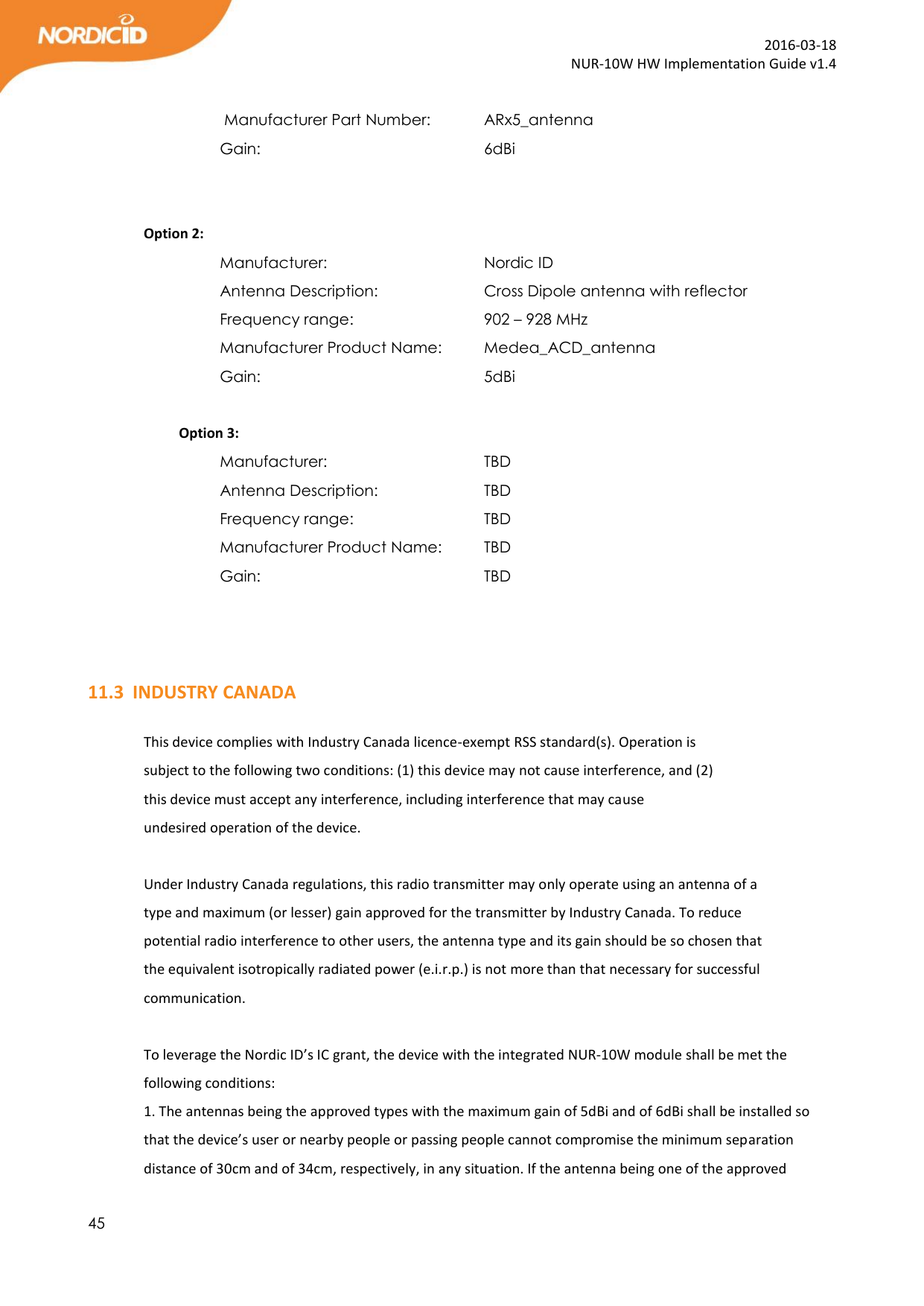
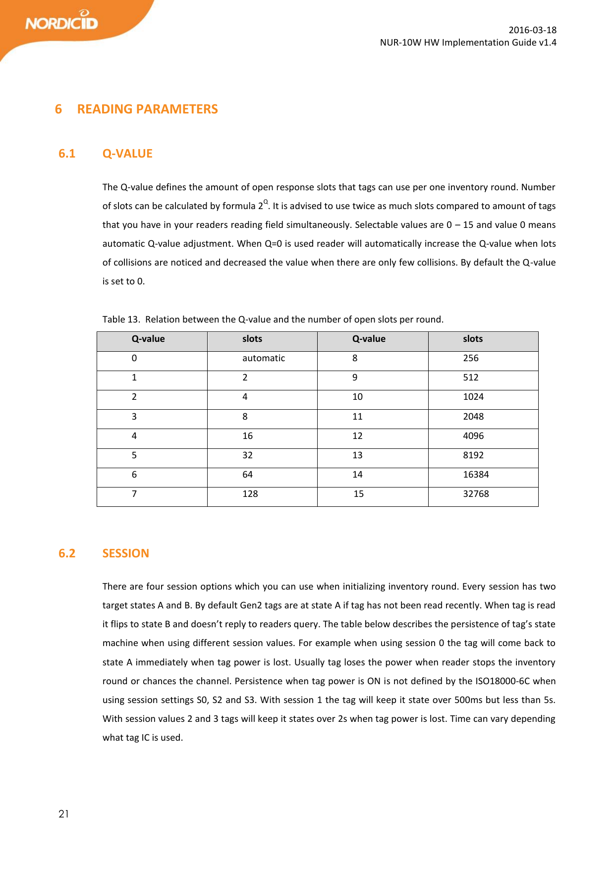
![41 2016-03-18 NUR-10W HW Implementation Guide v1.4 [name of manufacture] declara que este [type of apparatus] está conforme com os requisitos essenciais e outras disposições da Directiva 1999/5/CE. Slovensko [Slovenian] [name of manufacture] izjavlja, da je ta [type of apparatus] v skladu z bistvenimi zahtevami in ostalimi relevantnimi določili direktive 1999/5/ES. Slovensky [Slovak] [name of manufacture] týmto vyhlasuje, že [type of apparatus] spĺňa základné požiadavky a všetky príslušné ustanovenia Smernice 1999/5/ES. Suomi [Finnish] [name of manufacture] vakuuttaa täten että [type of apparatus] tyyppinen laite on direktiivin 1999/5/EY oleellisten vaatimusten ja sitä koskevien direktiivin muiden ehtojen mukainen. Svenska [Swedish] Härmed intygar [name of manufacture] att denna [type of apparatus] står i överensstämmelse med de väsentliga egenskapskrav och övriga relevanta bestämmelser som framgår av direktiv 1999/5/EG. LABELING REQUIREMENTS The 'CE' marking must be in a visible area on the OEM product. APPROVED ANTENNAS Maximum allowed ERP power is 33dBm. NUR-10W has output power of 30dBm. Meaning that 5dBi is the maximum allowed antenna gain without cable losses. Formula how to calculate maximum allowed antenna gain: 30 dBm – 2.15 (dipole gain) + [antenna gain dBi] – [cable attenuation dB] < 33dBm Beamwidth restrictions: For transmissions ≤500 mW e.r.p. there shall be no restriction on beamwidth. For transmissions of > 500 mW e.r.p. to ≤ 1 000 mW e.r.p. beamwidths shall be ≤ 180º For transmissions of > 1 000 mW e.r.p. to 2 000 mW e.r.p. beamwidths shall be ≤ 90º](https://usermanual.wiki/Nordic-ID/NUR10W.Users-Manual/User-Guide-2940166-Page-41.png)