Nordic ID RF650 Wireless data collection terminal User Manual RF650 Manual Version 1 1 ENG
Nordic ID Oy Wireless data collection terminal RF650 Manual Version 1 1 ENG
UserManual.wiki
>
Nordic ID
>
RF650 User Manual
User manual
Navigation menu
Upload a User Manual
Namespaces
Wiki Guide
HTML
PDF
Info
Views
User Manual
Discussion / Help
Navigation
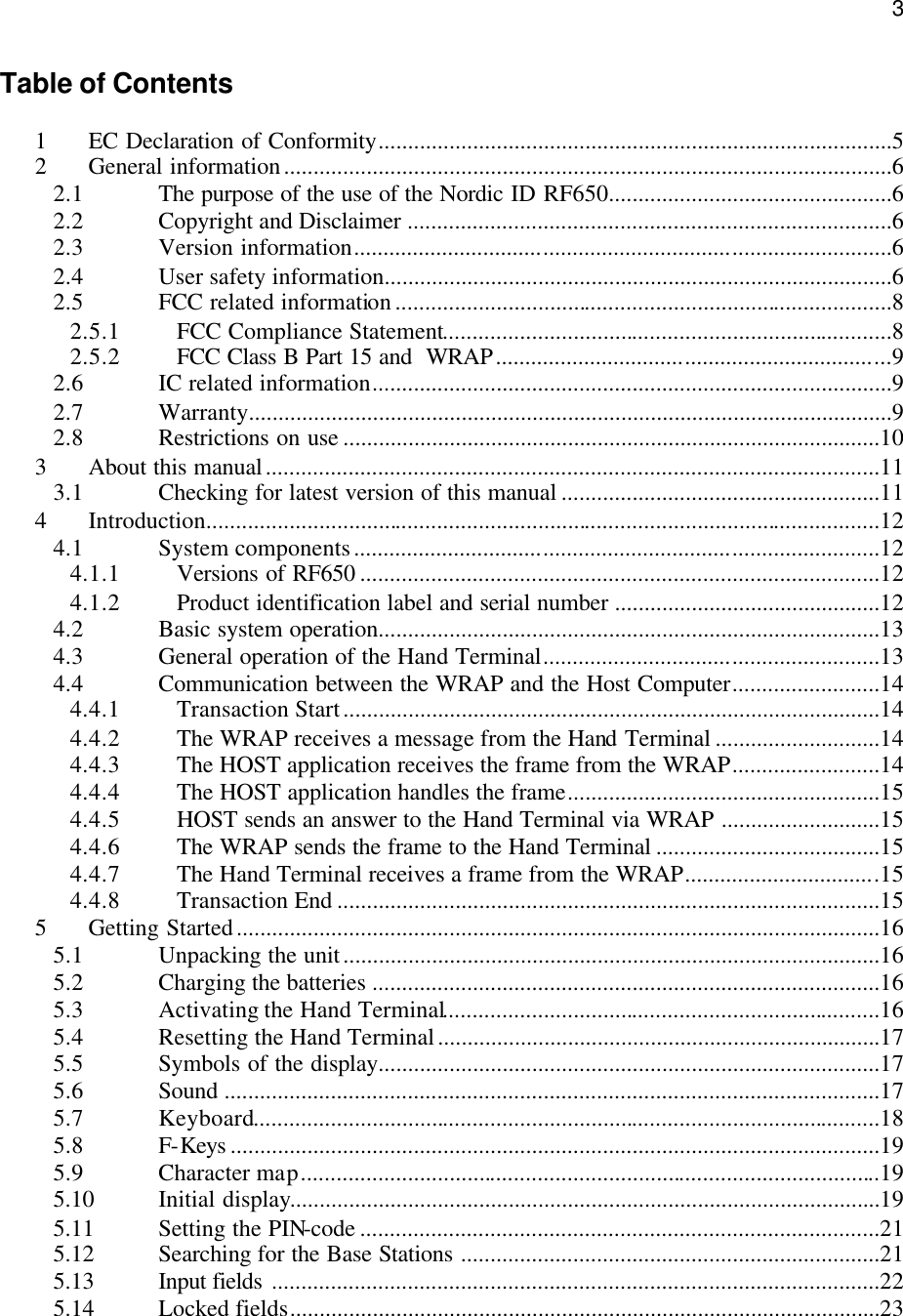
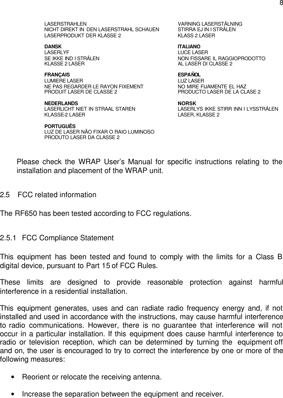
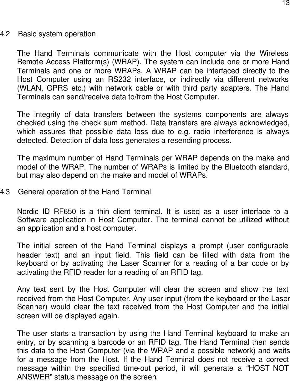
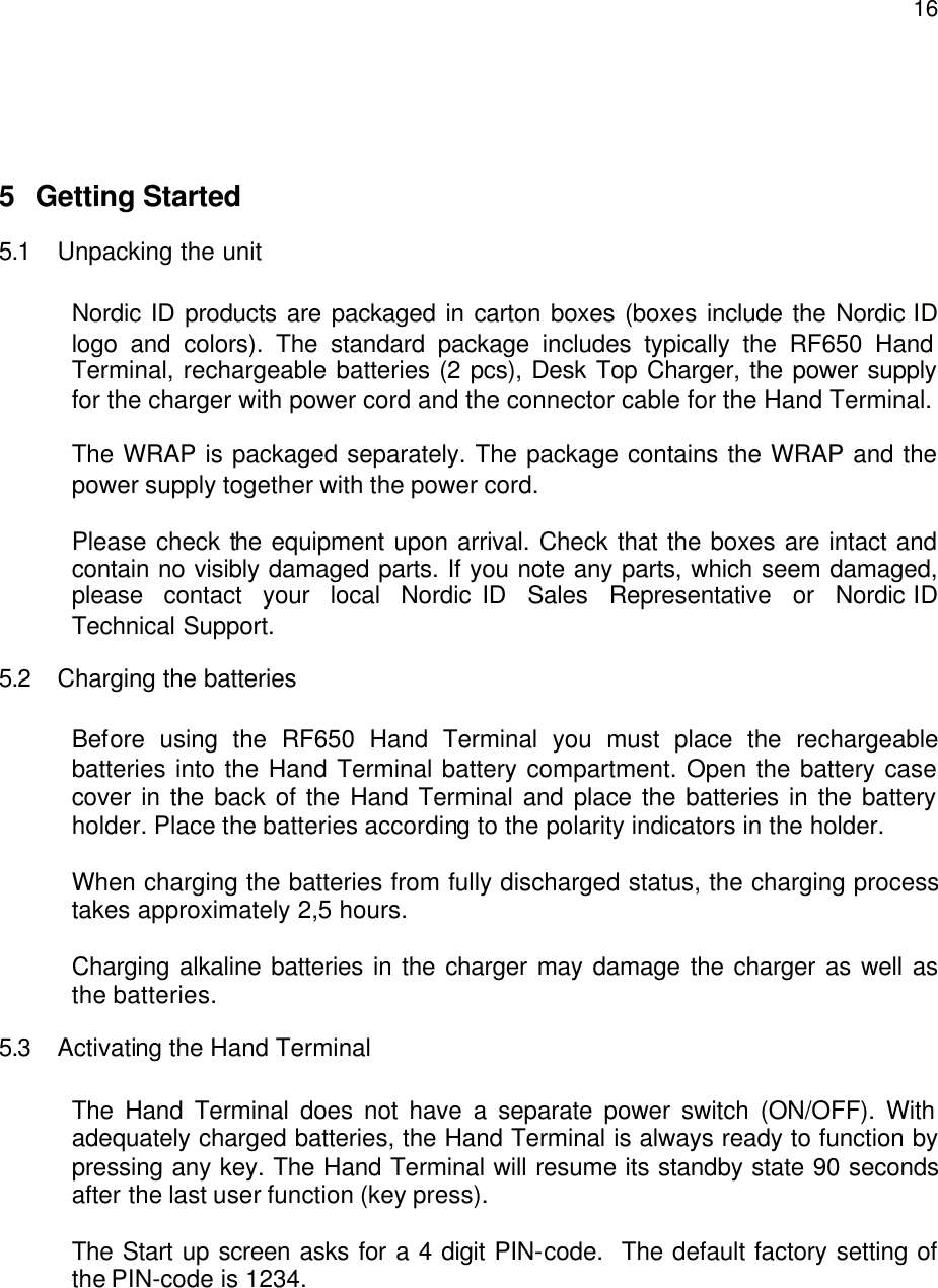
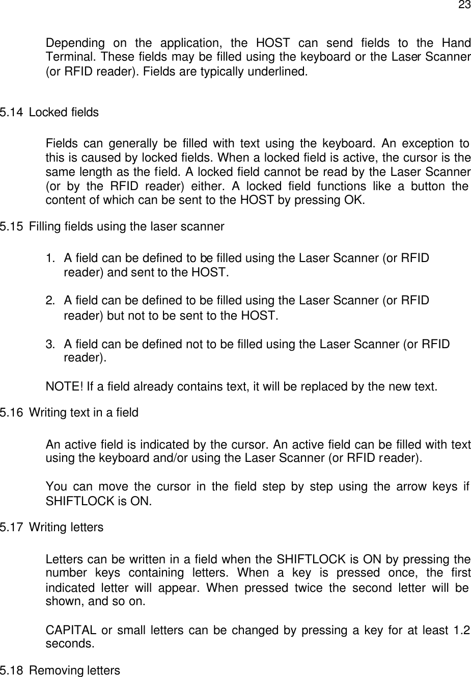
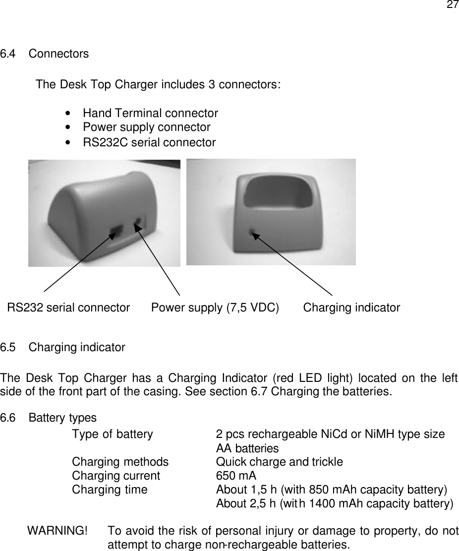
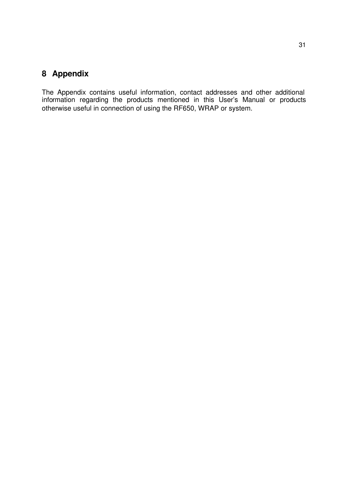
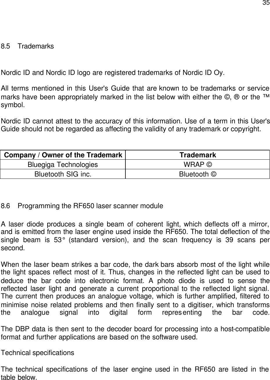
![185.7 Keyboard Key function table: Key Function with shift key (shift + key pressed at the same time ). Function with SHIFTLOCK Normal function Laser *** External reader will be activated if allowed by the current input field. In scanner mode: The Laser reader will be activated if allowed by the current input field. In light mode: The bright led will be on as long as key is down. F1 *** F6 F1 F2 *** F7 F2 F3 *** F8 F3 F4 *** F9 F4 F5 *** F10 F5 OK Keylock ON / OFF Normal function The cursor will be moved to the next field and/or the content of the field sent to the HOST if allowed by the current field definition Arrow up Scrolls display upward Moves the cursor step by step to the left. Displays the previous field of the form. Arrow down Scrolls display downward Moves the cursor step by step to the right. Displays the next field of the form. Shift *** SHIFTLOCK OFF SHIFTLOCK ON 7 *** ABC abc 7 8 *** DEF def 8 9 *** GHI ghi 9 4 *** JKL jkl 4 5 *** MNO mno 5 6 *** PQR pqr 6 1 Receiver mode on/off STU stu 1 2 *** VWX vwx 2 3 *** YZÅÄÖ yzåäö 3 . Scanner / Light ↵ : ; ! ? " # & @ | . 0 MENU < > [ ] Ü { } ( ) ü 0 - Backlight (option) Spc + * / % = $ £ ± ½ - DEL Reset Normal function Removes a character from the current field.](https://usermanual.wiki/Nordic-ID/RF650/User-Guide-459759-Page-18.png)
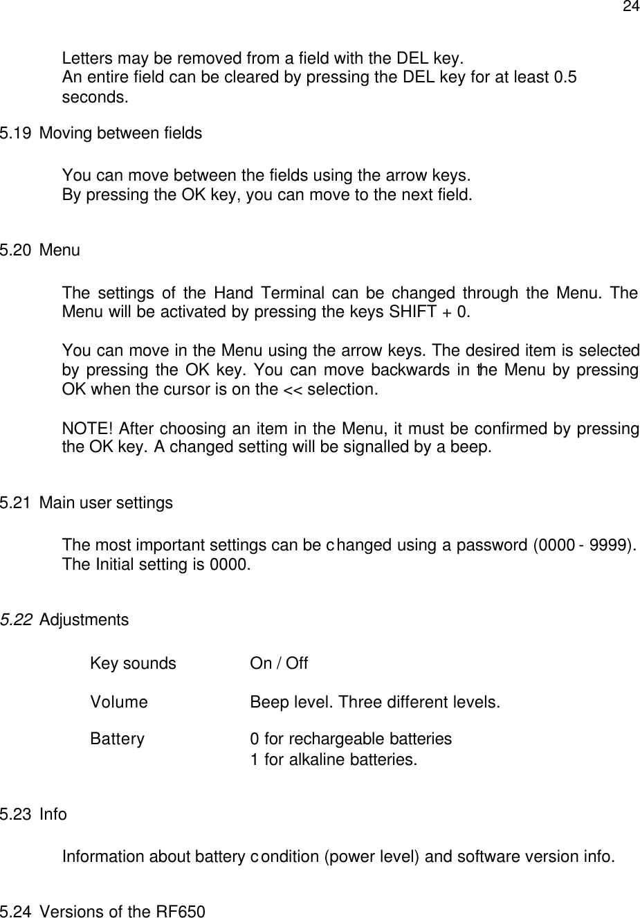
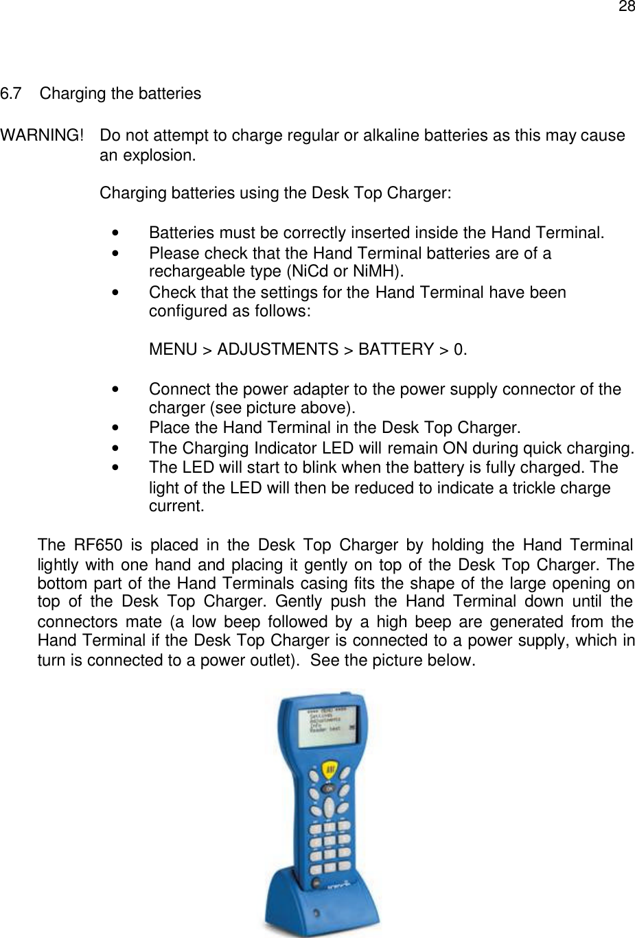
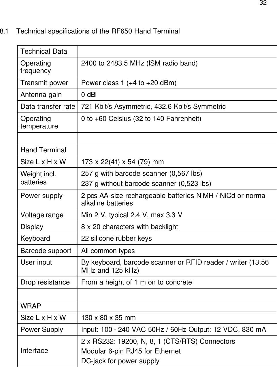
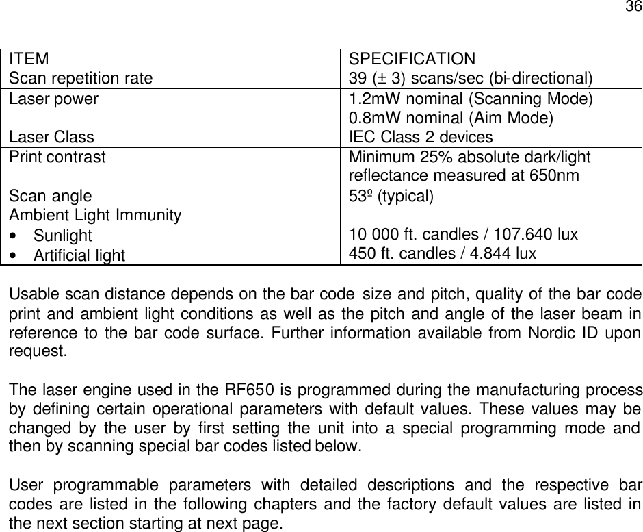
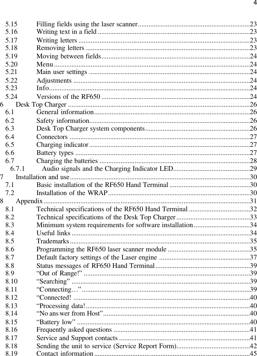
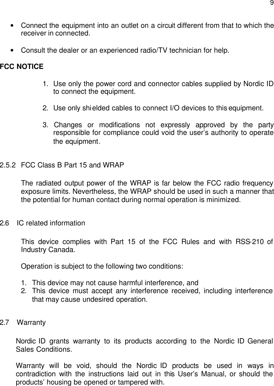
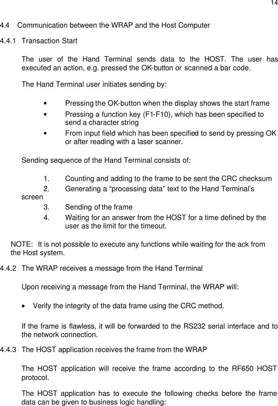
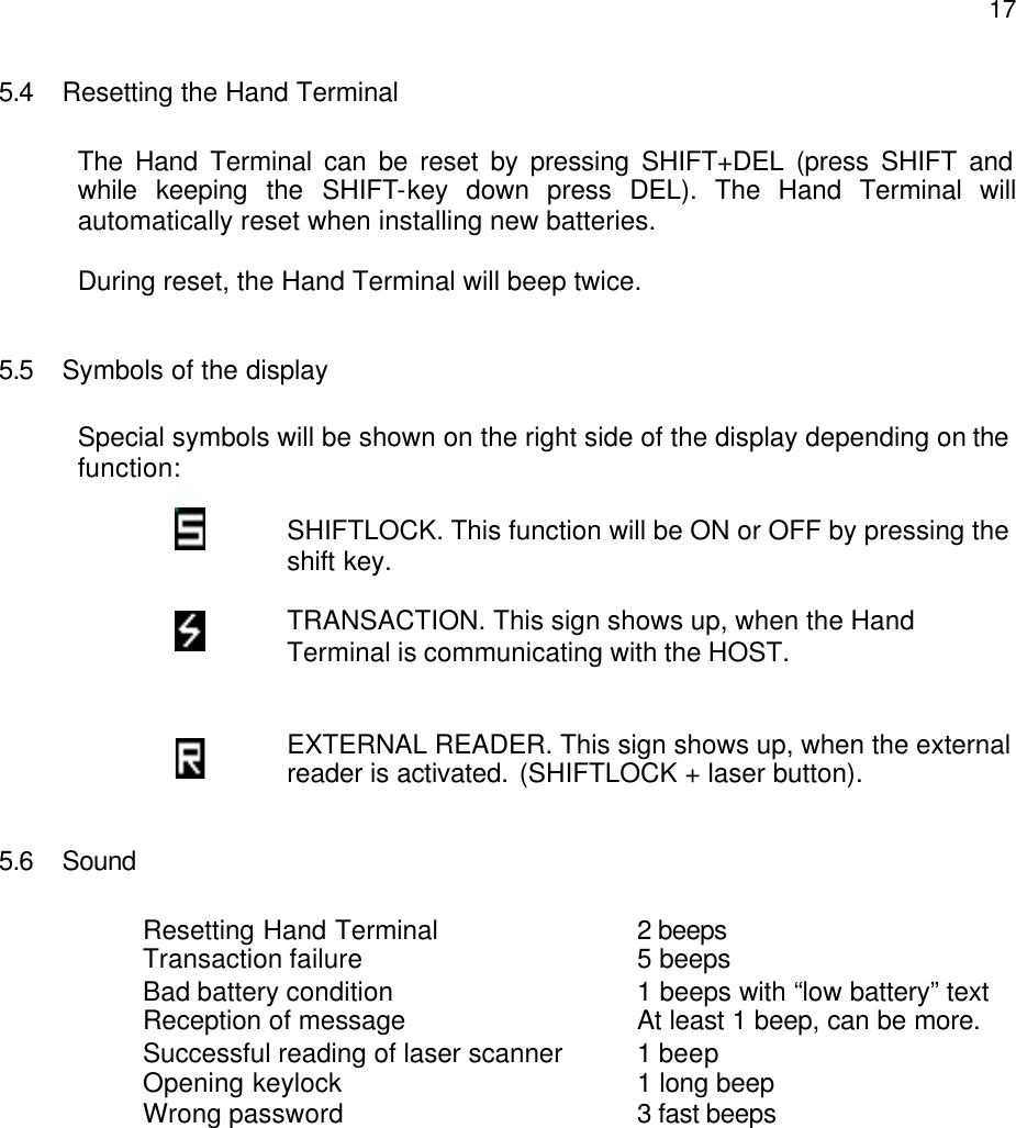
![21NOTE! Usually the Host Application has been defined to take control of the display contents immediately after the connection between the RF650 and the WRAP has been established. 5.11 Setting the PIN-code Before the RF650 Hand Terminal can be used in a host application environment, the PIN-code of the Bluetooth system needs to be set on the Hand Terminal. Standard practice is that the system administrator sets the PIN-code on the Hand Terminal units. How to set the PIN-code on the RF650 Hand Terminal The PIN-code is set using the ”Settings” menu on the unit. 1. Press SHIFT + 0 from the keyboard (Shift needs to be pressed down as you press 0) 2. Select “Settings” with the arrow keys and press OK 3. Type in the password (0000-9999), or if it has not been set up, just press OK 4. Select ”PIN code” and press OK 5. Type in a PIN-code between 0000-9999 and press OK After setting up the PIN-code, a screen that searches for the Base Stations will appear: 5.12 Searching for the Base Stations Select [SEARCH] and press OK. The RF650 Hand Terminal will begin to search for base stations automatically after power-up and this will usually take 15 – 30 seconds. A list will appear on the RF650 display listing all the names of the Bluetooth devices nearby.](https://usermanual.wiki/Nordic-ID/RF650/User-Guide-459759-Page-21.png)
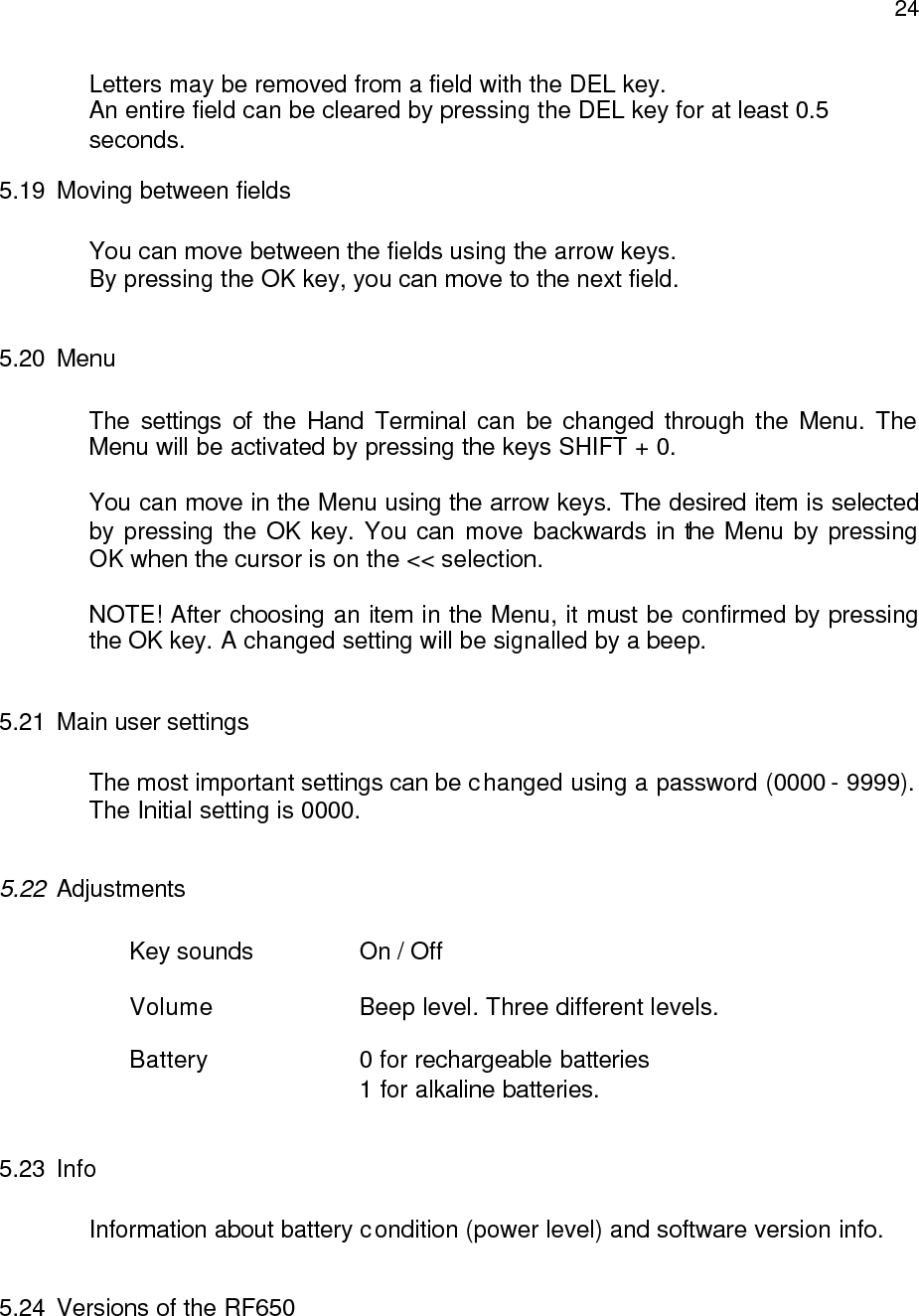
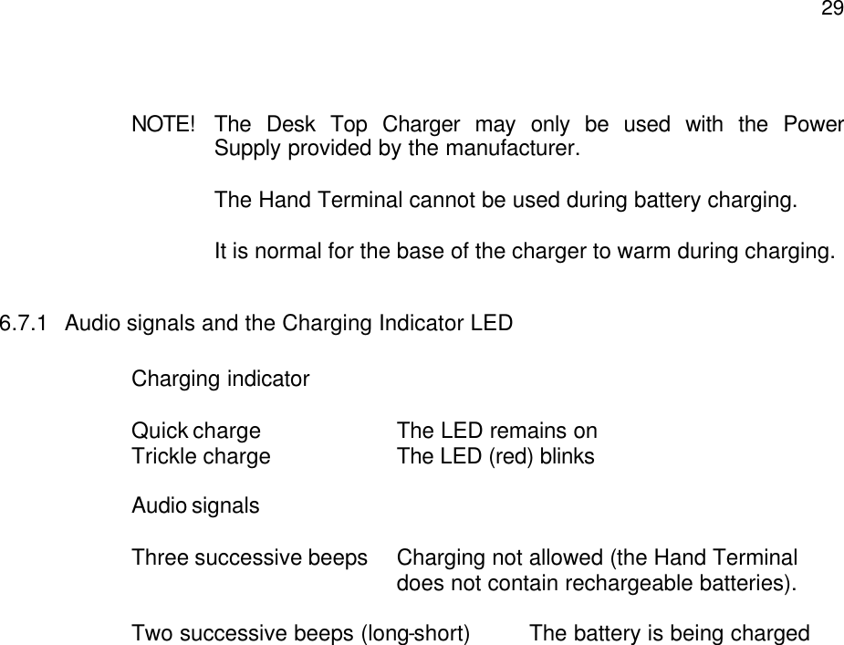
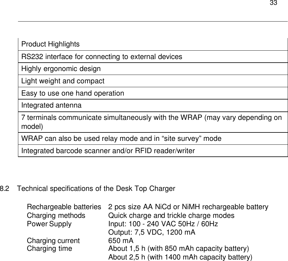
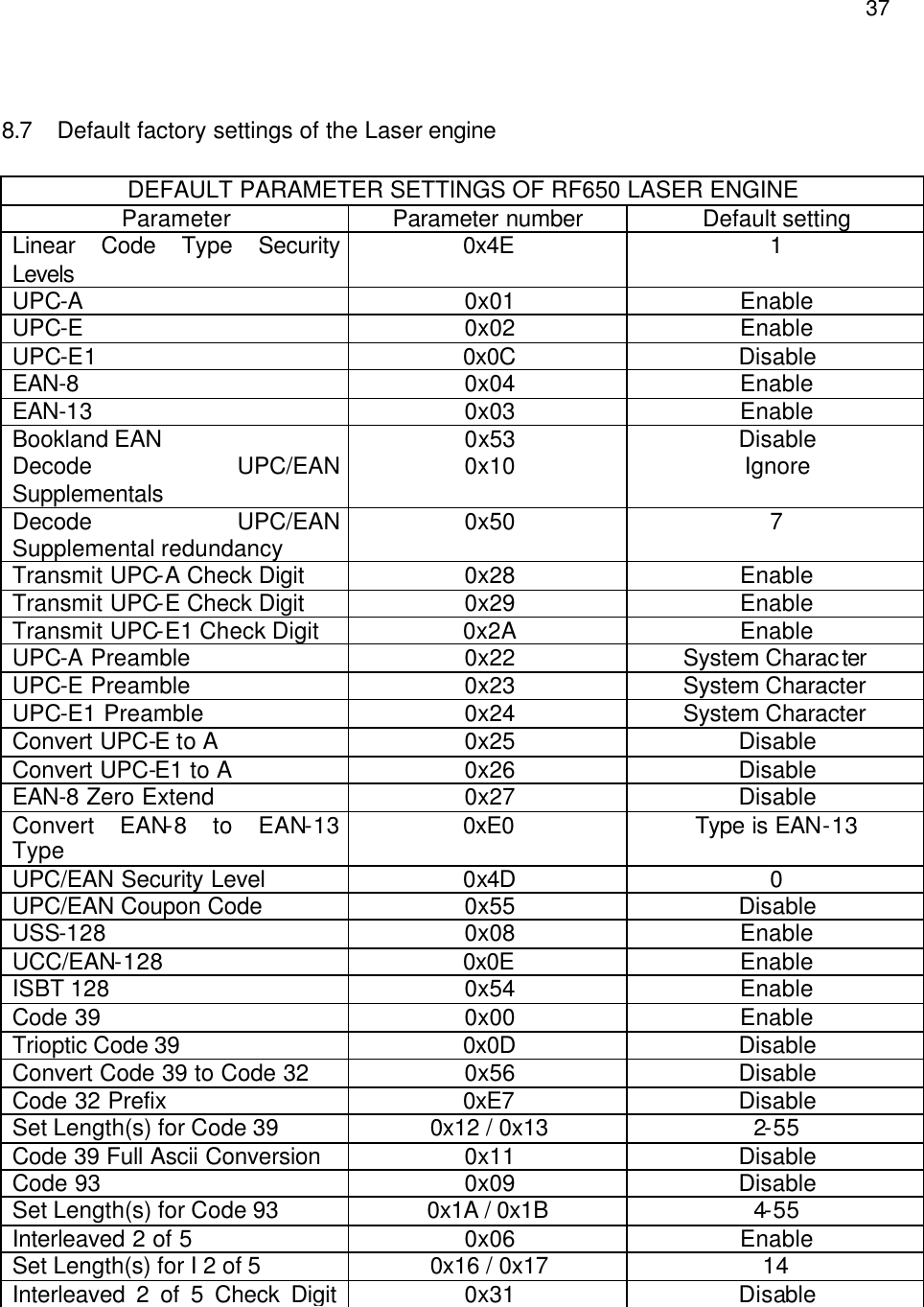
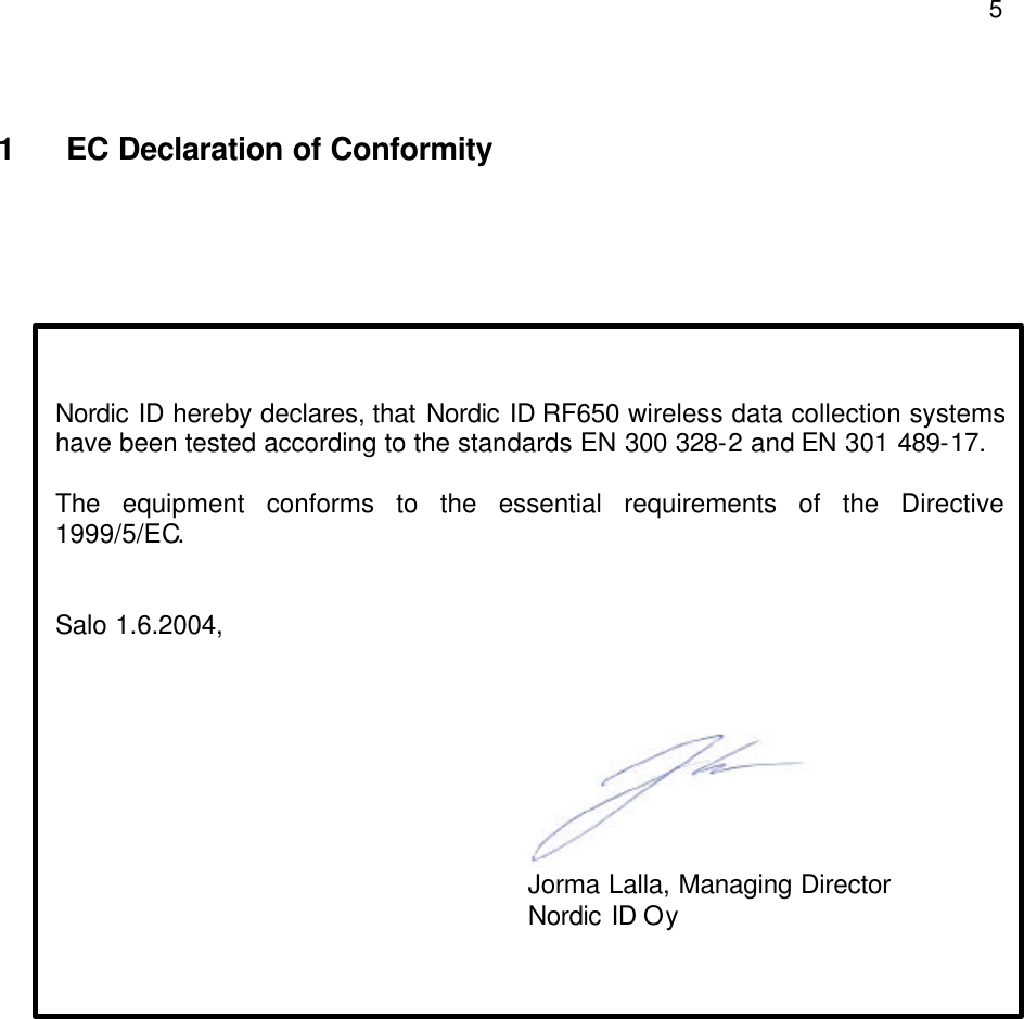
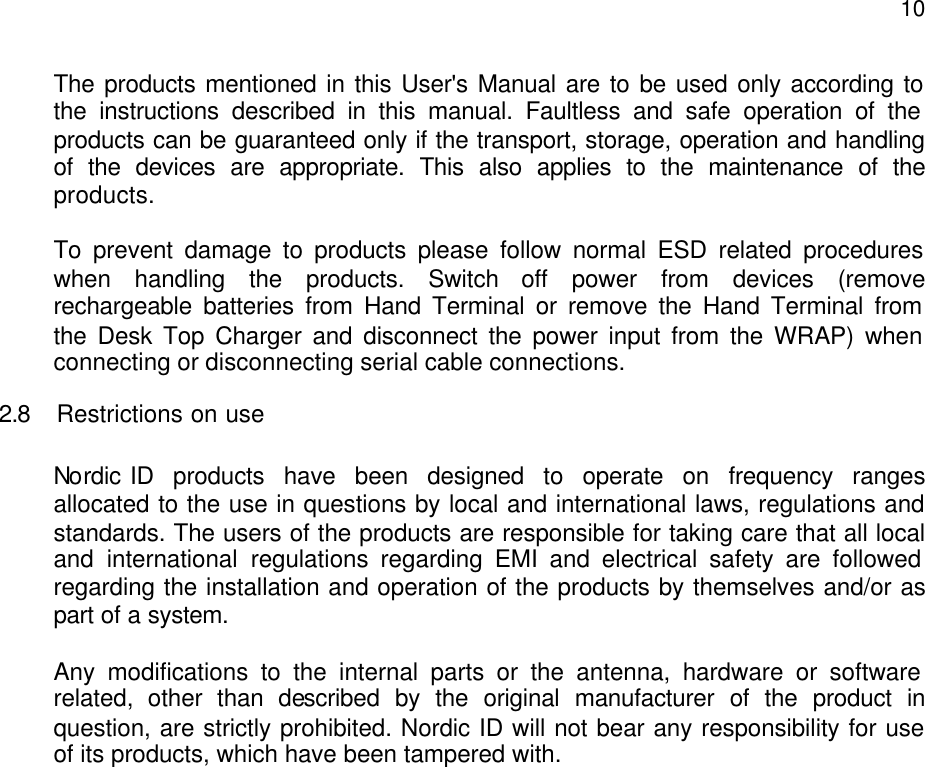
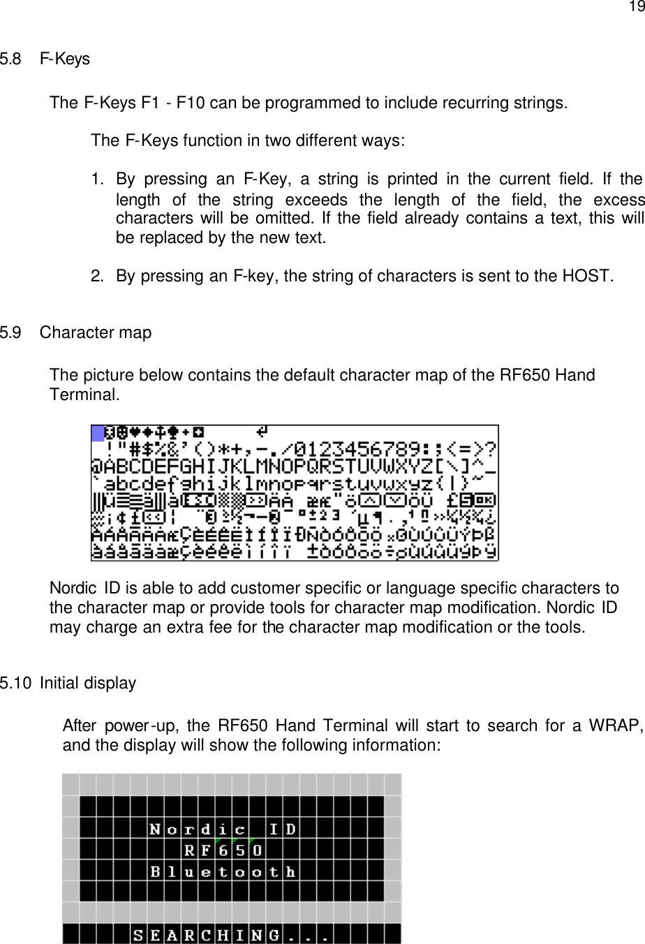
![22 Other Bluetooth devices apart from WRAP (such as mobile phones) may also appear on the list. The WRAP can be recognized by the name, which the system administrator has set for it. If there are no WRAPs listed when the text ”NO MORE BS” appears on the display, restart the search process by selecting [SEARCH]. Select a WRAP, which has the same PIN-code as the Hand Terminal, from the list and press OK. After selecting the WRAP the Hand Terminal will form a connection to the WRAP. After the Hand Terminal has succeeded in connecting with the WRAP the Hand Terminal will receive the Bluetooth addresses of all the Base Stations that are connected to the network (have the same PIN-code). The Bluetooth addresses will be saved in the memory of the Hand Terminal. When the connection to the network has been successfully performed, the Hand Terminal will beep three times quickly in succession, after which it will beep separate beeps one each for a found WRAPs (e.g. five WRAPs found, five beeps). The Hand Terminal is now ready to communicate with the host system. The host system may have a function, which allows only Hand Terminals with a certain CommID to use the system. The system administrator has to see to it that CommIDs of all new Hand Terminals to be used in the system are saved in the host system. CommID is a unique identification number for the Hand Terminal. By using the CommID, the Host System is able to separate the Hand Terminals from each other. CommID is printed on the ID label located under the rechargeable batteries of the Hand Terminal but may also be checked from the internal menu (INFO). 5.13 Input fields The RF650 Hand Terminal has a virtual display page of 12 x 20 characters. The actual display size is 8 x 20 characters, thus 2/3 of the virtual page can be viewed at a time.](https://usermanual.wiki/Nordic-ID/RF650/User-Guide-459759-Page-22.png)