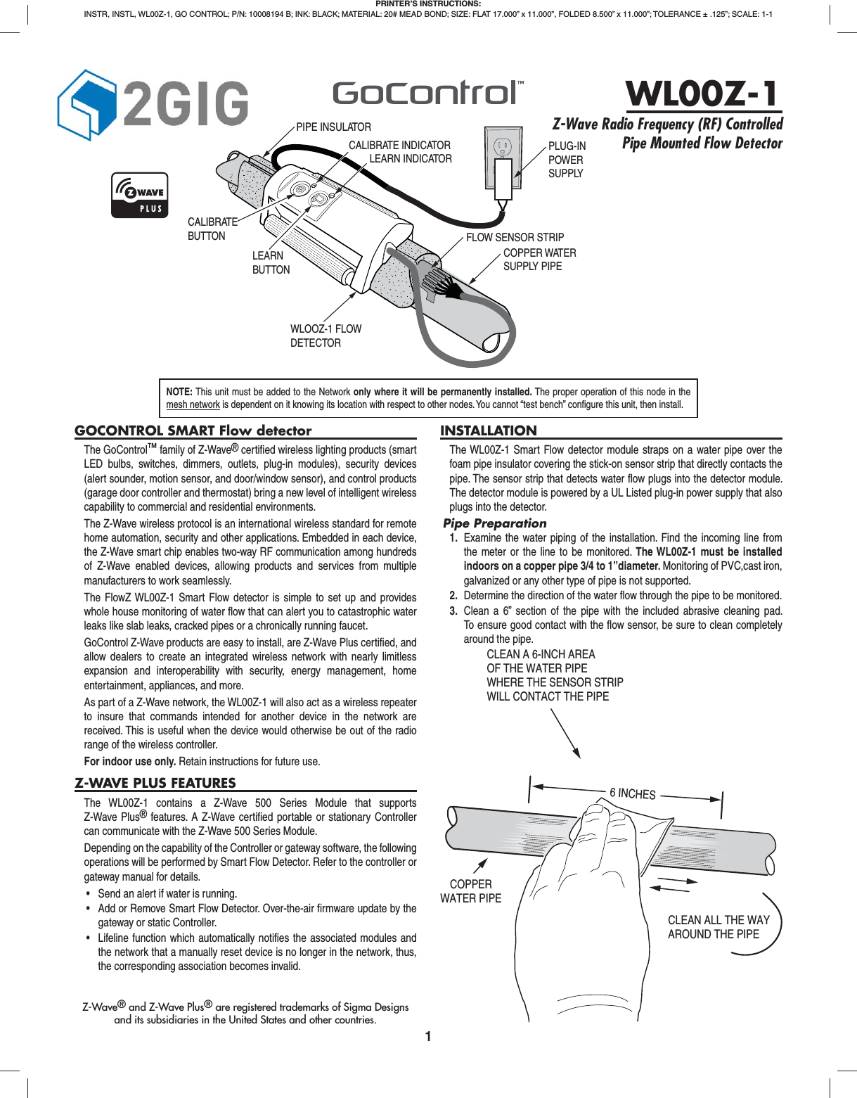
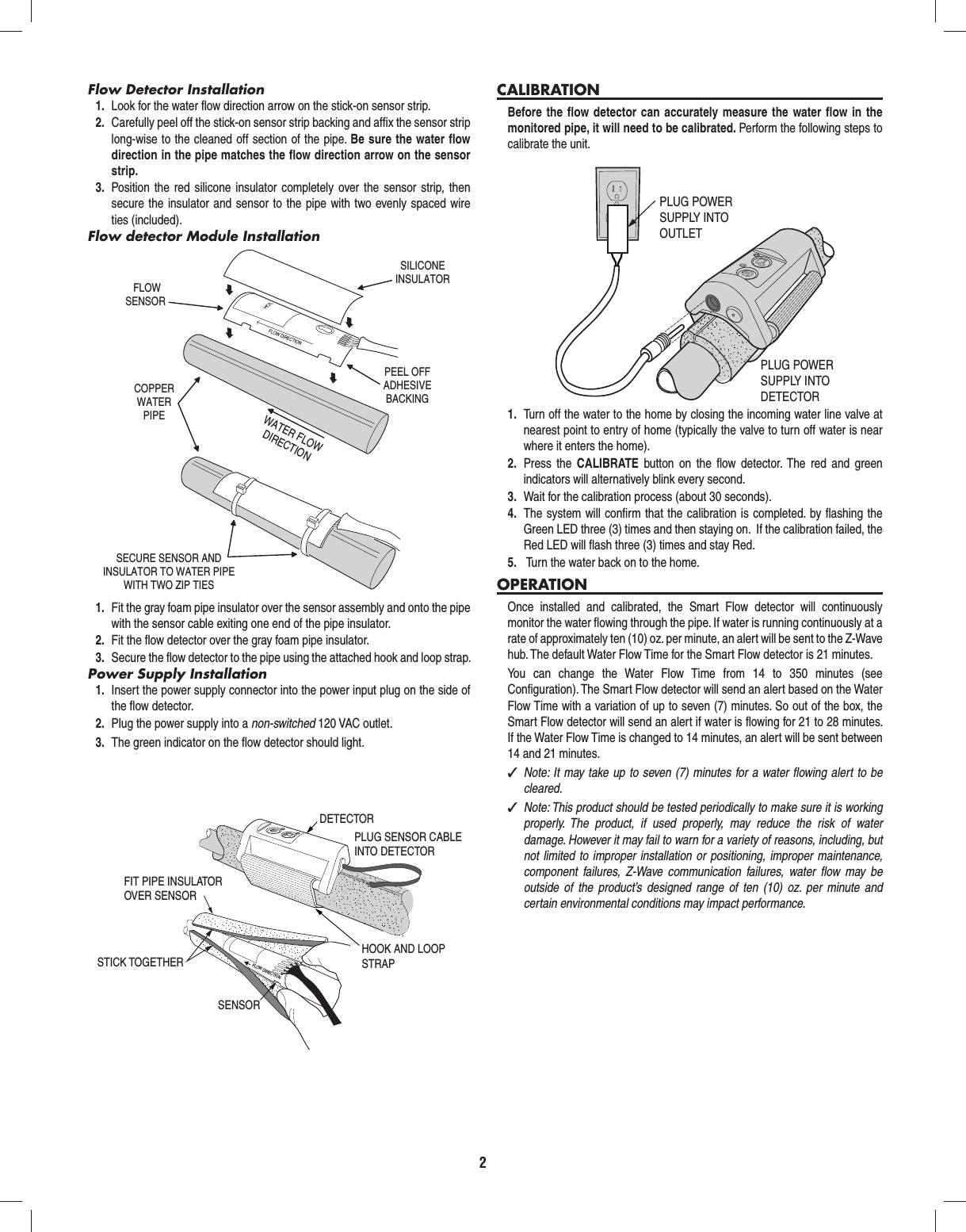
Nortek Security and Control 2GIG WL00Z1 Smart Water Flow Detector User Manual 10008194B WL00Z 1 Instructions indd

2GIG Technologies, Inc. Smart Water Flow Detector 10008194B WL00Z 1 Instructions indd

Users Manual

1GOCONTROL SMART Flow detectorThe GoControl™ family of Z-Wave® certifi ed wireless lighting products (smart LED bulbs, switches, dimmers, outlets, plug-in modules), security devices (alert sounder, motion sensor, and door/window sensor), and control products (garage door controller and thermostat) bring a new level of intelligent wireless capability to commercial and residential environments.The Z-Wave wireless protocol is an international wireless standard for remote home automation, security and other applications. Embedded in each device, the Z-Wave smart chip enables two-way RF communication among hundreds of Z-Wave enabled devices, allowing products and services from multiple manufacturers to work seamlessly.The FlowZ WL00Z-1 Smart Flow detector is simple to set up and provides whole house monitoring of water fl ow that can alert you to catastrophic water leaks like slab leaks, cracked pipes or a chronically running faucet.GoControl Z-Wave products are easy to install, are Z-Wave Plus certifi ed, and allow dealers to create an integrated wireless network with nearly limitless expansion and interoperability with security, energy management, home entertainment, appliances, and more.As part of a Z-Wave network, the WL00Z-1 will also act as a wireless repeater to insure that commands intended for another device in the network are received. This is useful when the device would otherwise be out of the radio range of the wireless controller.For indoor use only. Retain instructions for future use.Z-WAVE PLUS FEATURESThe WL00Z-1 contains a Z-Wave 500 Series Module that supports Z-Wave Plus® features. A Z-Wave certifi ed portable or stationary Controller can communicate with the Z-Wave 500 Series Module.Depending on the capability of the Controller or gateway software, the following operations will be performed by Smart Flow Detector. Refer to the controller or gateway manual for details.• Send an alert if water is running.• Add or Remove Smart Flow Detector. Over-the-air firmware update by thegateway or static Controller.• Lifeline function which automatically notifies the associated modules andthe network that a manually reset device is no longer in the network, thus,the corresponding association becomes invalid.INSTALLATIONThe WL00Z-1 Smart Flow detector module straps on a water pipe over the foam pipe insulator covering the stick-on sensor strip that directly contacts the pipe. The sensor strip that detects water fl ow plugs into the detector module. The detector module is powered by a UL Listed plug-in power supply that also plugs into the detector.Pipe Preparation1.  Examine the water piping of the installation. Find the incoming line fromthe meter or the line to be monitored. The WL00Z-1 must be installed indoors on a copper pipe 3/4 to 1”diameter. Monitoring of PVC,cast iron, galvanized or any other type of pipe is not supported.2.  Determine the direction of the water fl ow through the pipe to be monitored.3.  Clean a 6” section of the pipe with the included abrasive cleaning pad.To ensure good contact with the fl ow sensor, be sure to clean completelyaround the pipe.PRINTER’S INSTRUCTIONS:INSTR, INSTL, WL00Z-1, GO CONTROL; P/N: 10008194 B; INK: BLACK; MATERIAL: 20# MEAD BOND; SIZE: FLAT 17.000” x 11.000”, FOLDED 8.500” x 11.000”; TOLERANCE ± .125”; SCALE: 1-1WL00Z-1Z-Wave Radio Frequency (RF) Controlled Pipe Mounted Flow DetectorNOTE: This unit must be added to the Network only where it will be permanently installed. The proper operation of this node in the mesh network is dependent on it knowing its location with respect to other nodes. You cannot “test bench” confi gure this unit, then install.Z-Wave® and Z-Wave Plus® are registered trademarks of Sigma Designsand its subsidiaries in the United States and other countries.COPPERWATER PIPECLEAN A 6-INCH AREAOF THE WATER PIPEWHERE THE SENSOR STRIP WILL CONTACT THE PIPE6 INCHESCLEAN ALL THE WAYAROUND THE PIPEPIPE INSULATORCOPPER WATERSUPPLY PIPELEARN INDICATORWLOOZ-1 FLOWDETECTORCALIBRATE INDICATORLEARN BUTTONCALIBRATEBUTTONPLUG-INPOWERSUPPLYFLOW SENSOR STRIP
2Flow Detector Installation1.  Look for the water fl ow direction arrow on the stick-on sensor strip.2.  Carefully peel off the stick-on sensor strip backing and affi x the sensor strip long-wise to the cleaned off section of the pipe. Be sure the water fl ow direction in the pipe matches the fl ow direction arrow on the sensor strip.3.  Position the red silicone insulator completely over the sensor strip, then secure the insulator and sensor to the pipe with two evenly spaced wire ties (included).Flow detector Module Installation1.  Fit the gray foam pipe insulator over the sensor assembly and onto the pipe with the sensor cable exiting one end of the pipe insulator.2.  Fit the fl ow detector over the gray foam pipe insulator. 3.  Secure the fl ow detector to the pipe using the attached hook and loop strap.Power Supply Installation1.  Insert the power supply connector into the power input plug on the side of the fl ow detector.2.  Plug the power supply into a non-switched 120 VAC outlet.3.  The green indicator on the fl ow detector should light.CALIBRATIONBefore the fl ow detector can accurately measure the water fl ow in the monitored pipe, it will need to be calibrated. Perform the following steps to calibrate the unit.1.  Turn off the water to the home by closing the incoming water line valve at nearest point to entry of home (typically the valve to turn off water is near where it enters the home).2.  Press the CALIBRATE  button on the fl ow detector. The red and green  indicators will alternatively blink every second.3.  Wait for the calibration process (about 30 seconds).4.  The system will confi rm that the calibration is completed. by fl ashing the Green LED three (3) times and then staying on.  If the calibration failed, the Red LED will fl ash three (3) times and stay Red.5.   Turn the water back on to the home.OPERATIONOnce installed and calibrated, the Smart Flow detector will continuously monitor the water fl owing through the pipe. If water is running continuously at a rate of approximately ten (10) oz. per minute, an alert will be sent to the Z-Wave hub. The default Water Flow Time for the Smart Flow detector is 21 minutes.You can change the Water Flow Time from 14 to 350 minutes (see Confi guration). The Smart Flow detector will send an alert based on the Water Flow Time with a variation of up to seven (7) minutes. So out of the box, the Smart Flow detector will send an alert if water is fl owing for 21 to 28 minutes. If the Water Flow Time is changed to 14 minutes, an alert will be sent between 14 and 21 minutes. ✓Note: It may take up to seven (7) minutes for a water fl owing alert to be cleared. ✓Note: This product should be tested periodically to make sure it is working properly. The product, if used properly, may reduce the risk of water damage. However it may fail to warn for a variety of reasons, including, but not limited to improper installation or positioning, improper maintenance, component failures, Z-Wave communication failures, water fl ow may be outside of the product’s designed range of ten (10) oz. per minute and certain environmental conditions may impact performance.FLOWSENSORSILICONEINSULATORCOPPERWATERPIPEWATER FLOWDIRECTIONPEEL OFFADHESIVEBACKINGSECURE SENSOR ANDINSULATOR TO WATER PIPEWITH TWO ZIP TIESPLUG POWERSUPPLY INTOOUTLETPLUG POWERSUPPLY INTODETECTORHOOK AND LOOPSTRAPPLUG SENSOR CABLEINTO DETECTORDETECTORFLOW DIRECTIONFIT PIPE INSULATOROVER SENSOR STICK TOGETHERSENSOR
3e o t r n  e e y a e e r e . n e g r t , e d Z-WAVE PROGRAMMINGAdding to a Network:Refer to your Controller operating instructions to add this device under the command of the Wireless Controller.6.  With your Controller in Discovery or Add Mode, press the LEARN button. The green indicator will blink slowly.7.  When the Smart Flow Detector is added, the green indicator will blink quickly three times, then stay on.8.  You should see an indication on your Controller that the “device was added” to the network and the green indicator will turn off.9.  The device will appear in the list of sensors at the hub.If the Controller/Gateway shows the addition failed, the red indicator will fl ash three times then stay on. If this occurs, repeat Steps 1-3. ✓NOTE: If you have trouble adding the WL00Z-1 to a group it may be that the Home ID and Node ID were not cleared from it after testing. You must fi rst “RESET UNIT” to remove it from the network. Although adding it to a group includes it in the network, removing it from a group does not remove it from the network. If removed from a group, it functions as a repeater (only). “RESET UNIT” removes it completely from the network.To Reset Unit (If Required):In the event that your primary Controller is lost or otherwise inoperable, to reset the WL00Z-1 and clear all network information, follow these steps:1.  Press the LEARN button fi ve (5) times quickly. The green indicator will start to blink quickly.2.  Immediately press and hold the CALIBRATION button for 15 seconds.3.  The green indicator will turn off when the reset is successful.Removing from a Network:The WL00Z-1 can be removed from the network by the Controller/Gateway. Refer to the Controller operating instructions for details.1.  Set the Controller into Removal Mode.2.  Press the LEARN button.3.  The green indicator will begin to blink slowly. When the Smart Flow Detector  is successfully removed, the green indicator will blink quickly three times then stay on.4.  You should see an indication on your Controller that the device was removed from the network. ✓NOTE: If the Controller/Gateway shows the remove failed, the red indicator will fl ash three times and stay on. If this occurs, repeat Steps 1-3.CONFIGURATIONThe WL00Z-1 supports the Confi guration command. It can be confi gured to operate slightly differently than how it works when you fi rst install it.Using the Confi guration command you can confi gure the following:Flow Detection Alert TimingBy default, the WL00Z-1 will send an alert after approximately 21 minutes of continuous water fl ow.The length of time for continuous water fl ow before an alert is sent can be set to a minimum of 14 minutes and a maximum of 350 minutes by using the Confi guration Command Class, Parameter 0.By default, the WL00Z will send an alert when water is running from 21 to 27minutes.Parameter Length Valid Values Confi guration Option02 Bytes2 to 50 in whole number increments. Default =3Alert is sent when water is fl owing for x 7 + 7minutesAssociationsThe WL00Z-1 supports one level of Z-Wave association.Group 1 association is used to identify another Z-Wave device in the network that will receive unsolicited state changes and notifi cation (alarm) events.For instructions on how to “set lifeline association” please refer to your wireless controller instructions.INDICATOR LEGENDGREENINDICATORREDINDICATOR DESCRIPTIONSolid OffPowered on with no error conditions.(Note: the unit can be uncalibrated and/or unpaired in this state)Blinks every second OffIndicates the WL00Z-1 is in the process on Learning or Unlearning into a Z-Wave network.Fast blink (200ms) for 3 seconds, then SolidOff Indicates the WL00Z-1 succeeded Learning or Unlearning into a Z-Wave network.Super fast (100ms) blink OffThis is the result of tapping the Learn button 5 times within 2 seconds to initiate a Z-Wave reset of the WL00Z-1This is the fi rst step, the second step is to then hold down the Calibrate button for 15 seconds. If the Calibrate button is not held down during this state, it will end after 5 seconds.Solid Blink every second The WL00Z-1 detects water fl owing.Blink every 400ms, alternately with Red LEDBlink every 400ms, alternately with Green LEDIndicates the WL00Z-1is in the process of Calibration.Off SolidIndicates the last action performed by the WL00Z-1 failed. This can be Learn or Unlearn into the Z-Wave network, or a failed Calibration.Off Blink every secondThe WL00Z-1detects water fl owing, after the last action performed by the WL00Z-1 failed.OffFast blink (200ms) for 3 seconds, then SolidIndicates the WL00Z-1 failed Learning or Unlearning into a Z-Wave network.
SPECIFICATIONSPower:  120 VAC, 60 Hz Input, 14V 1700 mA Output Signal (Frequency):  908.42 MHz / 916 MHzRange:  Up to 130 feet line of sightREGULATORY INFORMATIONThe WL00Z-1 is certifi ed to comply with applicable FCC and IC rules and regulations governing RF and EMI emissions. This device complies with part 15 of the FCC Rules. Operation is subject to the following two conditions: (1) This device may not cause harmful interference, and (2) This device must accept any interference received, including interference that may cause undesired operation.FCC NoticeThis equipment has been tested and found to comply with the limits for a Class B digital device, pursuant to Part 15 of the FCC Rules. These limits are designed to provide reasonable protection against harmful interference in a residential installation.This equipment generates, uses, and can radiate radio frequency energy and, if not installed and used in accordance with the instructions may cause harmful interference to radio communications. However, there is no guarantee that interference will not occur in a particular installation. If this equipment does cause harmful interference to radio or television reception, which can be determined by turning the equipment off and on, the user is encouraged to try to correct the interference by one or more of the following measures:•  Reorient or relocate the receiving antenna.•  Increase the separation between the equipment and receiver•  Connect the equipment into an outlet on a circuit different from that to which the receiver is connected•  Consult the dealer or an experienced radio/TV technician to help.•  Changes or modifications not expressly approved by the party responsible for compliance could void the user’s authority to operate the equipmentIC NoticeThis Class B digital apparatus complies with Canadian ICES-003Cet appareil numérique de la classe B est conforme à la norme NMB-003 du Canada. Le présent appareil est conforme aux CNR d’Industrie Canada applicables aux appareils radio exempts de licence. L’exploitation est autorisée aux deux conditions suivantes : (1) l’appareil ne doit pas produire de brouillage, et (2) l’utilisateur de l’appareil doit accepter tout brouillage radioélectrique subi, même si le brouillage est susceptible d’en compromettre le fonctionnement.This device complies with the Industry Canada license exempt RSS standard(s). Operation is subject to the following two conditions: (1) this device may not cause interference, and (2) this device must accept any interference, including interference that may cause undesired operation of the device.WARRANTYWhat is Covered?Nortek Security & Control (“NS&C”) warrants to consumers who purchase this product for personal, family or household purposes new from NS&C directly or from an authorized NS&C dealer, that the product will be free from defects in materials and workmanship for a period of (1) year from the date of purchase. This warranty only applies if the product is installed at a residence in the 50 United States or District of Columbia, and only at the site of the original installation. It is not transferable. This warranty is not extended to resellers.If a defect exists, NS&C will have you ship the defective part or product to us and we will, at our option, either repair or replace it. This warranty does not cover the cost of labor to remove a defective part or product or to reinstall any repaired or replacement part or product.This warranty does not cover defects or damages caused by improper handling, maintenance, storage, installation, removal or re-installation, misuse, non-factory authorized modifi cation or alteration, use of incompatible accessories, electrical power problems or surges, impact by foreign objects, accident, fi re, acts of God, normal wear and tear or shipping damage other than a shipment from NS&C.  Note that all NS&C products are designed to be installed, removed and serviced by trained individuals or professionals.Keep your original sales receipt as it will be required to obtain warranty service.This warranty shall not be extended or restarted upon receipt of any repaired or replacement part or product under this warranty. No person is authorized to extend or otherwise modify this warranty.How do I Obtain Warranty Service?To obtain warranty service, email our Returns Department at returns@nortek.com. Include your name, address, telephone number, the model number of your product, a copy of your original sales receipt, and a description of the problem. Unless we need to discuss the situation further with you, you will be emailed a Return Authorization Number and shipping instructions. If we need to discuss the situation further with you, we will call or email you. NS&C may require troubleshooting on installed product before a Return Authorization Number is issued. Anything shipped to us without a Return Authorization Number will be automatically returned unopened. You are responsible for the charges for shipment to us, unless you are a California resident.LimitationsTHE DURATION OF ANY IMPLIED WARRANTY, INCLUDING THE WARRANTIES OF MERCHANTABILITY AND FITNESS FOR A PARTICULAR PURPOSE, SHALL NOT EXCEED THE WARRANTY PERIOD PROVIDED HEREIN.Some states do not allow limitations on how long an implied warranty lasts, so the above limitation may not apply to you.NS&C SHALL NOT BE LIABLE FOR ANY INCIDENTAL OR CONSEQUENTIAL DAMAGES RESULTING FROM THE BREACH OF ANY WRITTEN OR IMPLIED WARRANTY.Some states do not allow the exclusion or limitation of incidental or consequential damages, so the above limitation or exclusion may not apply to you.This warranty gives you specifi c legal rights, and you may also have other legal rights which vary from State to State.IMPORTANT !!!Radio controls provide a reliable communications link and fi ll an important need in portable wireless signaling. However, there are some limitations which must be observed.•  For U.S. installations only: The radios are required to comply with FCC Rules and Regulations as Part 15 devices. As such, they have limited transmitter power and therefore limited range.•  A receiver cannot respond to more than one transmitted signal at a time and may be blocked by radio signals that occur on or near their operating frequencies, regardless of code settings.•  Changes or modifications to the device may void FCC compliance.•  Infrequently used radio links should be tested regularly to protect against undetected interference or fault.•  A general knowledge of radio and its vagaries should be gained prior to acting as a wholesale distributor or dealer, and these facts should be communicated to the ultimate users. Copyright © 2016 Nortek Security & Control LLC  10008194 B

Navigation menu