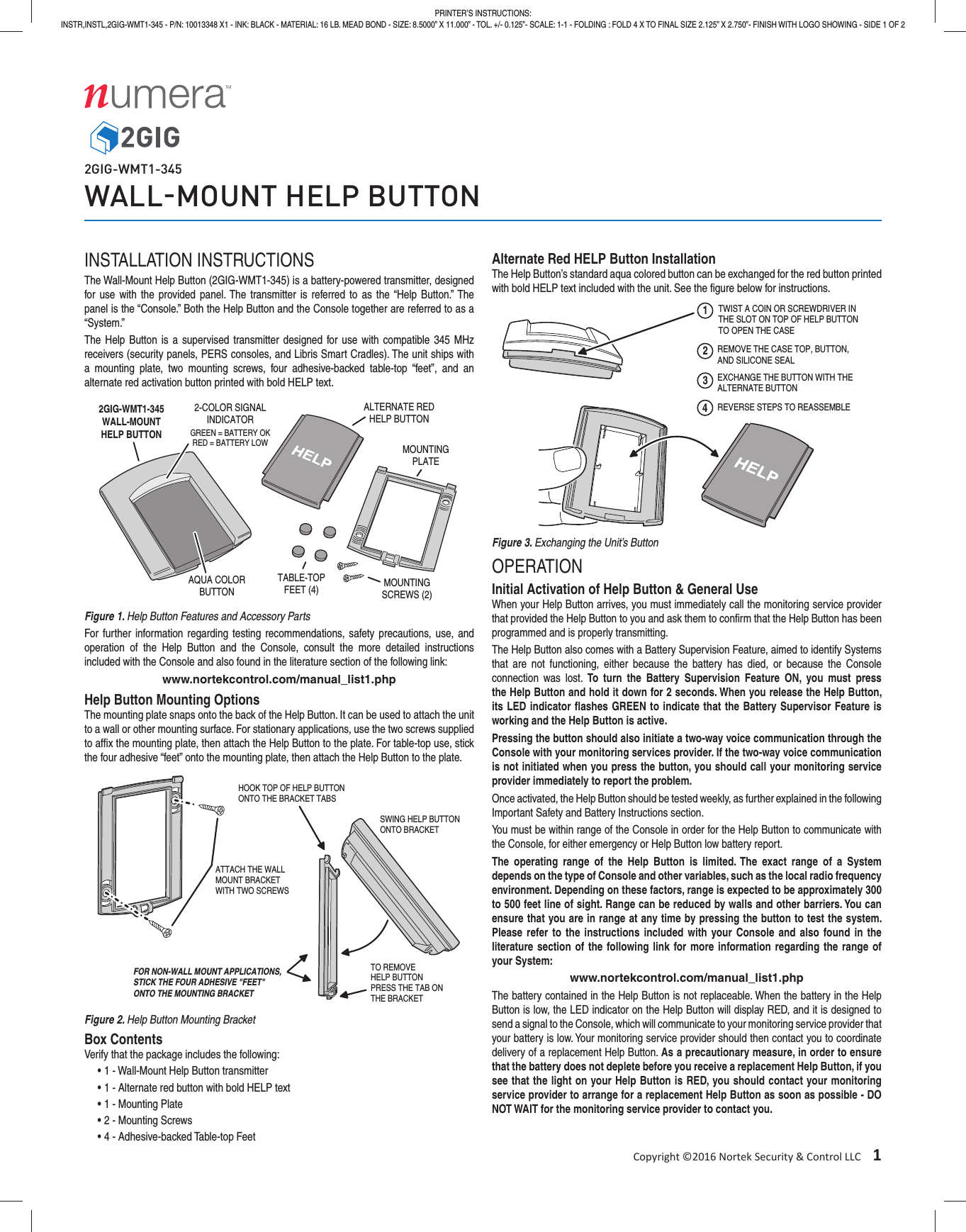
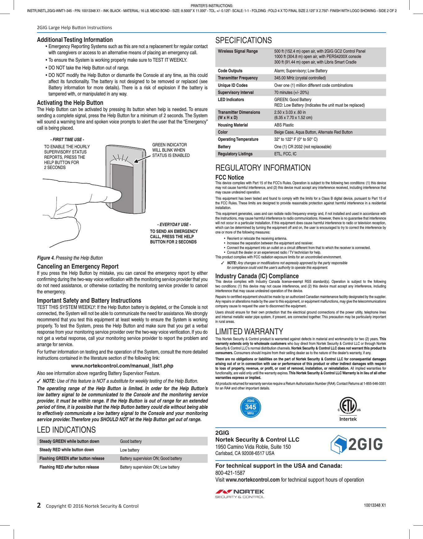
Nortek Security and Control 2GIG WMT1345 Wall-Mount Help Button User Manual 10013348A indd

2GIG Technologies, Inc. Wall-Mount Help Button 10013348A indd

Users Manual

Copyright ©2016 Nortek Security & Control LLC 1PRINTER’S INSTRUCTIONS:INSTR,INSTL,2GIG-WMT1-345 - P/N: 10013348 X1 - INK: BLACK - MATERIAL: 16 LB. MEAD BOND - SIZE: 8.5000” X 11.000” - TOL. +/- 0.125”- SCALE: 1-1 - FOLDING : FOLD 4 X TO FINAL SIZE 2.125” X 2.750”- FINISH WITH LOGO SHOWING - SIDE 1 OF 22GIG-WMT1-345WALLMOUNT HELP BUTTONINSTALLATION INSTRUCTIONSThe Wall-Mount Help Button (2GIG-WMT1-345) is a battery-powered transmitter, designed for use with the provided panel. The transmitter is referred to as the “Help Button.” The panel is the “Console.” Both the Help Button and the Console together are referred to as a “System.”The Help Button is a supervised transmitter designed for use with compatible 345 MHz receivers (security panels, PERS consoles, and Libris Smart Cradles). The unit ships with a mounting plate, two mounting screws, four adhesive-backed table-top “feet”, and an alternate red activation button printed with bold HELP text.Figure 1. Help Button Features and Accessory PartsFor further information regarding testing recommendations, safety precautions, use, and operation of the Help Button and the Console, consult the more detailed instructions included with the Console and also found in the literature section of the following link: www.nortekcontrol.com/manual_list1.phpHelp Button Mounting OptionsThe mounting plate snaps onto the back of the Help Button. It can be used to attach the unit to a wall or other mounting surface. For stationary applications, use the two screws supplied to affi x the mounting plate, then attach the Help Button to the plate. For table-top use, stick the four adhesive “feet” onto the mounting plate, then attach the Help Button to the plate.Figure 2. Help Button Mounting BracketBox ContentsVerify that the package includes the following:• 1 - Wall-Mount Help Button transmitter• 1 - Alternate red button with bold HELP text• 1 - Mounting Plate• 2 - Mounting Screws• 4 - Adhesive-backed Table-top FeetAlternate Red HELP Button InstallationThe Help Button’s standard aqua colored button can be exchanged for the red button printed with bold HELP text included with the unit. See the fi gure below for instructions.Figure 3. Exchanging the Unit’s ButtonOPERATIONInitial Activation of Help Button & General UseWhen your Help Button arrives, you must immediately call the monitoring service provider that provided the Help Button to you and ask them to confi rm that the Help Button has been programmed and is properly transmitting.The Help Button also comes with a Battery Supervision Feature, aimed to identify Systems that are not functioning, either because the battery has died, or because the Console connection was lost. To turn the Battery Supervision Feature ON, you must press the Help Button and hold it down for 2 seconds. When you release the Help Button, its LED indicator fl ashes GREEN to indicate that the Battery Supervisor Feature is working and the Help Button is active.Pressing the button should also initiate a two-way voice communication through the Console with your monitoring services provider. If the two-way voice communication is not initiated when you press the button, you should call your monitoring service provider immediately to report the problem.Once activated, the Help Button should be tested weekly, as further explained in the following Important Safety and Battery Instructions section.You must be within range of the Console in order for the Help Button to communicate with the Console, for either emergency or Help Button low battery report.The operating range of the Help Button is limited. The exact range of a System depends on the type of Console and other variables, such as the local radio frequency environment. Depending on these factors, range is expected to be approximately 300 to 500 feet line of sight. Range can be reduced by walls and other barriers. You can ensure that you are in range at any time by pressing the button to test the system. Please refer to the instructions included with your Console and also found in the literature section of the following link for more information regarding the range of your System:www.nortekcontrol.com/manual_list1.phpThe battery contained in the Help Button is not replaceable. When the battery in the Help Button is low, the LED indicator on the Help Button will display RED, and it is designed to send a signal to the Console, which will communicate to your monitoring service provider that your battery is low. Your monitoring service provider should then contact you to coordinate delivery of a replacement Help Button. As a precautionary measure, in order to ensure that the battery does not deplete before you receive a replacement Help Button, if you see that the light on your Help Button is RED, you should contact your monitoring service provider to arrange for a replacement Help Button as soon as possible - DO NOT WAIT for the monitoring service provider to contact you.2GIG-WMT1-345WALL-MOUNTHELP BUTTON2-COLOR SIGNALINDICATORAQUA COLORBUTTONMOUNTINGPLATETABLE-TOPFEET (4) MOUNTINGSCREWS (2)ALTERNATE REDHELP BUTTONGREEN = BATTERY OKRED = BATTERY LOWATTACH THE WALLMOUNT BRACKETWITH TWO SCREWSHOOK TOP OF HELP BUTTONONTO THE BRACKET TABSSWING HELP BUTTONONTO BRACKETTO REMOVEHELP BUTTONPRESS THE TAB ONTHE BRACKETFOR NON-WALL MOUNT APPLICATIONS,STICK THE FOUR ADHESIVE "FEET"ONTO THE MOUNTING BRACKET12TWIST A COIN OR SCREWDRIVER INTHE SLOT ON TOP OF HELP BUTTONTO OPEN THE CASEREMOVE THE CASE TOP, BUTTON,AND SILICONE SEAL3EXCHANGE THE BUTTON WITH THEALTERNATE BUTTON4REVERSE STEPS TO REASSEMBLE
2 Copyright © 2016 Nortek Security & ControlAdditional Testing Information• Emergency Reporting Systems such as this are not a replacement for regular contact with caregivers or access to an alternative means of placing an emergency call.• To ensure the System is working properly make sure to TEST IT WEEKLY.• DO NOT take the Help Button out of range.• DO NOT modify the Help Button or dismantle the Console at any time, as this could affect its functionality. The battery is not designed to be removed or replaced (see Battery information for more details). There is a risk of explosion if the battery is tampered with, or manipulated in any way.Activating the Help ButtonThe Help Button can be activated by pressing its button when help is needed. To ensure sending a complete signal, press the Help Button for a minimum of 2 seconds. The System will sound a warning tone and spoken voice prompts to alert the user that the “Emergency” call is being placed.Figure 4. Pressing the Help ButtonCanceling an Emergency ReportIf you press the Help Button by mistake, you can cancel the emergency report by either confi rming during the two-way voice verifi cation with the monitoring service provider that you do not need assistance, or otherwise contacting the monitoring service provider to cancel the emergency.Important Safety and Battery InstructionsTEST THIS SYSTEM WEEKLY: If the Help Button battery is depleted, or the Console is not connected, the System will not be able to communicate the need for assistance. We strongly recommend that you test this equipment at least weekly to ensure the System is working properly. To test the System, press the Help Button and make sure that you get a verbal response from your monitoring service provider over the two-way voice verifi cation. If you do not get a verbal response, call your monitoring service provider to report the problem and arrange for service. For further information on testing and the operation of the System, consult the more detailed instructions contained in the literature section of the following link:www.nortekcontrol.com/manual_list1.phpAlso see information above regarding Battery Supervisor Feature. ✓NOTE: Use of this feature is NOT a substitute for weekly testing of the Help Button.The operating range of the Help Button is limited. In order for the Help Button’s low battery signal to be communicated to the Console and the monitoring service provider, it must be within range. If the Help Button is out of range for an extended period of time, it is possible that the Help Button battery could die without being able to effectively communicate a low battery signal to the Console and your monitoring service provider. Therefore you SHOULD NOT let the Help Button get out of range.LED INDICATIONSSteady GREEN while button down Good batterySteady RED while button down Low batteryFlashing GREEN after button release Battery supervision ON; Good batteryFlashing RED after button release Battery supervision ON; Low batterySPECIFICATIONSWireless Signal Range 500 ft (152.4 m) open air, with 2GIG GC2 Control Panel1000 ft (304.8 m) open air, with PERS4200X console300 ft (91.44 m) open air, with Libris Smart CradleCode Outputs Alarm; Supervisory; Low BatteryTransmitter Frequency 345.00 MHz (crystal controlled)Unique ID Codes Over one (1) million different code combinationsSupervisory Interval 70 minutes (+/- 20%)LED Indicators GREEN: Good BatteryRED: Low Battery (Indicates the unit must be replaced)Transmitter Dimensions(W x H x D)2.50 x 3.03 x .60 in(6.35 x 7.70 x 1.52 cm)Housing Material ABS PlasticColor Beige Case, Aqua Button, Alternate Red ButtonOperating Temperature 32° to 122° F (0° to 50° C)Battery One (1) CR 2032 (not replaceable)Regulatory Listings ETL, FCC, ICREGULATORY INFORMATIONFCC NoticeThis device complies with Part 15 of the FCC’s Rules. Operation is subject to the following two conditions: (1) this device may not cause harmful interference, and (2) this device must accept any interference received, including interference that may cause undesired operation.This equipment has been tested and found to comply with the limits for a Class B digital device, pursuant to Part 15 of the FCC Rules. These limits are designed to provide reasonable protection against harmful interference in a residential installation.This equipment generates, uses and can radiate radio frequency energy and, if not installed and used in accordance with the instructions, may cause harmful interference to radio communications. However, there is no guarantee that interference will not occur in a particular installation. If this equipment does cause harmful interference to radio or television reception, which can be determined by turning the equipment off and on, the user is encouraged to try to correct the interference by one or more of the following measures:•  Reorient or relocate the receiving antenna.•  Increase the separation between the equipment and receiver.•  Connect the equipment into an outlet on a circuit different from that to which the receiver is connected.•  Consult the dealer or an experienced radio / TV technician for help.This product complies with FCC radiation exposure limits for an uncontrolled environment. ✓NOTE: Any changes or modifi cations not expressly approved by the party responsible for compliance could void the user’s authority to operate this equipment.Industry Canada (IC) ComplianceThis device complies with Industry Canada license-exempt RSS standard(s). Operation is subject to the following two conditions: (1) this device may not cause interference, and (2) this device must accept any interference, including interference that may cause undesired operation of the device.Repairs to certifi ed equipment should be made by an authorized Canadian maintenance facility designated by the supplier. Any repairs or alterations made by the user to this equipment, or equipment malfunctions, may give the telecommunications company cause to request the user to disconnect the equipment.Users should ensure for their own protection that the electrical ground connections of the power utility, telephone lines and internal metallic water pipe system, if present, are connected together. This precaution may be particularly important in rural areas.LIMITED WARRANTYThis Nortek Security & Control product is warranted against defects in material and workmanship for two (2) years. This warranty extends only to wholesale customers who buy direct from Nortek Security & Control LLC or through Nortek Security & Control LLC’s normal distribution channels. Nortek Security & Control LLC does not warrant this product to consumers. Consumers should inquire from their selling dealer as to the nature of the dealer’s warranty, if any.There are no obligations or liabilities on the part of Nortek Security & Control LLC for consequential damages arising out of or in connection with use or performance of this product or other indirect damages with respect to loss of property, revenue, or profi t, or cost of removal, installation, or reinstallation. All implied warranties for functionality, are valid only until the warranty expires. This Nortek Security & Control LLC Warranty is in lieu of all other warranties express or implied.All products returned for warranty service require a Return Authorization Number (RA#). Contact Returns at 1-855-546-3351 for an RA# and other important details.MHz2GIG3452GIG Large Help Bu on Instruc ons10013348 X1PRINTER’S INSTRUCTIONS:INSTR,INSTL,2GIG-WMT1-345 - P/N: 10013348 X1 - INK: BLACK - MATERIAL: 16 LB. MEAD BOND - SIZE: 8.5000” X 11.000” - TOL. +/- 0.125”- SCALE: 1-1 - FOLDING : FOLD 4 X TO FINAL SIZE 2.125” X 2.750”- FINISH WITH LOGO SHOWING - SIDE 2 OF 22GIGNortek Security & Control LLC1950 Camino Vida Roble, Suite 150Carlsbad, CA 92008-6517 USAFor technical support in the USA and Canada:800-421-1587Visit www.nortekcontrol.com for technical support hours of operationTO ENABLE THE HOURLYSUPERVISORY STATUSREPORTS, PRESS THEHELP BUTTON FOR2 SECONDSGREEN INDICATORWILL BLINK WHENSTATUS IS ENABLEDTO SEND AN EMERGENCYCALL, PRESS THE HELPBUTTON FOR 2 SECONDS- FIRST TIME USE -- EVERYDAY USE -

Navigation menu