Novra Technologies S750100 Digital Satellite Receiver User Manual Novra S50 Receiver
Novra Technologies Inc. Digital Satellite Receiver Novra S50 Receiver
UserManual.wiki
>
Novra Technologies
>
S750100 User Manual
Manual
Navigation menu
Upload a User Manual
Namespaces
Wiki Guide
HTML
PDF
Info
Views
User Manual
Discussion / Help
Navigation
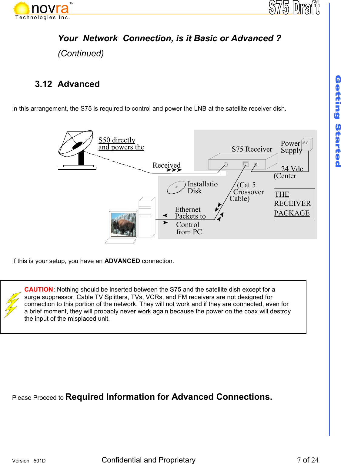
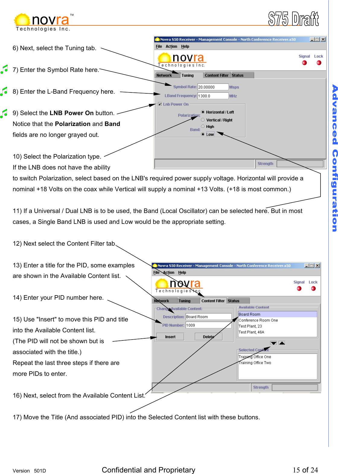
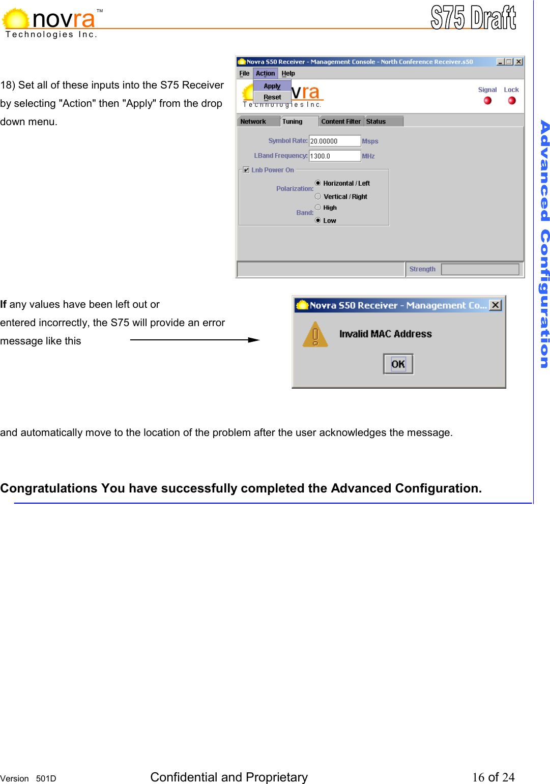
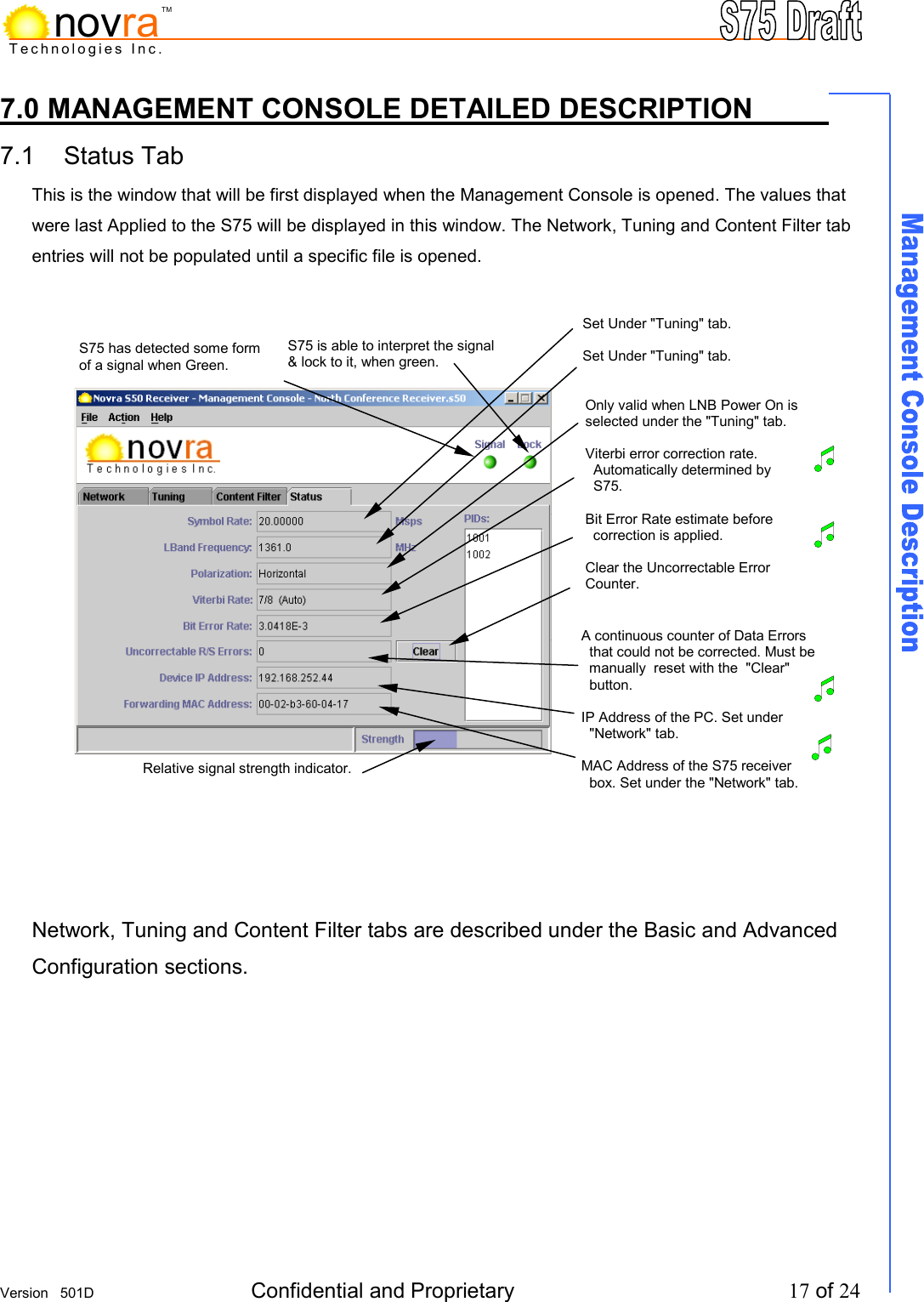
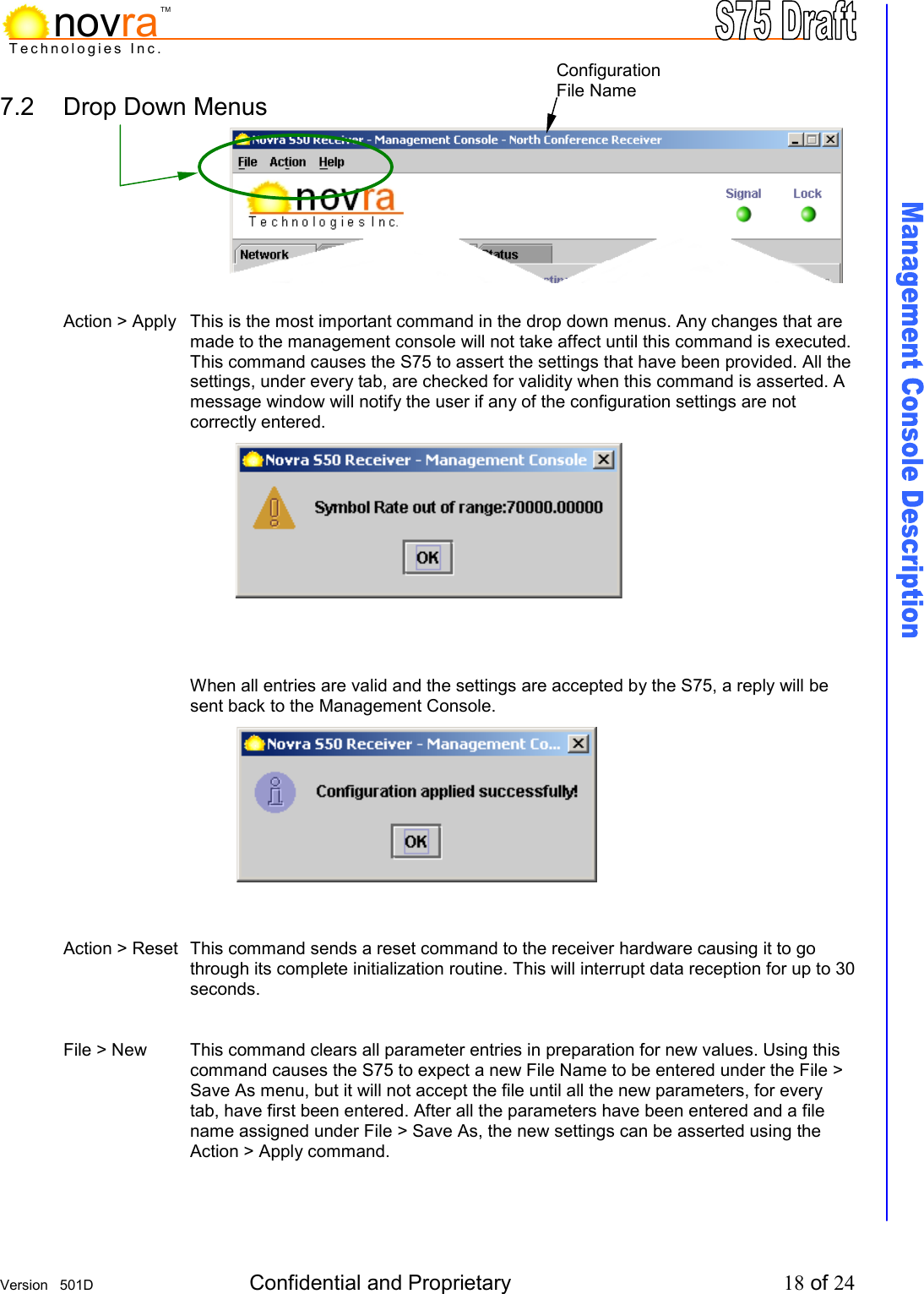
![Version 501D Confidential and Proprietary 2 of 24 Technologies Inc.novraTM Novra S75 Receiver, User Manual Subject to change without notification Document version: 501D ________________________________ Important- Please read this entire manual before installing or operating this product. ________________________________ Disclaimer While reasonable effort has been made in the preparation of this document to assure its accuracy, Novra Technologies Inc. assumes no responsibility for errors or omissions that may appear in this manual. Novra reserves the right to change the contents of this manual at any time without notice. Acknowledgements This product uses parts of the iMatix SFL, Copyright © 1991-2000 iMatix Corporation http://www.imatix.com This product incorporates the CPSLAPI Version 0.5.1 [Licensed under GNU LGPL V2 (GNU Library General Public License)] This product uses parts of the 1.3.0 release of the Common C++ class library which is licensed under the GNU General Public License with the exception that software linked with the Common C++ and other files to produce an executable, does not cause the resulting executable to be covered by the GNU General Public License. This product includes software developed by the Politecnico di Torino, and its contributors. Copyright © 2001 Novra Technologies Inc. All rights reserved. Information in this manual is subject to change without notice. No part of this manual may be reproduced or transmitted in any form, by photocopy, microfilm, xerography, or any other means, or incorporated into any information retrieval system, electronic or mechanical, for any purpose, without the express written permission of Novra Technologies Inc. Regulatory Compliance Novra Technologies Inc. is in the process of gaining FCC certification for this device. This certification is not currently complete.](https://usermanual.wiki/Novra-Technologies/S750100/User-Guide-255038-Page-2.png)