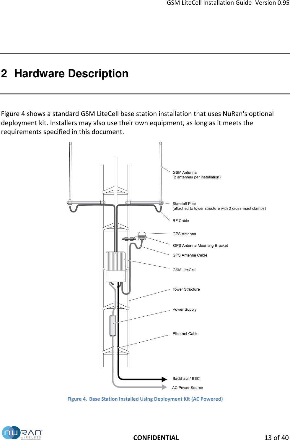
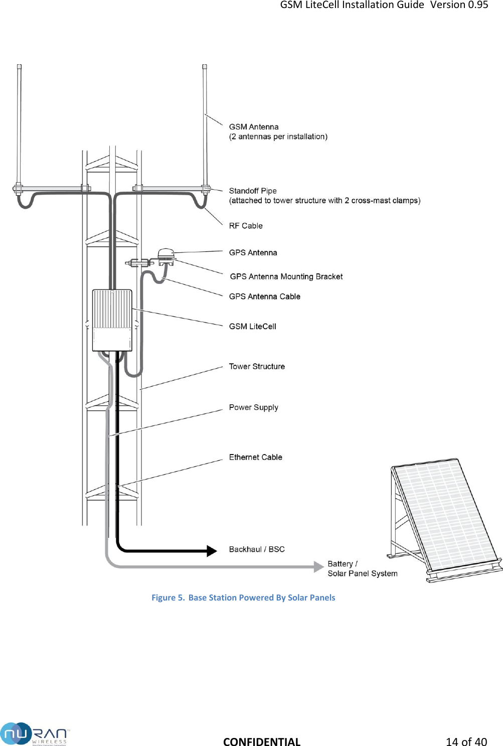
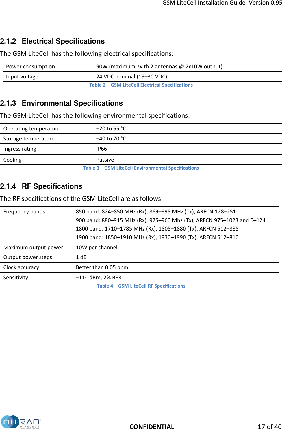
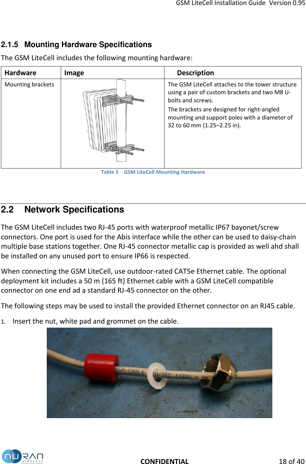
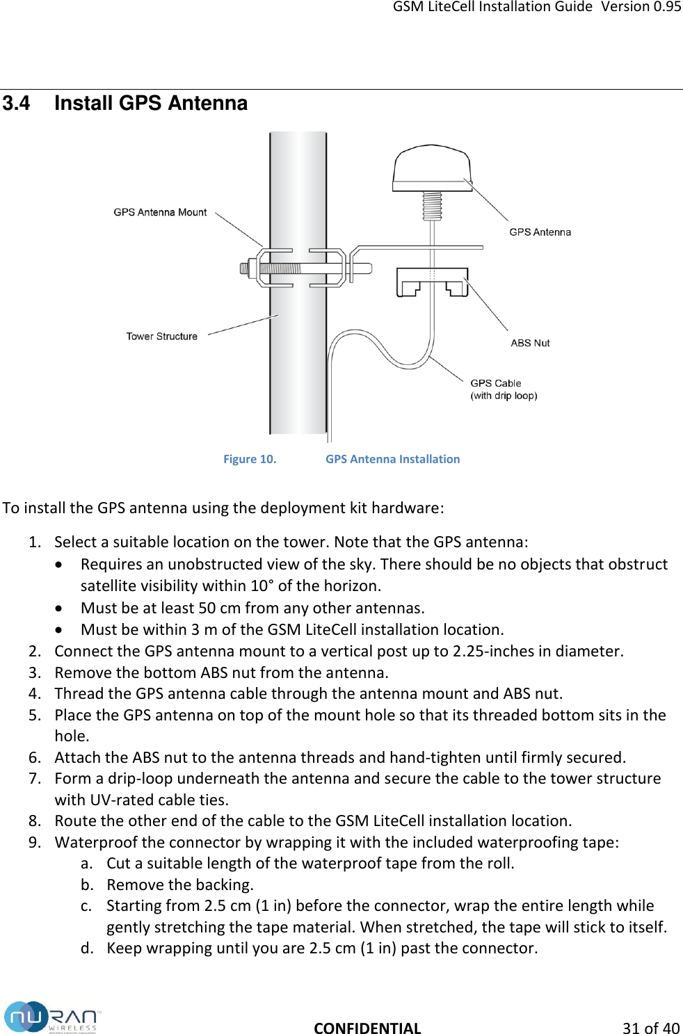
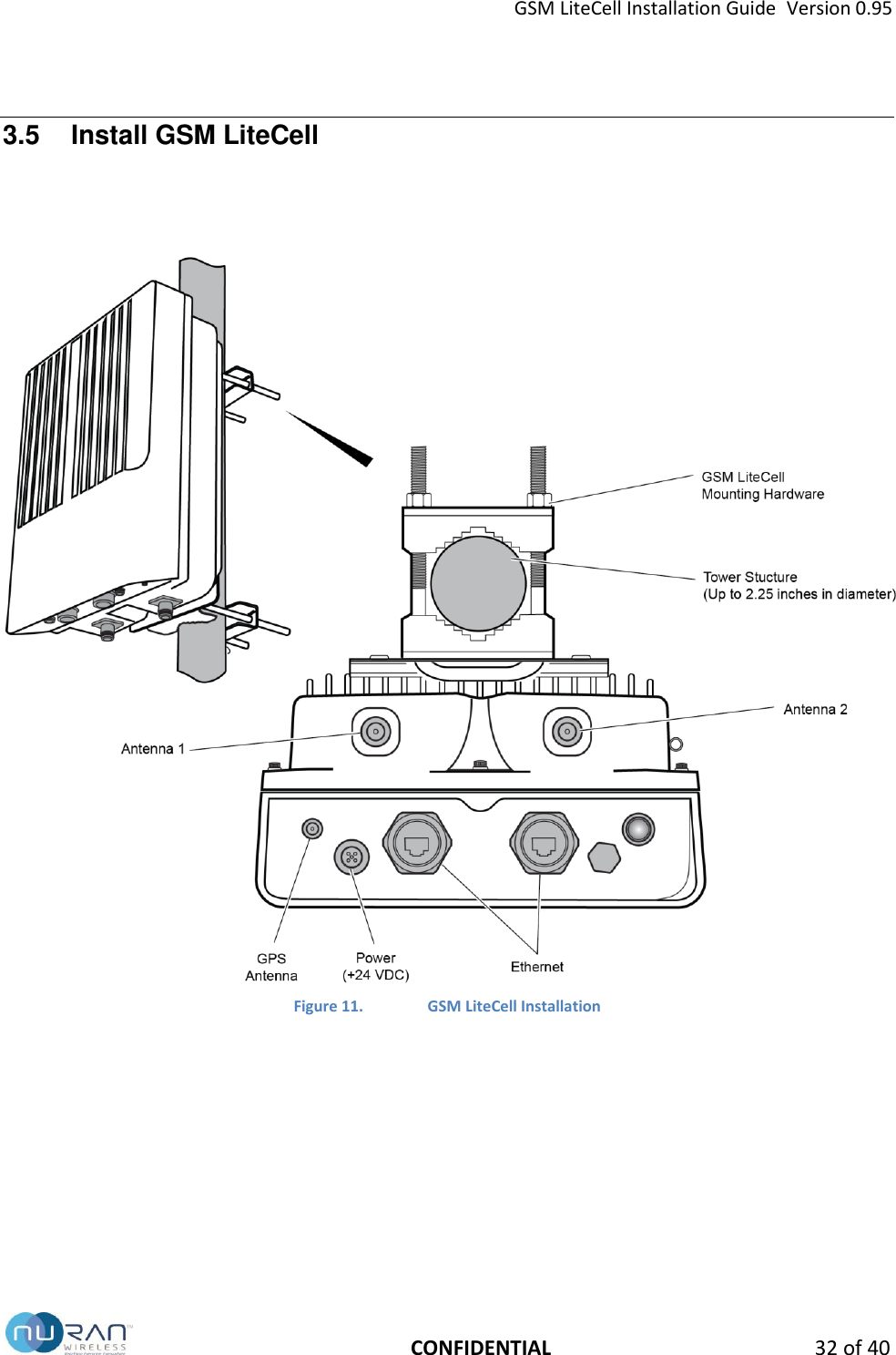
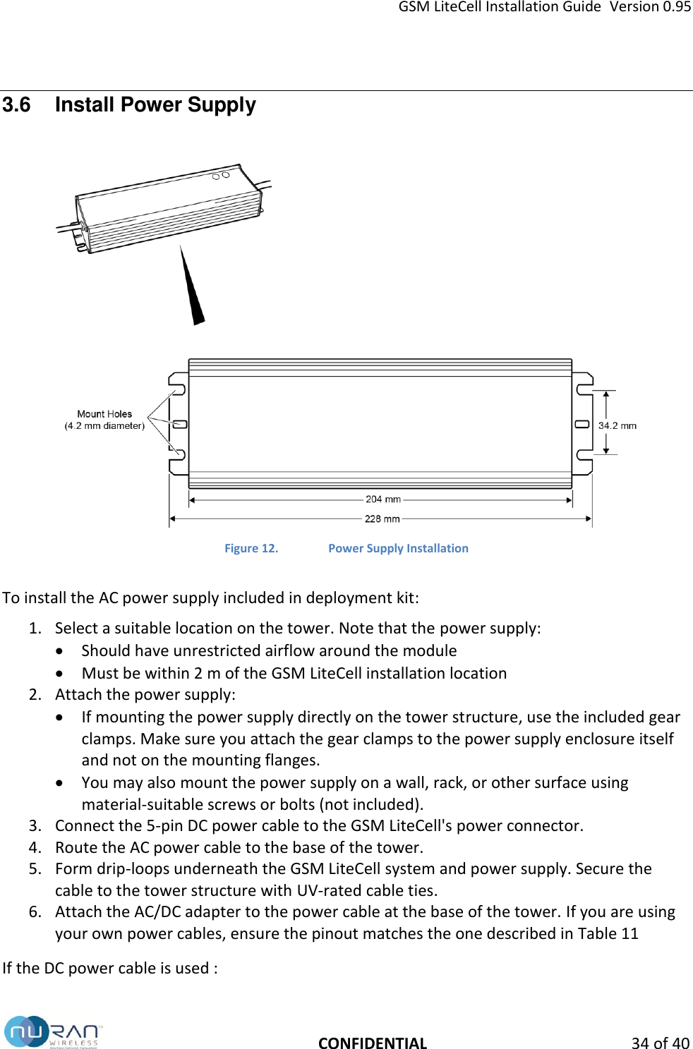
Nuran Wireless GSM310-850 GSM Base Station User Manual GSM LiteCell Installation Guide
Nuran Wireless GSM Base Station GSM LiteCell Installation Guide
UserManual.wiki
>
Nuran Wireless
>
GSM310 850 User Manual
Users Manual
Navigation menu
Upload a User Manual
Namespaces
Wiki Guide
HTML
PDF
Info
Views
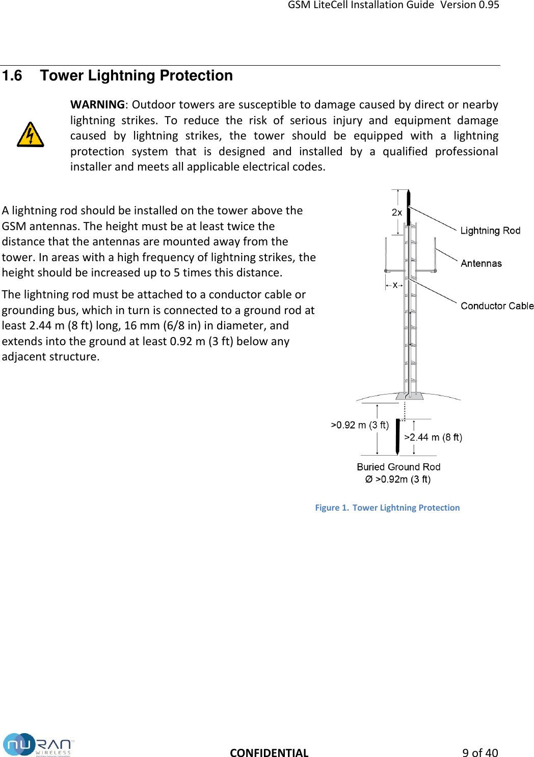
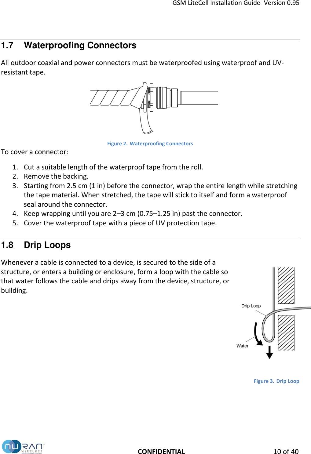
User Manual
Discussion / Help
Navigation