ORBCOMM License ST6000 Mobile Satellite Earth Station Module User Manual T407 ST 6000 Hardware Guide
ORBCOMM License Corp. Mobile Satellite Earth Station Module T407 ST 6000 Hardware Guide
UserManual.wiki
>
ORBCOMM License
>
ST6000 User Manual
Users Manual
Navigation menu
Upload a User Manual
Namespaces
Wiki Guide
HTML
PDF
Info
Views
User Manual
Discussion / Help
Navigation


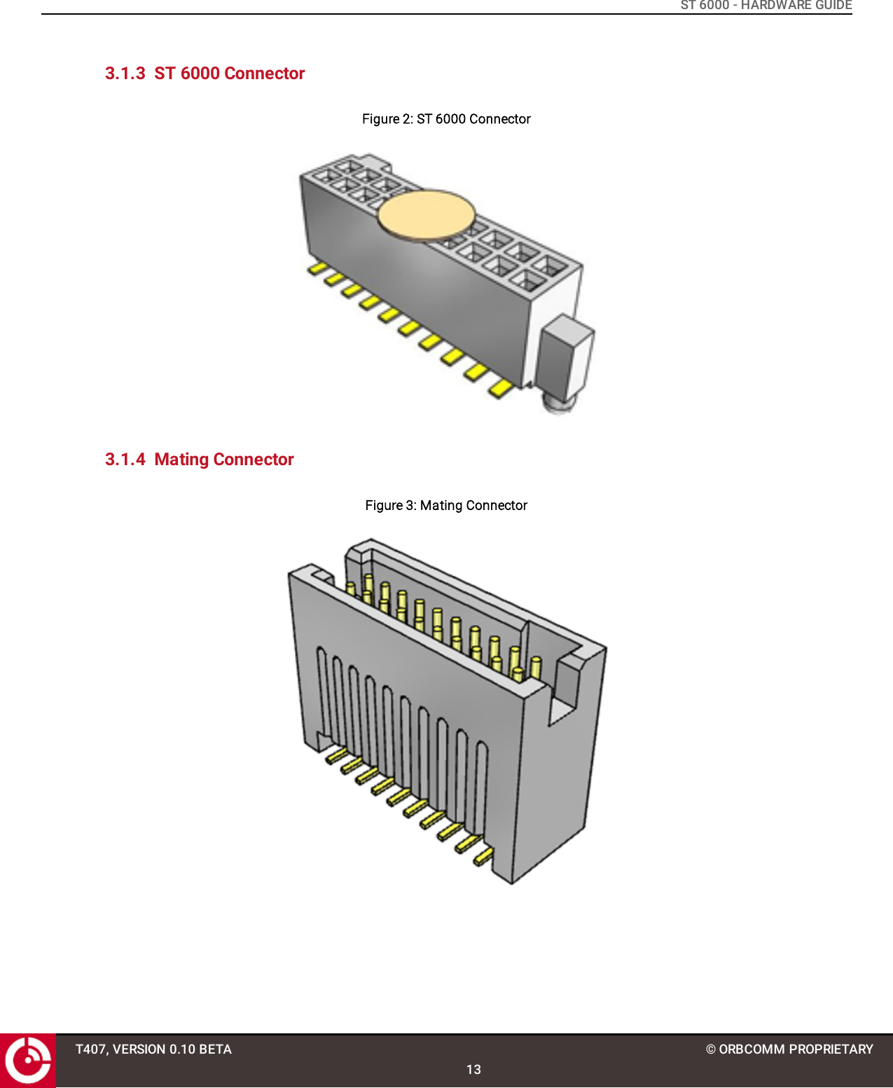
![ST 6000 - HARDWARE GUIDEPREFACEPurposeThis document provides an overview of the hardware characteristics and specifications for the 20-pin ST 6000.NotationAn OEM Integrator is an ORBCOMM customer who purchases an ST 6000 for integration into their own enclosure. Tobecome an OEM Integrator certain commercial criteria must be met. Contact your Account Executive for furtherdetails.Hardware components and hardware stickers in this document might not be exactly as shown and are subject tochange without notice.CAUTION: This safety symbol warns of possible hazards to personnel, equipment, or both. It includeshazards that will or can cause personal injury, property damage, or death if the hazard is notavoided.Note: A note indicates information with no potential hazard. A note indicates points of interest or providessupplementary information about a feature or task.Numbered lists indicate a series of steps required to complete a task or function.Bulleted lists highlight information where order or sequence is not crucial.ReferenceThe content of the following documents may be useful in conjunction with this guide. These documents areavailable from the ORBCOMM Developer Toolkit (hereafter referred to as the Toolkit) or customer support.[T404] LSF Developer Guide for FW v3.x[T405] IsatData Pro Service API Reference for FW v3.xT407, VERSION 0.10 BETA8© ORBCOMM PROPRIETARY](https://usermanual.wiki/ORBCOMM-License/ST6000/User-Guide-3665883-Page-8.png)
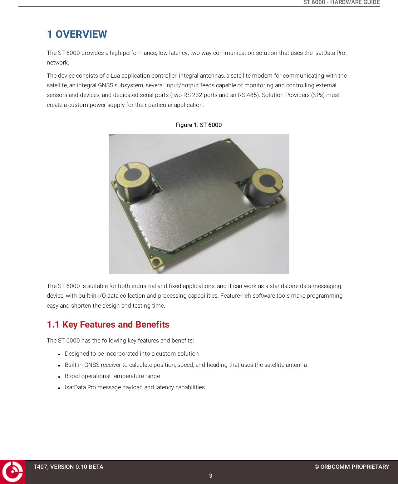

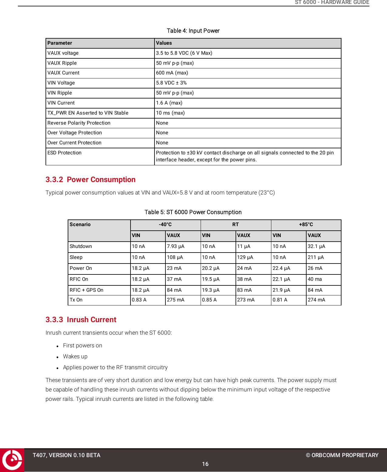
![ST 6000 - HARDWARE GUIDE3.2 AntennaThe ST 6000 supports two standard onboard antennas: Main and Diversity. Refer to [T406] for general antennaspecifications.Figure 4: Onboard Antennas3.3 Power3.3.1 Input PowerThe ST 6000 has two power input pins (VAUX and VIN), and can be powered from either a single or dual external DCpower source.VAUX supplies power to the ST 6000 baseband and RF processors. Regulated power must be applied to this pincontinuously to keep the device alive and synchronized with the satellite network.VIN is the input power pin for the RF power amplifier circuitry. Regulated power must be applied to this pin wheneverthe device drives the TX_PWR EN line high and may be removed when the TX_PWR EN line is low. Alternatively, powermay be applied to this pin continuously and TX_PWR_EN ignored.Note: Input power protection is not provided on the ST 6000.T407, VERSION 0.10 BETA15© ORBCOMM PROPRIETARY](https://usermanual.wiki/ORBCOMM-License/ST6000/User-Guide-3665883-Page-15.png)

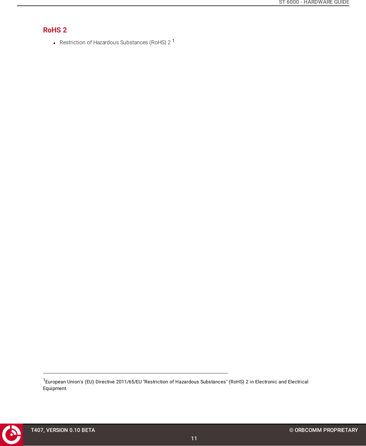
![ST 6000 - HARDWARE GUIDE3.5.2 RS-485/J1708 InterfaceThe ST 6000 has a dedicated TTL level serial port for interfacing to an RS-485/J1708 interface as an accessory busand for SCADA interfacing. The ST 6000 does not incorporate a driver and termination resistor. The RS-485 serial portis connected directly to the UART of the microcontroller and therefore communicates via 3.3 V CMOS levels.3.6 Accelerometer/GNSS/Temperature SensorThe ST 6000 supports an accelerometer, a multi-GNSS module, and a temperature sensor. Refer to [T406] for details.3.7 RF Specifications3.7.1 FrequencyParameter ValueReceiveFrequency Band 1525 to 1559 MHzModulation OQPSKSymbol Rate 3000 symbols/secondsPolarization RHCPTransmitFrequency Band 1626.5 to 1660.5 MHzModulation OQPSKSymbol Rate 900 symbols/seconds (maximum)Polarization RHCPParameter ValueMaximum EIRP 7 dBWElevation Angle 0 to 90 degreesMaximum transmit antenna gain 3.9 dBic3.8 GNSSThe manufacturer's specifications are given in the table below.T407, VERSION 0.10 BETA19© ORBCOMM PROPRIETARYTypical Output Power 1.5WWARNING: Please keep the device minimum 20cm away from human body 3.7.2 Antenna](https://usermanual.wiki/ORBCOMM-License/ST6000/User-Guide-3665883-Page-19.png)

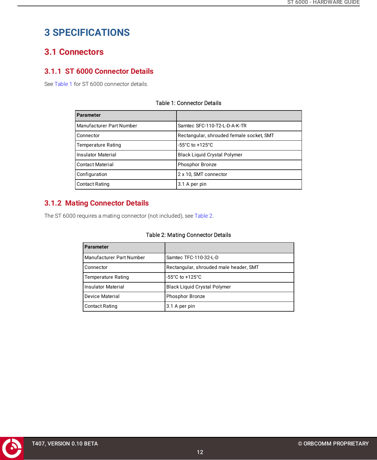
![ST 6000 - HARDWARE GUIDEFigure 5: Accelerometer AxisThe accelerometer is very important for low power devices when it is critical to save power while stationary andquickly detect when motion starts. In powered devices where low power is not critical, GPS can be polled to detectmotion. However, for low power applications frequent GPS fixes can dominate the power budget. To reduce powerbudget effects of GPS fixes, an accelerometer can be used to trigger a GPS fix to detect if motion occurred.The accelerometer thresholds to detect motion vary depending on the environment. In order to avoid, false motiondetects, extensive testing is required to ensure that adequate acceleration magnitude thresholds and time durationsare used. Refer to [T405] for further details about the accelerometer.Table 11: Accelerometer SpecificationsParameter Condition Min. Typical Max. UnitsResolution 2 g - 3.91 - mGTracking software selectable - ±2 - g- ±4 - g- ±8 - g- ±16 - gBandwidth Filtering Selectable via digital interface 8 - 1000 HzSensitivity 2 g - 256 - LSB/g4 g - 128 - LSB/g8 g - 64 - LSB/g16 g - 32 - LSB/gT407, VERSION 0.10 BETA21© ORBCOMM PROPRIETARY](https://usermanual.wiki/ORBCOMM-License/ST6000/User-Guide-3665883-Page-21.png)
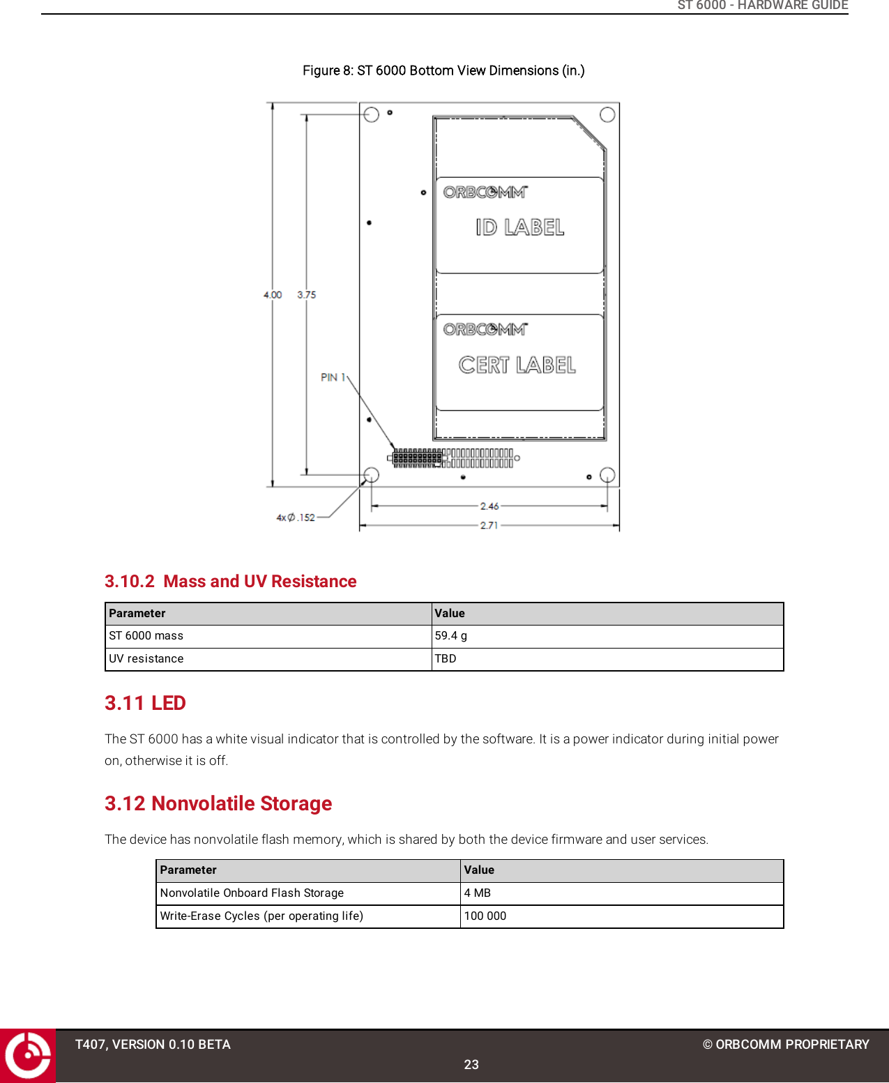
![ST 6000 - HARDWARE GUIDEIf using the accelerometer, mount the device in one of the configurations shown in [T405].3.10 Mechanical3.10.1 DimensionsFigure 6: ST 6000 Top ViewFigure 7: ST 6000 Side View Dimensions (in.)T407, VERSION 0.10 BETA22© ORBCOMM PROPRIETARY](https://usermanual.wiki/ORBCOMM-License/ST6000/User-Guide-3665883-Page-22.png)