Omron 6CYAIDV7000100 RF-ID System User Manual V700HMC 7173 Manual 2000 7
Omron Corporation RF-ID System V700HMC 7173 Manual 2000 7
UserManual.wiki
>
Omron
>
6CYAIDV7000100 User Manual
>
Manual HMC71 and 73
Contents
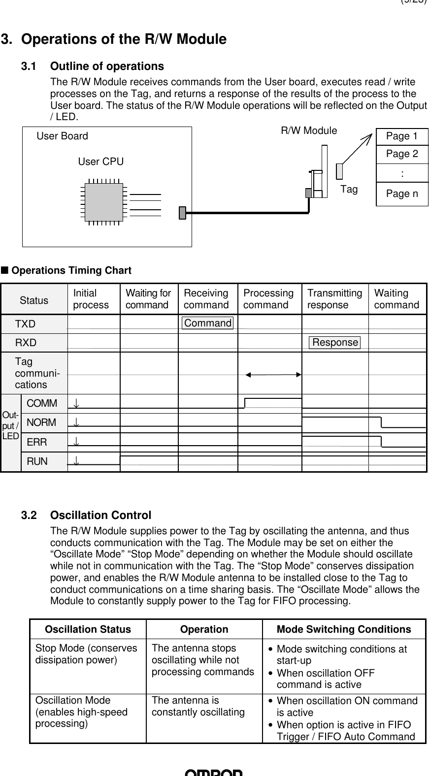
1.
Manual HMC71 and 73
2.
Manual HMD11
Manual HMC71 and 73
Navigation menu
Upload a User Manual
Namespaces
Wiki Guide
HTML
PDF
Info
Views
User Manual
Discussion / Help
Navigation
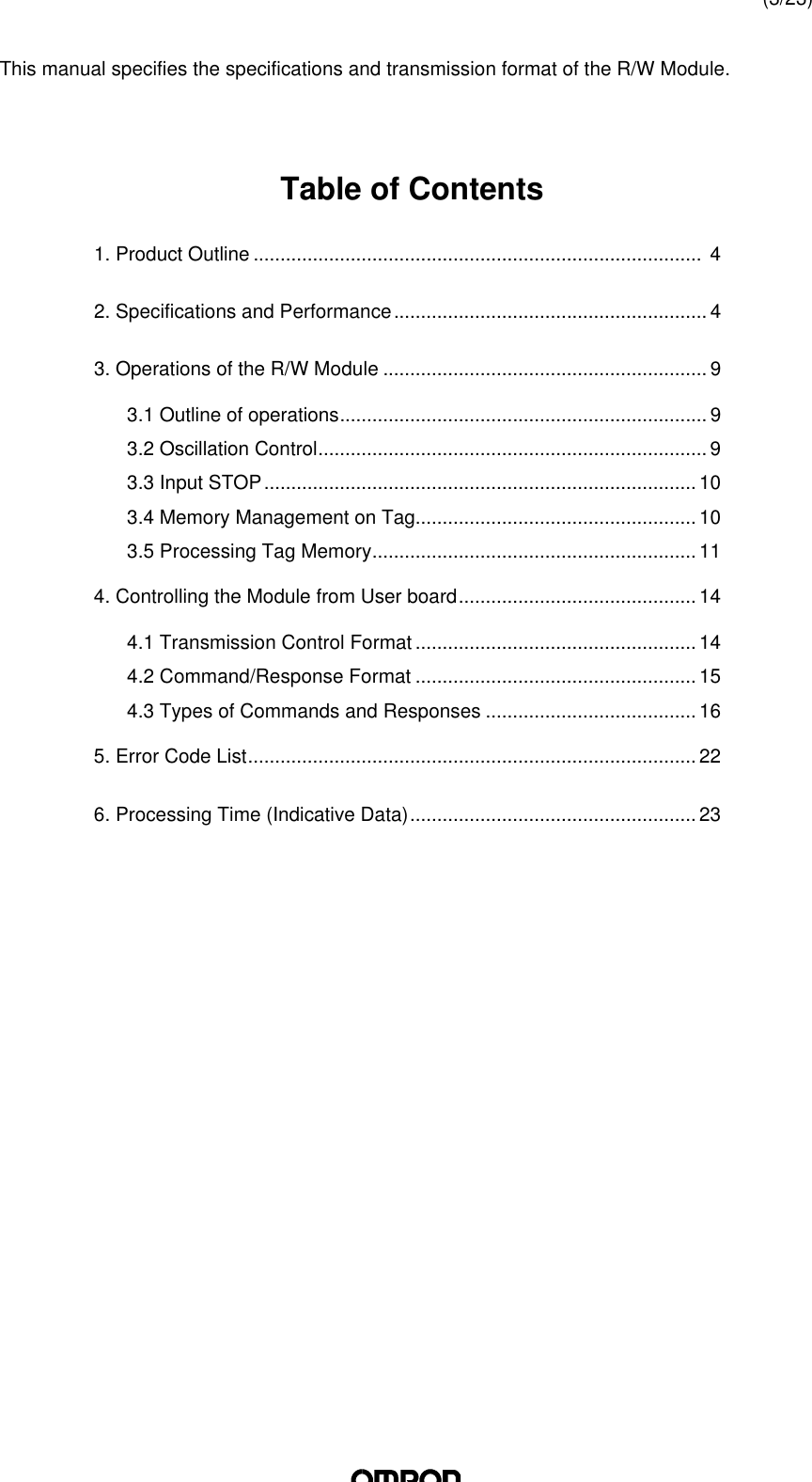
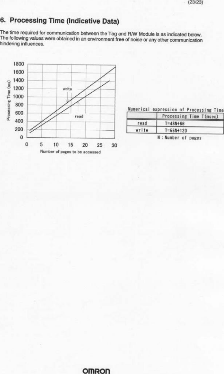
![(13/23)4) FIFO AutoModule will await Tag to approach after receiving command, thencommunicate with Tag and transmit response. After communication iscompleted, Module will prohibit Tag from operating. Module will be on standby after response transmission is completed. During communication withthe Tag, there MUST BE AN OPERATIONAL TAG (A TAG THAT IS NOTPROHIBITED FROM OPERATION) within the communication area. Whenthis command is executed, Module automatically activates “OscillationMode.”♦ Operation SequenceAfter receiving command, the Module waits for the Tag to approach, thenexecutes process once only after Tag is detected. During processing of thecommand, Tag will become inoperative, and thus will not respond to thenext command. Oscillation will continue after command is processed.When Module receives a STOP command, the command will becompleted.5) FIFO ContinueAfter receiving command, the Module waits for the Tag to approach, thencommunicates with the Tag and transmits a response. After communicationis completed, Tag will become inoperative. After transmitting a response,Module will await Tag to approach again if it receives [ACK], andCONTINUE UNTIL MODULE RECEIVES A STOP COMMAND. Whencommunicating with the Tag, THERE MUST ONLY BE ONE ACTIVE TAGwithin the communication area.♦ Operation SequenceUpon receiving the command, Module awaits Tag to approach. When Tagis detected, Module executes command and transmits a response.Afterwards, when [ACK] is received, Module repeats the same operation.Once process is executed on a Tag, the Tag becomes inoperative, and thusa Tag will only be processed once. When Module receives a STOPcommand, processing will stop.(Oscillation)Tag 1Command CommandResponseSTOPResponse 11TagCommunicationTag OperationUser ←User →Tag DetectionTagDetectionCommand Process(TruncationProcess)(Oscillation)Tag 2Tag 1Command STOPNACKACKResponse 2Response 2Response 1TagDetectionTagDetectionTagCommunicationTag OperationUser ←User →Command ProcessCommand Process(Oscillation)](https://usermanual.wiki/Omron/6CYAIDV7000100.Manual-HMC71-and-73/User-Guide-109337-Page-13.png)
![(14/23)6) FIFO RepeatAfter receiving command, the Module waits for the Tag to approach, thencommunicates with the Tag and transmits a response. After communicationis completed, Tag will become inoperative. MODULE WILL CONTINUEPROCESS UNTIL IT RECEIVES A STOP COMMAND. Whencommunicating with the Tag, THERE MUST ONLY BE ONE ACTIVE TAG(A TAG THAT IS NOT PROHIBITED FROM OPERATION) within thecommunication area.♦ Operation SequenceUpon receiving the command, Module awaits Tag to approach. When Tagis detected, Module executes command and transmits a response.Afterwards, Module repeats the same operation. Once process is executedon a Tag, the Tag becomes inoperative, and thus a Tag will only beprocessed once. When Module receives a STOP command, processing willstop.4. Controlling the Module from User board4.1 Transmission Control FormatThe frame format consists of 16 types of text in even number units from through “0”~“F” (Band the terminator [Cr] (ASCII code : 0Dh). Text TerminatorCrData Number ofcharacters DetailsText 1 ~ 272 Parameters of each command (“0” ~ “F”)Terminator 1Code (0Dh) indicating the completion of transmissionframe(Transmission Control Procedure)Receipt commences when a character is received first, and when [Cr] is received,the frame is recognized as finished. If the interval between data exceeds 2 seconds,a transmission error will be recognized.272 characters or lessTagDetectionTagDetectionTagDetectionTagDetectionSTOPCommandResponse 3ResponsResponse 2(TruncationProcess)Command ProcessCommandCommandResponse 1Tag 3Tag 2Tag 1TagCommunicationTag OperationUser ←User →](https://usermanual.wiki/Omron/6CYAIDV7000100.Manual-HMC71-and-73/User-Guide-109337-Page-14.png)