Omron 6CYCIDV6400304 RF ID Transmitter User Manual users manual
Omron Corporation RF ID Transmitter users manual
UserManual.wiki
>
Omron
>
6CYCIDV6400304 User Manual
users manual
Navigation menu
Upload a User Manual
Namespaces
Wiki Guide
HTML
PDF
Info
Views
User Manual
Discussion / Help
Navigation
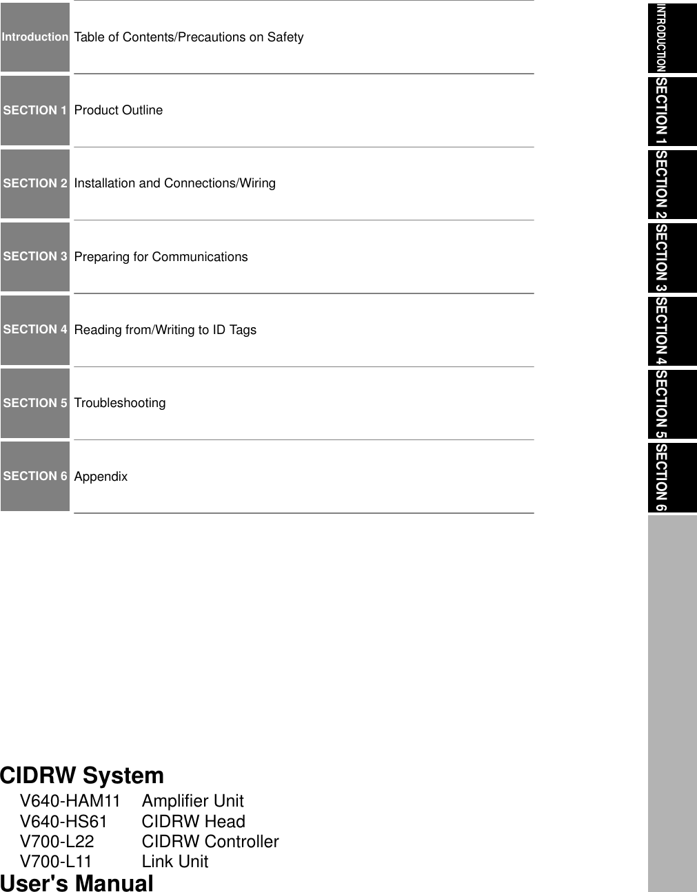
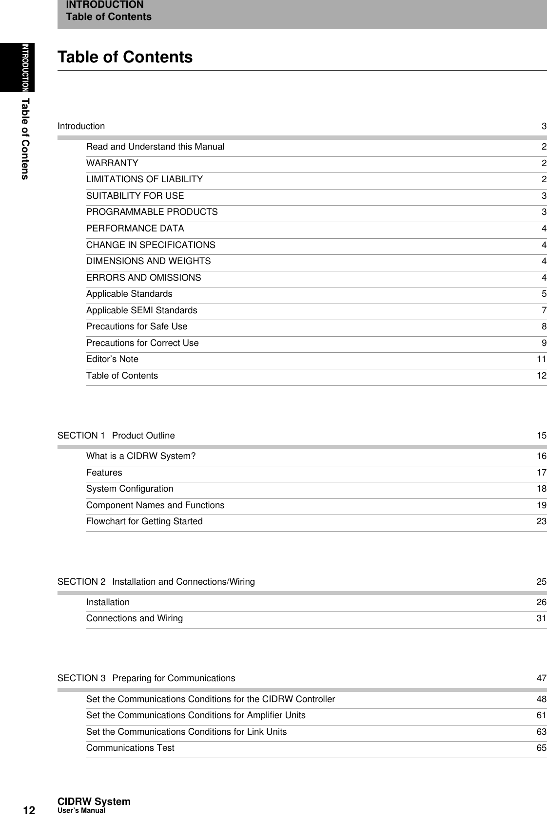
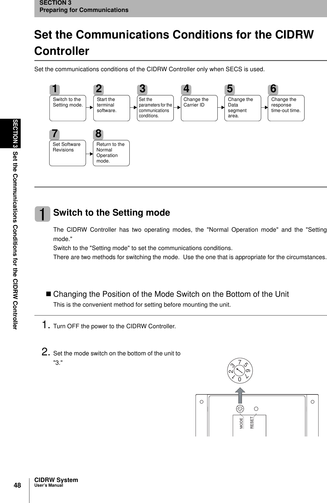
![5CIDRW SystemUser’s ManualINTRODUCTIONPrecautions for Safe UseINTRODUCTIONApplicable Standards1. FCC Rules (Federal Communications Commission)This device complies with Part 15 Subpart C of the FCC Rules.FCC ID: E4E6CYCID6400202Operation is subject to the following two conditions:(1) this device may not cause harmful interference, and (2) this device must accept any interference received, including interference that may cause undesired oper-ation.FCC NOTICEThis equipment has been tested and found to comply with the limits for a Class B digital device, pursu-ant to part 15 of the FCC Rules. These limits are designed to provide reasonable protection againstharmful interference in a residential installation.This equipment generates, uses and can radiate radio frequency energy and, if not installed and usedin accordance with the instructions, may cause harmful interference to radio communications. How-ever, there is no guarantee that interference will not occur in a particular installation. If this equipmentdoes cause harmful interference to radio or television reception, which can be determined by turningthe equipment off and on, the user is encouraged to try to correct the interference by one or more ofthe following measures: • Reorient or relocate the receiving antenna• Increase the separation between the equipment and receiver.• Connect the equipment into an outlet on a circuit different from that to which the receiver isconnected.• Consult the dealer or an experienced radio/TV technician for help. FCC WARNINGChanges or modifications not expressly approved by the party responsible for compliance could voidthe user's authority to operate the equipment.Properly shielded and grounded cables and connectors must be used for connection to hostcomputer and/or peripherals in order to meet FCC emission limits.CAUTIONThis device must be professionally installed.This CIDRW Head [Model: V640-HS61 (-X)] is dedicated to Amplifier Unit [Model: V640-HAM11 (-X)]. E4E6CYCIDV6400304Do not remove the ferrite core on the cable of the CIDRW head.](https://usermanual.wiki/Omron/6CYCIDV6400304/User-Guide-486045-Page-5.png)

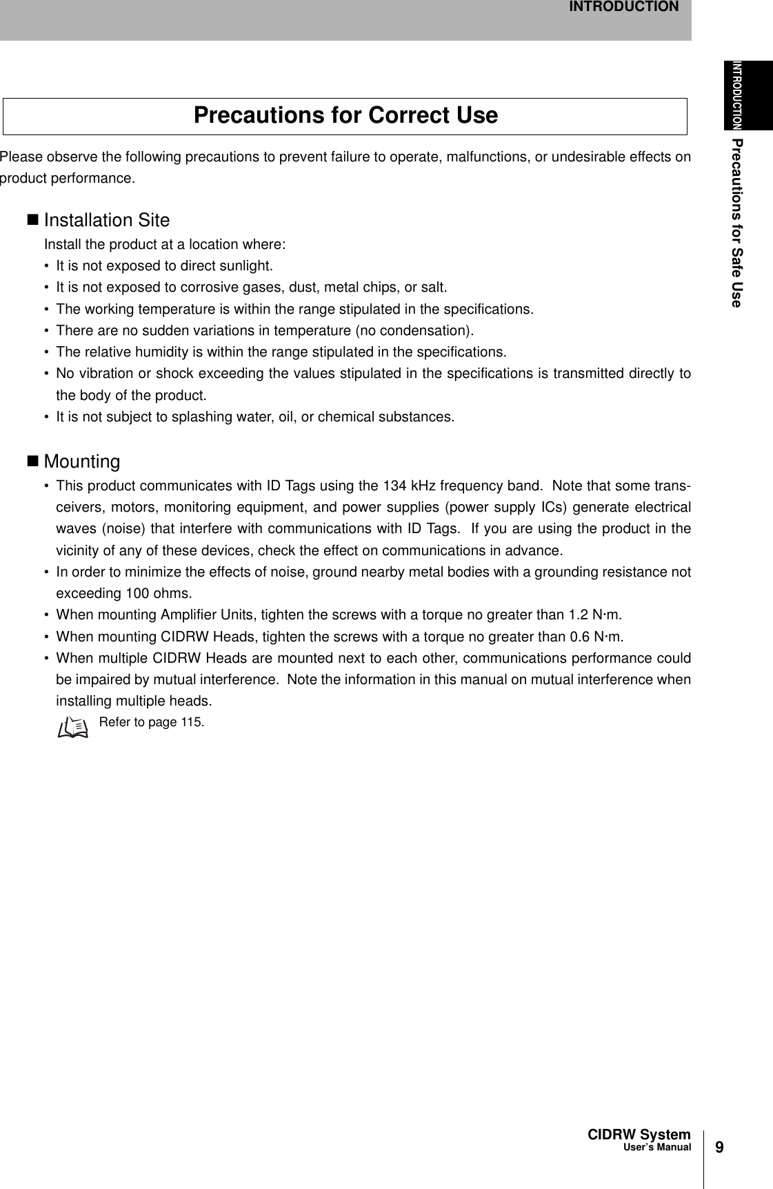
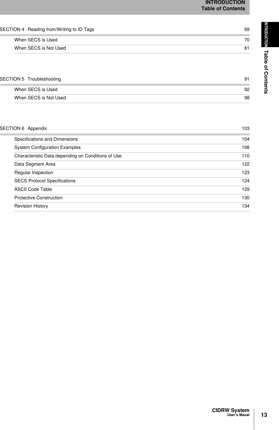
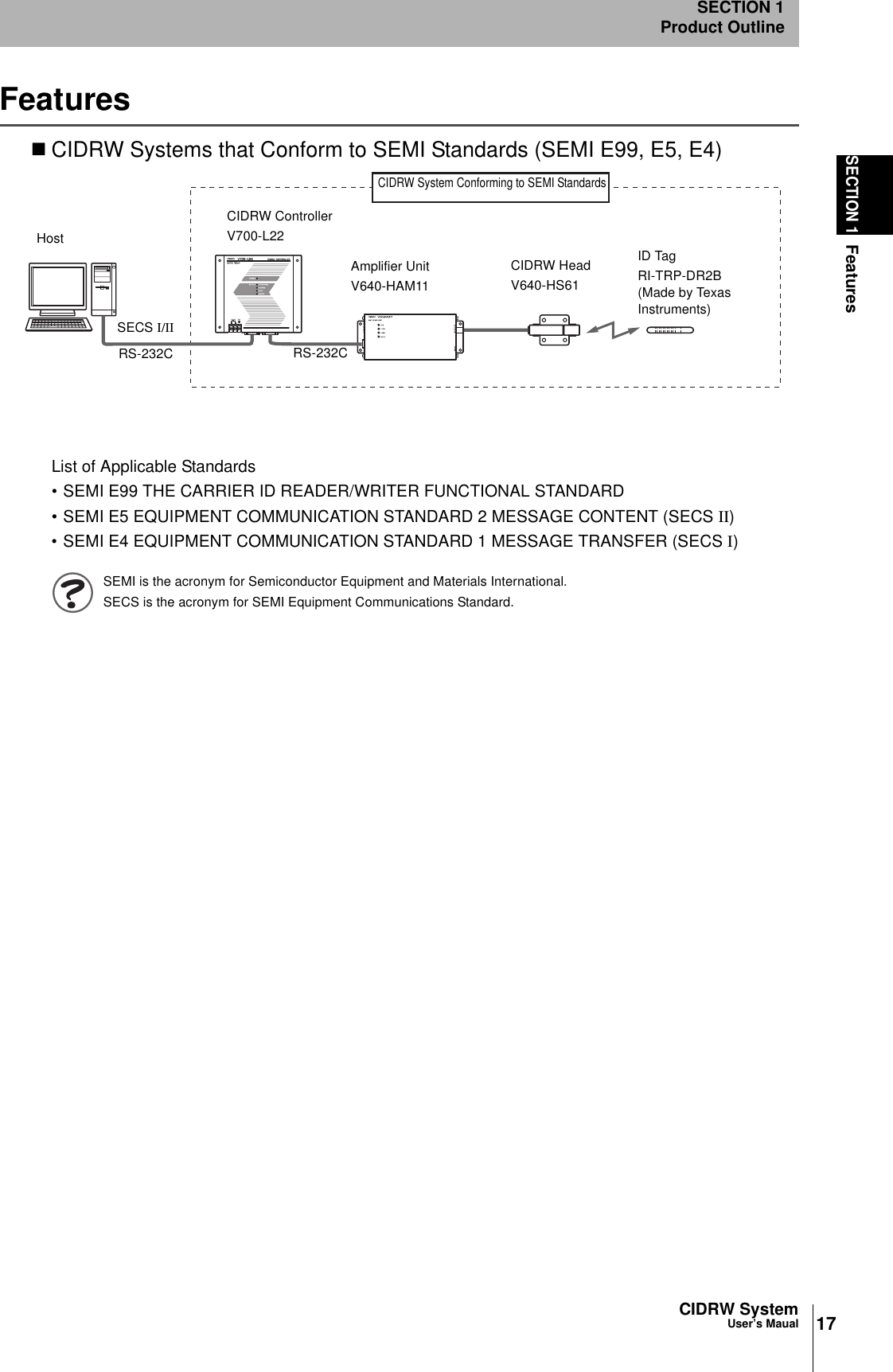
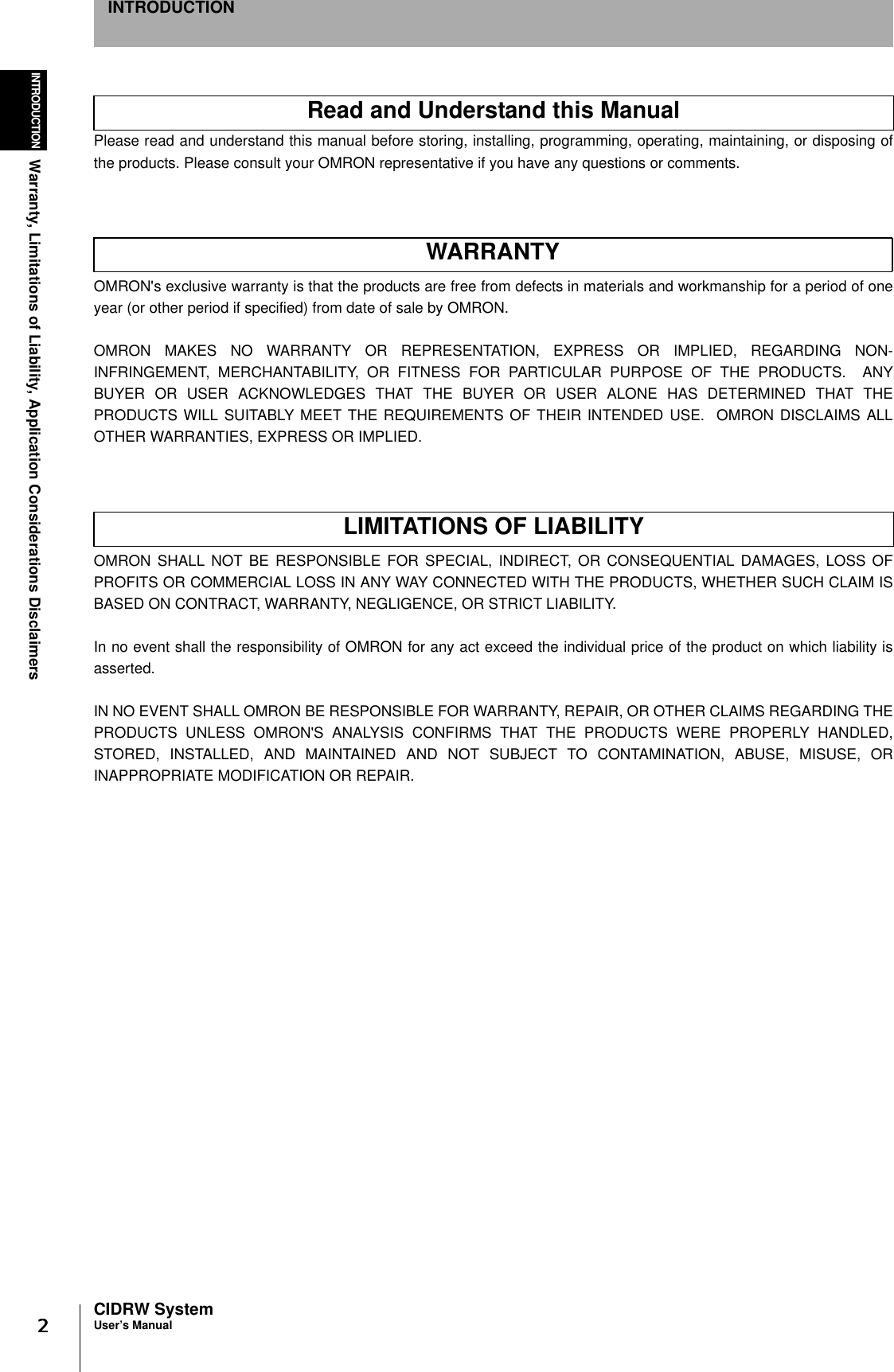
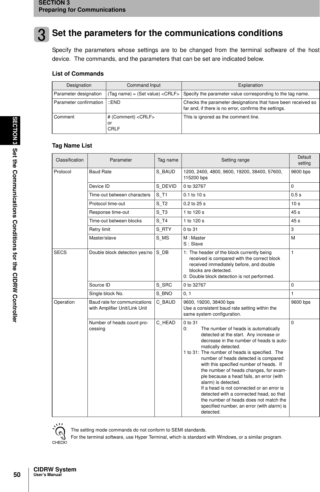
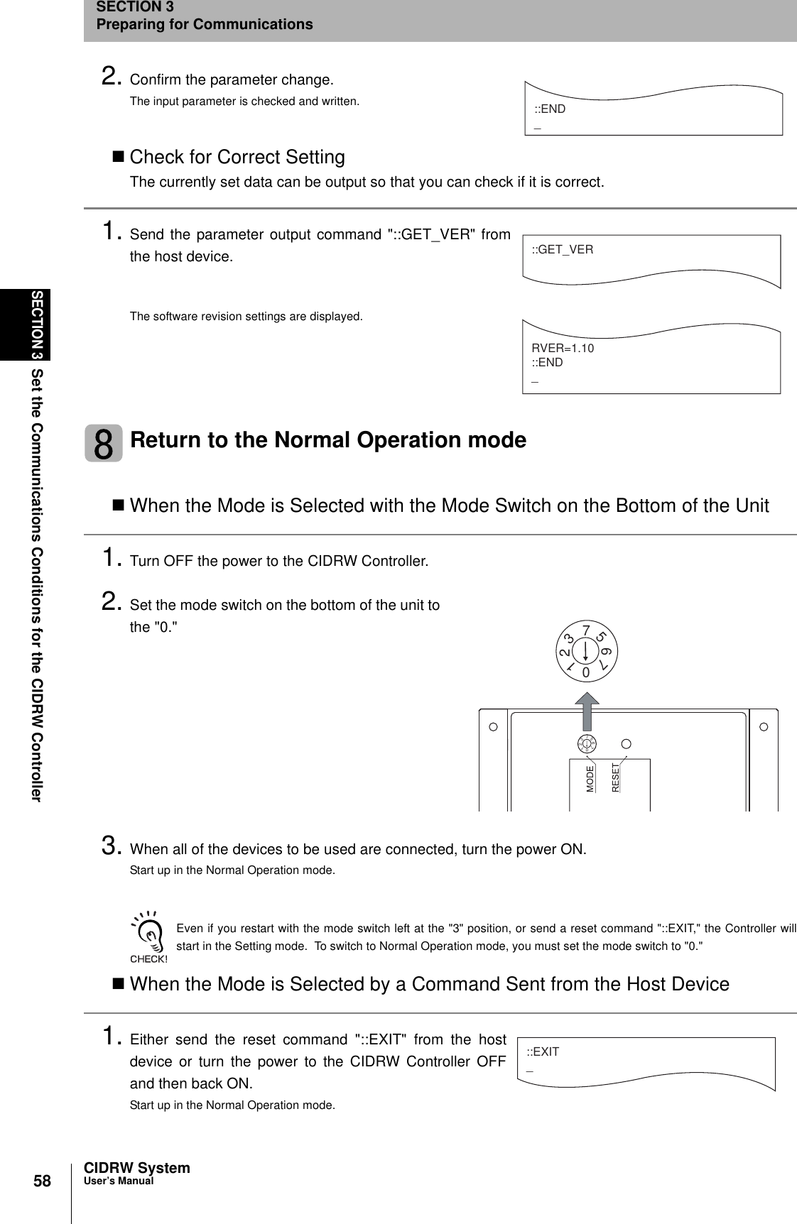
![49CIDRW SystemUser’s ManualSECTION 3Set the Communications Conditions for the CIDRW ControllerSECTION 3Preparing for Communications3. When all of the devices to be used are connected, turn the power ON.The system starts up in the Setting mode, and the indicators react as shown below.Sending a Switching Command from the Host DeviceThis method is convenient when the unit has already been mounted and the switch on the bottom can-not be repositioned to "3."During operation in the Normal Operation mode, a command is sent from the host device to switch tothe Setting mode.1. Send a subsystem command (S18F13 ChangeState CPVAL1 = "PS") from the host device.Refer to page page 77.CPVAL1="PS" is an expansion designation unique to V700-L22 and does not conform to SEMI standards.The system is automatically restarted and the mode switches to the Setting mode.The operation indicators react as shown below.Start the terminal softwareUse the host device's terminal software for the setting.The commands and communications conditions in the setting mode are unique to OMRON. They do not conform to theSEMI standards. For the terminal software, use Hyper Terminal, which is standard with Windows, or a similar program.The communications conditions for communication between the host device and CIDRW Controllerare fixed. Make the following settings using the terminal software.OPERATING ALARMS BUSY ERROROPERATING ALARMS BUSY ERRORItem SettingBaud rate 9600 bpsData length 8 bitsParity EVENStop bit 1Communications control NoneSend code At the end of a line (when [ENTER] is input), the "line feed" characters ([LF]) are appended.Display Local echo](https://usermanual.wiki/Omron/6CYCIDV6400304/User-Guide-486045-Page-48.png)
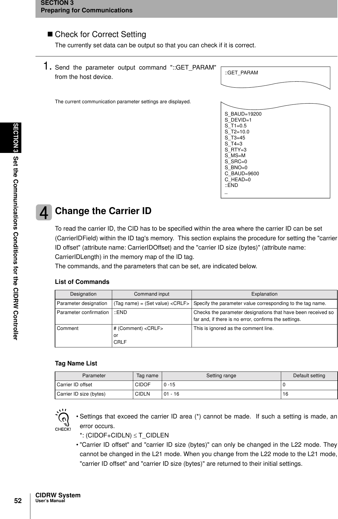
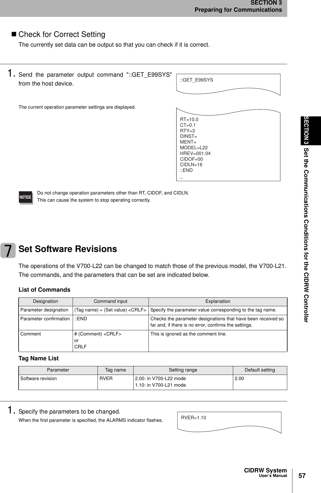
![51CIDRW SystemUser’s ManualSECTION 3Set the Communications Conditions for the CIDRW ControllerSECTION 3Preparing for Communications1. Specify the parameters to be changed.When the first parameter is specified, the ALARMS indicator flashes.2. Confirm the parameter change.The input parameter is checked and written.When writing is completed, a message indicating the result is displayed.The ALARMS indicator lights.If writing is completed with an error, the parameters are not updated.The figure in square brackets [ ] indicates the line number where theerror was first detected. If a parity error is detected in the received char-acters, this figure is [0].Check the sent data based on this information.A text file is created based on the data that is keyed in, as shown below, and this data can be conveniently transmittedusing the terminal's text file send function.S_BAUD=19200S_DEVID=1S_BNO=0_::END _SETUP_COMPLETE_SETUP_FAILED [2]_When writing is completed without errorWhen writing is completed with an error#Parameter Setting File for SystemA#ProtocolS_BAUD=19200S_DEVID=1#SECSS_BNO=0::ENDExample: PRM.TXT](https://usermanual.wiki/Omron/6CYCIDV6400304/User-Guide-486045-Page-50.png)
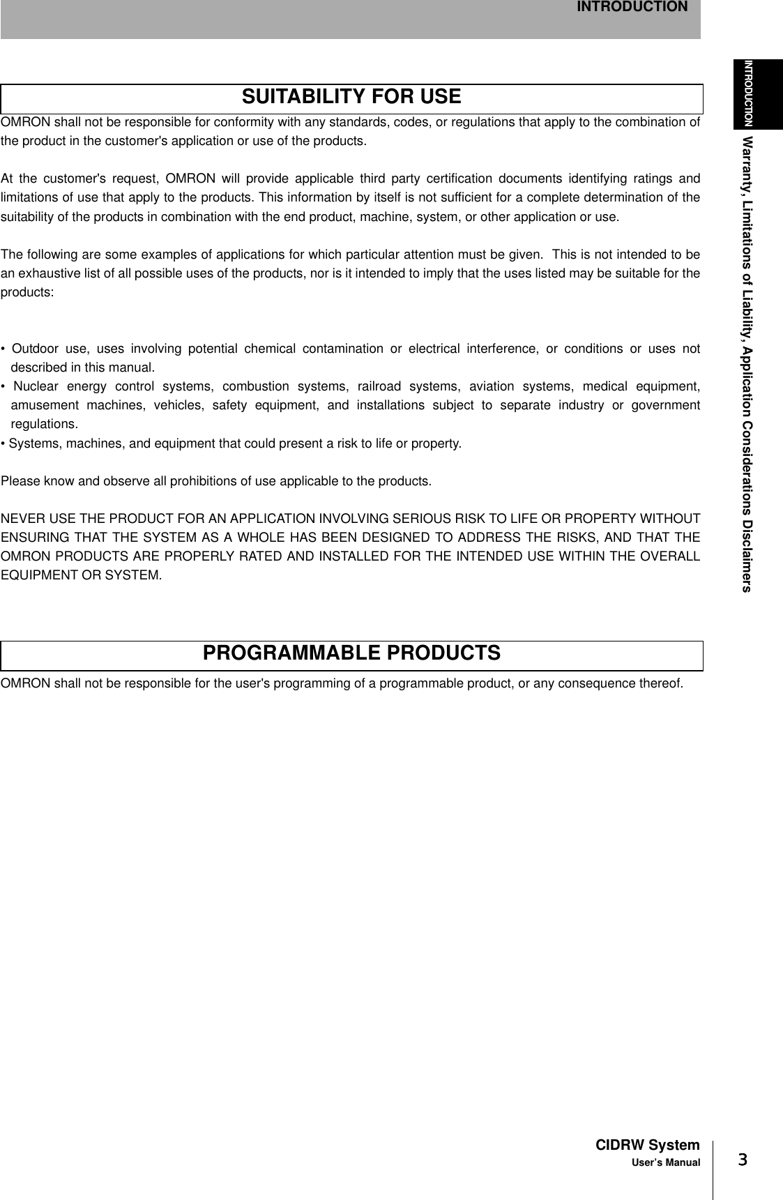
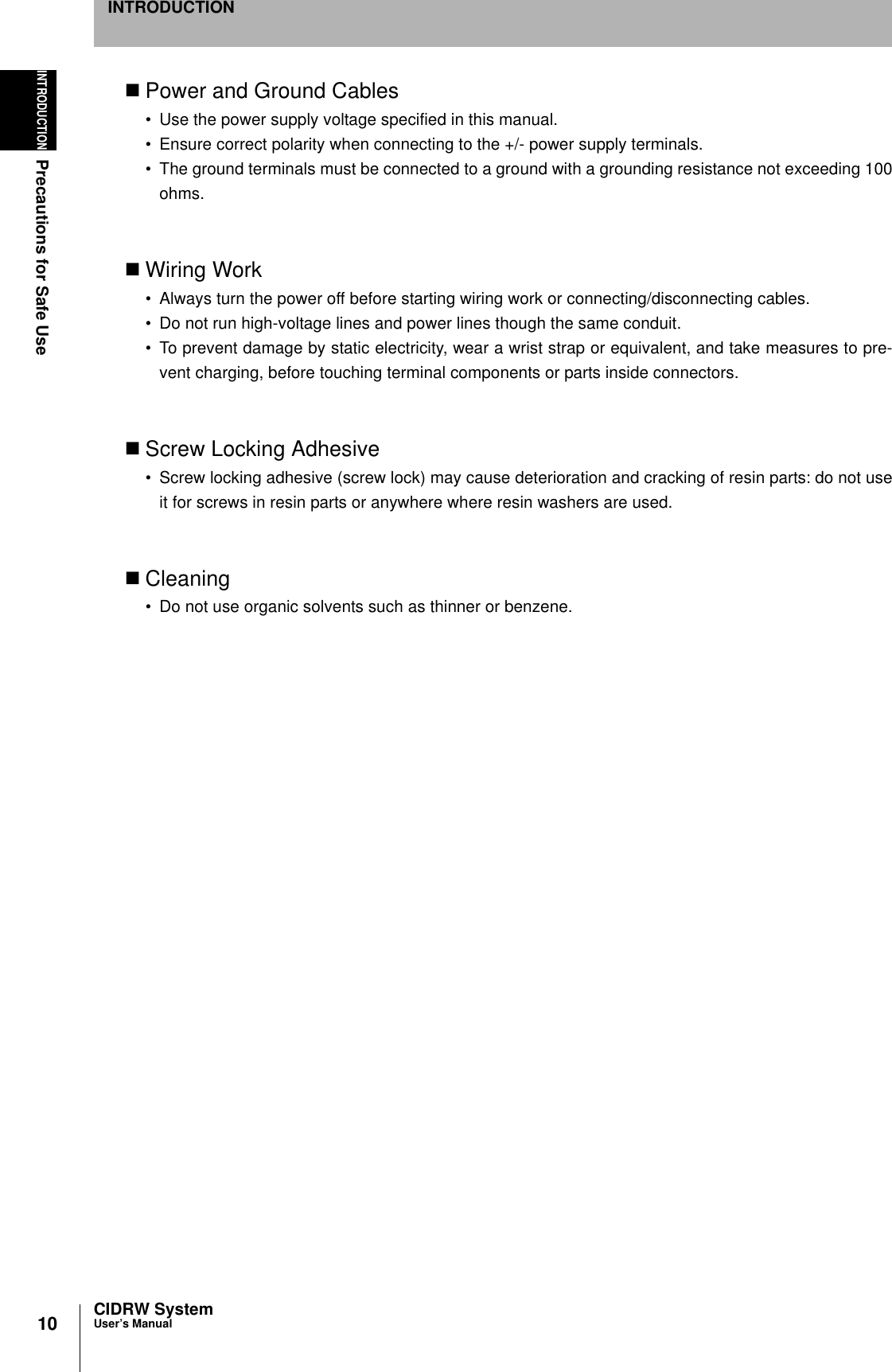
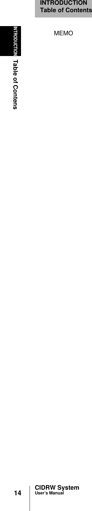
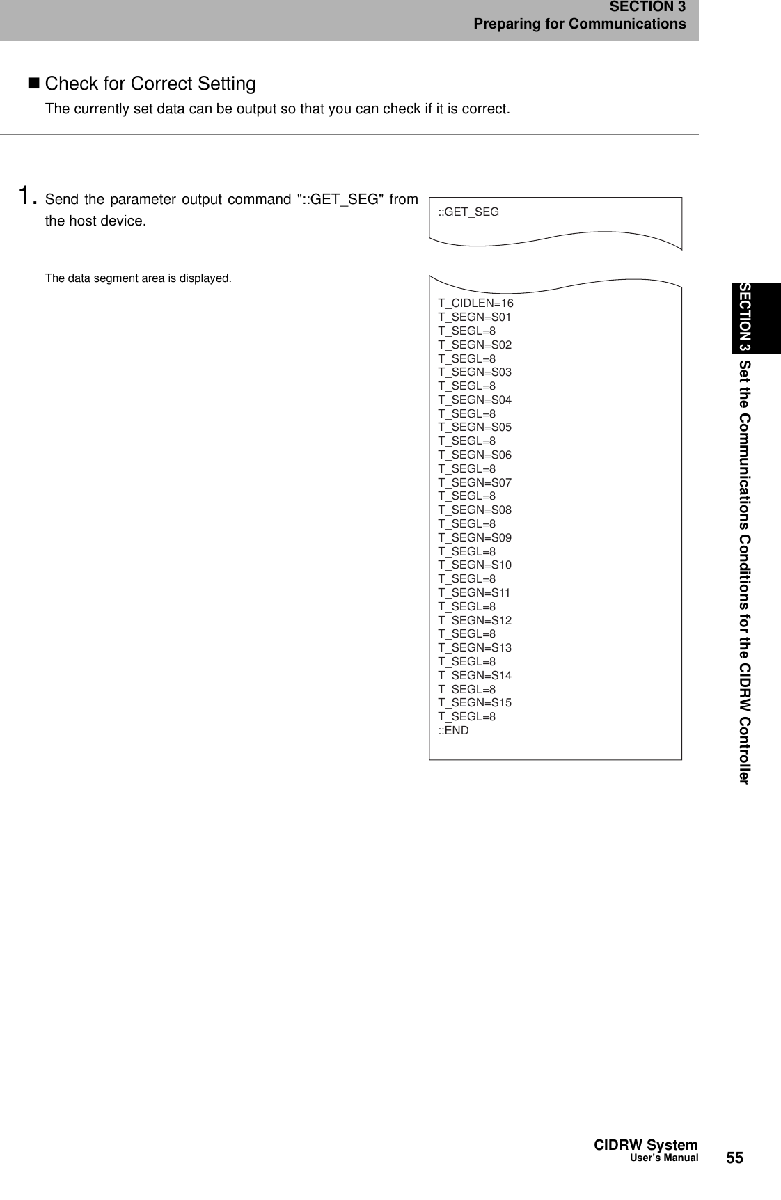
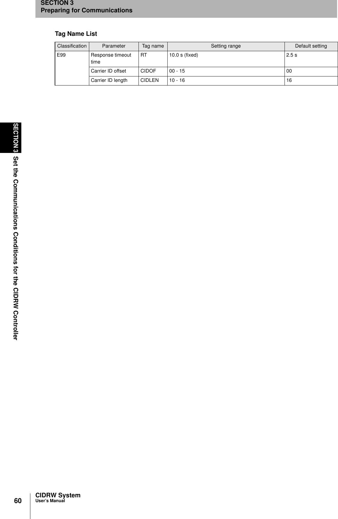
![54SECTION 3Set the Communications Conditions for the CIDRW ControllerCIDRW SystemUser’s ManualSECTION 3Preparing for Communications1. The form of the input from the host device is shown in thefigure to the right.When the first parameter is specified, the ALARMS indicator flashes.2. Confirm the parameter change.The input parameter is checked and written.When writing is completed, a message indicating the result is displayed.The ALARMS indicator lights.If writing is completed with an error, the parameters are not updated.The figure in square brackets [ ] indicates the line number where theerror was first detected. If a parity error is detected in the received char-acters, this figure is [0].Check the sent data based on this information.Tag Name ListParameter Tag name Setting range Default settingNumber of bytes in the carrier ID T_CIDLEN 16 (fixed)The setting must maintain the following relationship(CIDOF + CIDLN) ≤ T_CIDLEN16Segment name T_SEGN "S01" to "S99" "S01" to "S28"Number of bytes in a segment T_SEGL 8 (fixed) 8T_CIDLEN=16T_SEGN=S01T_SEGL=8T_SEGN=S02T_SEGL=8T_SEGN=S03T_SEGL=8T_SEGN=S04T_SEGL=8T_SEGN=S05T_SEGL=8T_SEGN=S06T_SEGL=8T_SEGN=S07T_SEGL=8T_SEGN=S08T_SEGL=8T_SEGN=S09T_SEGL=8T_SEGN=S10T_SEGL=8T_SEGN=S11T_SEGL=8T_SEGN=S12T_SEGL=8T_SEGN=S13T_SEGL=8T_SEGN=S14T_SEGL=8T_SEGN=S15T_SEGL=8_::END _SETUP_COMPLETE_SETUP_FAILED [2]_When writing is completed without errorWhen writing is completed with an error](https://usermanual.wiki/Omron/6CYCIDV6400304/User-Guide-486045-Page-53.png)
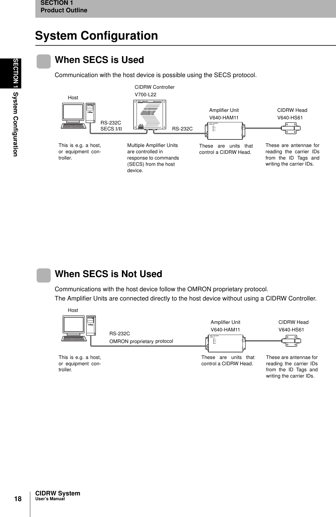
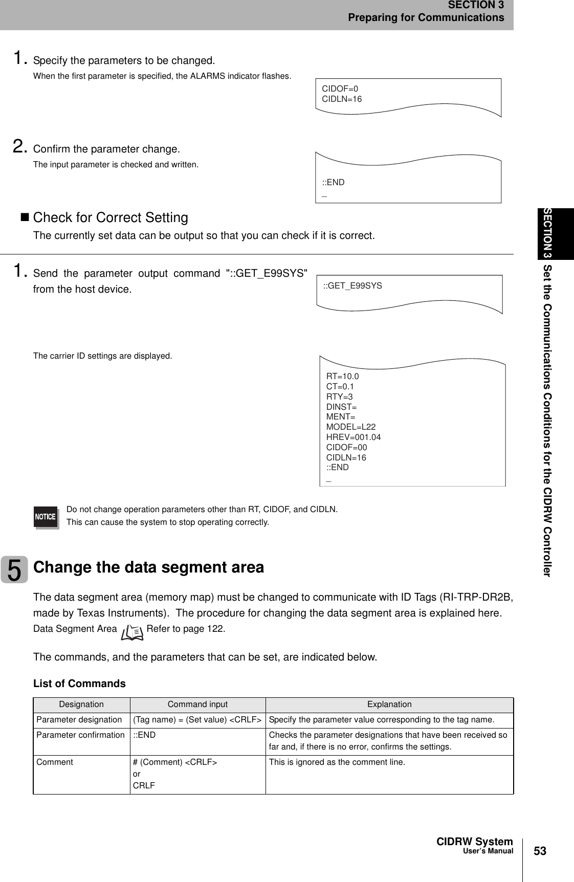
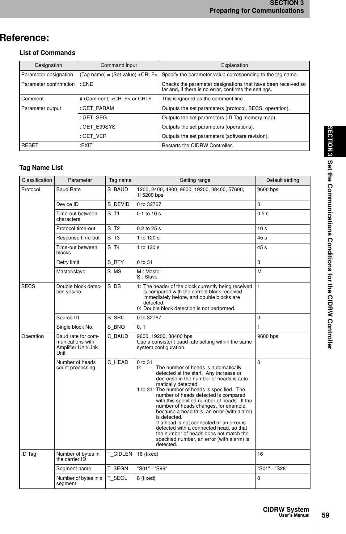
![56SECTION 3Set the Communications Conditions for the CIDRW ControllerCIDRW SystemUser’s ManualSECTION 3Preparing for CommunicationsChange the response time-out timeIn the initial settings of the CIDRW Controller, when ID Tag (RI-TRP-DR2B, made by Texas Instru-ments) data is read or written, a "response time-out" may occur. Be sure to set the response time-outtime to "10 s."The commands, and the parameters that can be set are indicated below.1. Set the response time-out time to "10.0."2. Confirm the parameter change.The input parameter is checked and written.When writing is completed, a message indicating the result is displayed.The ALARMS indicator lights.If writing is completed with an error, the parameters are not updated.The figure in square brackets [ ] indicates the line number where theerror was first detected. If a parity error is detected in the received char-acters, this figure is [0].Check the sent data based on this information.List of CommandsDesignation Command input ExplanationParameter designation (Tag name) = (Set value) <CRLF> Specify the parameter value corresponding to the tag name.Parameter confirmation ::END Checks the parameter designations that have been received so far and, if there is no error, confirms the settings.Comment # (Comment) <CRLF> or CRLFThis is ignored as the comment line.Tag Name ListParameter Tag name Setting range Default settingResponse time-out time RT 10.0 (fixed) 2.5RT=10.0_::END _SETUP_COMPLETE_SETUP_FAILED [2]_When writing is completed without errorWhen writing is completed with an error](https://usermanual.wiki/Omron/6CYCIDV6400304/User-Guide-486045-Page-55.png)
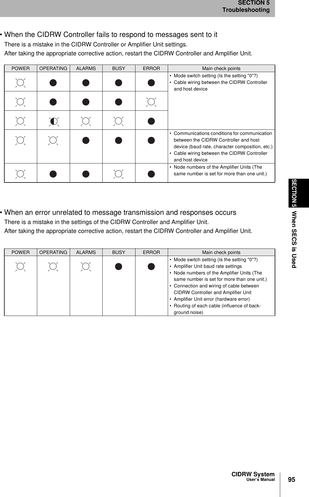
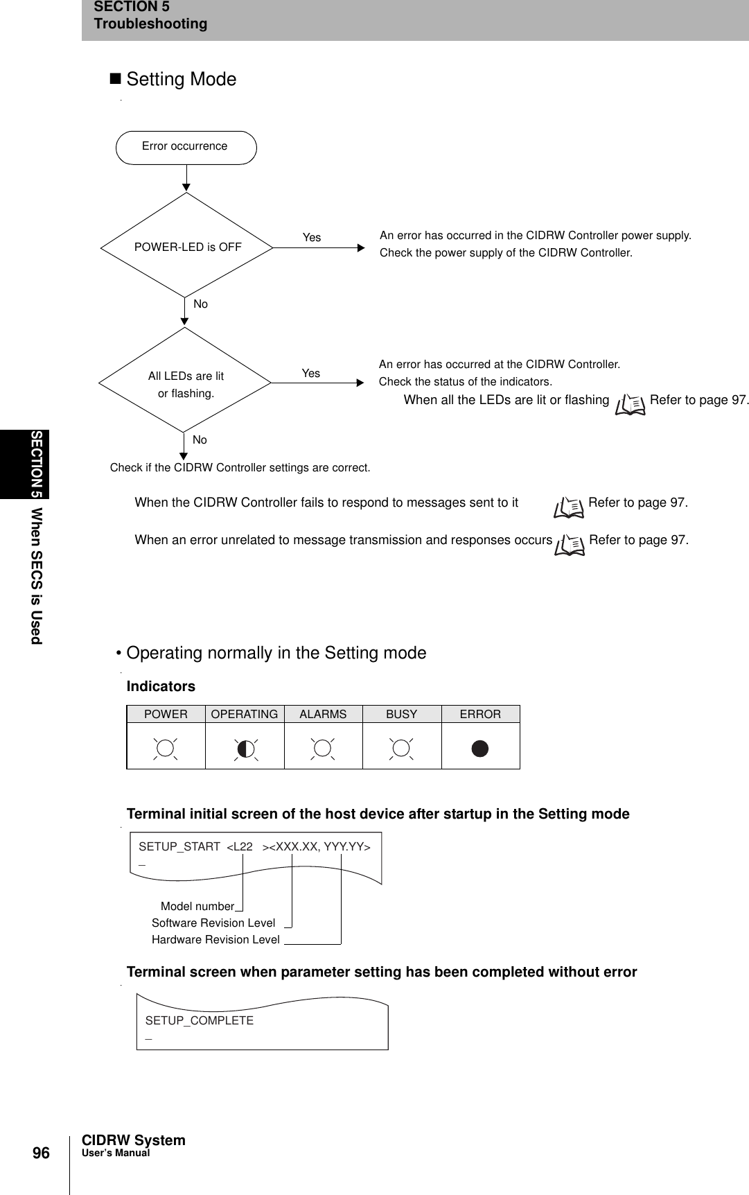
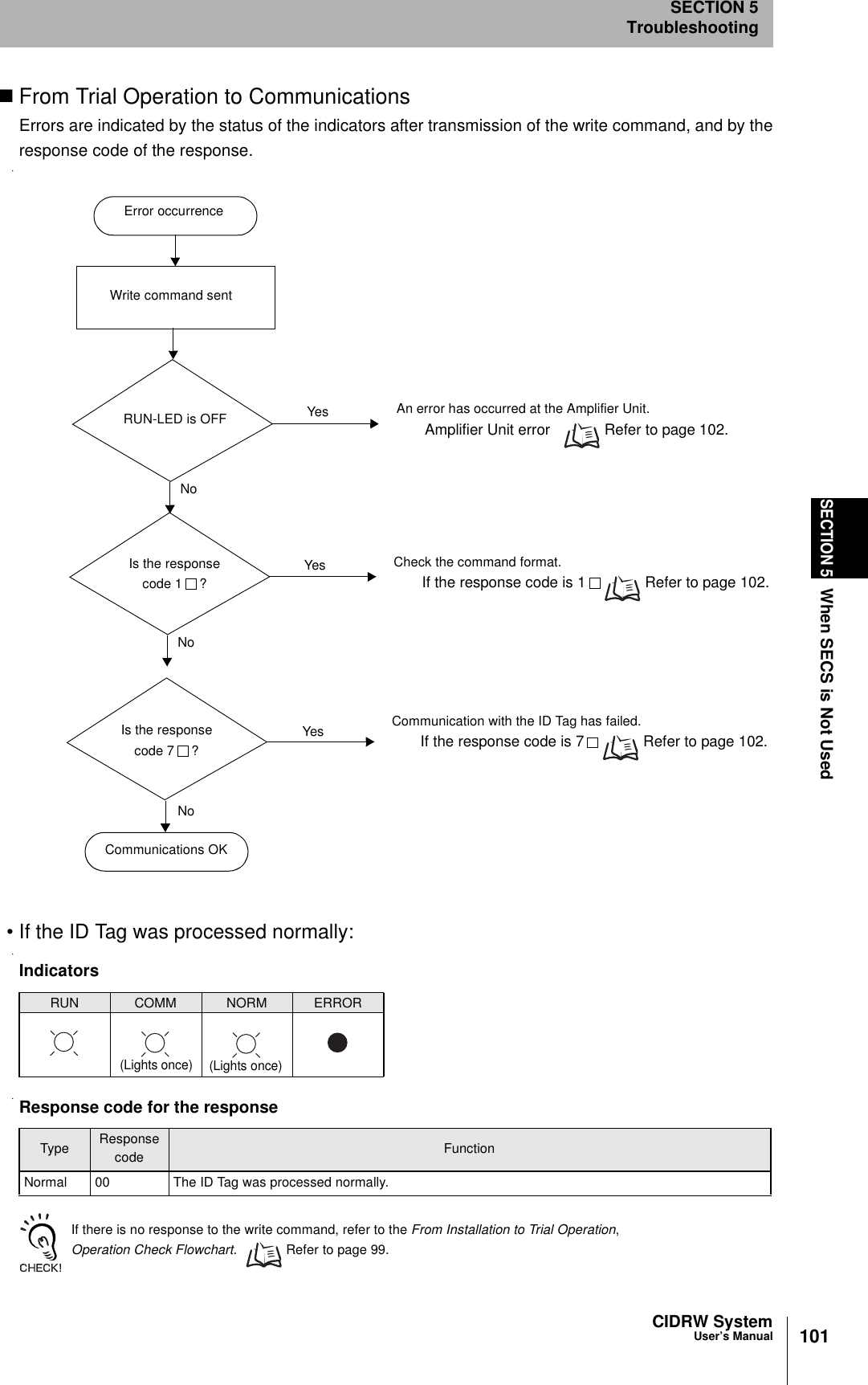
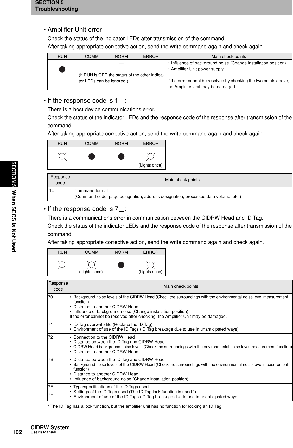
![97CIDRW SystemUser’s ManualSECTION 5When SECS is UsedSECTION 5Troubleshooting• When all the LEDs are lit or flashingAn error has occurred in the CIDRW Controller. After taking appropriate corrective action, restart theCIDRW Controller and check the indicators.• When the CIDRW Controller responds to a message transmissionThere is a mistake in the CIDRW Controller settings or the sent parameters. After taking appropriatecorrective action, restart the CIDRW Controller and check the indicators.• When the CIDRW Controller fails to respond to messages sent to itThere is a mistake in the CIDRW Controller settings or the sent parameters. After taking appropriatecorrective action, restart the CIDRW Controller and check the indicators.• When an error unrelated to message transmission and responses occursThere is a mistake in the settings of the CIDRW Controller or Amplifier Unit. After taking appropriatecorrective action, restart the CIDRW Controller and Amplifier Unit and check the indicators.POWER OPERATING ALARMS BUSY ERROR Main check points• Supply of 24 VDC power• The CIDRW Controller may be damaged.• Mode switch setting (Is the setting "3"?)If the error cannot be resolved after checking, the CIDRW Controller may be damaged.• The CIDRW Controller may be damaged.POWER OPERATING ALARMS BUSY ERROR Main check points• Sent parameters (Are the parameters cor-rect? Are the settings correct?)Response ContentsSETUP_FAILED [ ] The parameters are not updated. The figure in square brackets [ ] indicates the line number where the error was first detected. If a parity error is detected in the received characters, this figure is [0].POWER OPERATING ALARMS BUSY ERROR Main check points• Transmission parameters (Are the parameters correct?)• Communications conditions for communication between the CIDRW Controller and the host device (baud rate, character composition, etc.)• Mode switch setting (Is the setting "3"?)POWER OPERATING ALARMS BUSY ERROR Main check points• Mode switch setting (Is the setting "3"?)](https://usermanual.wiki/Omron/6CYCIDV6400304/User-Guide-486045-Page-96.png)
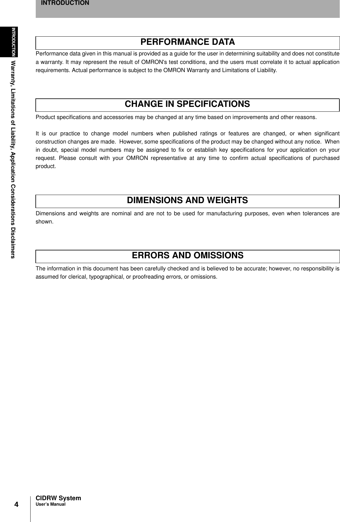
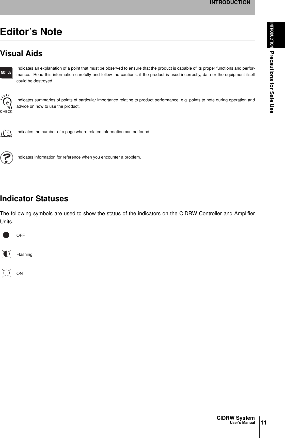
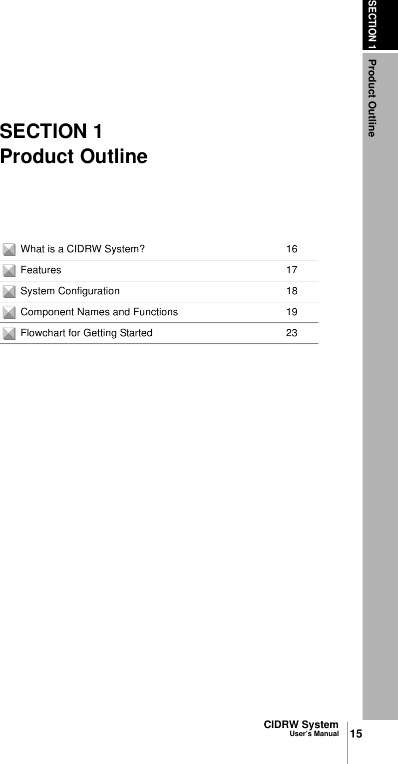
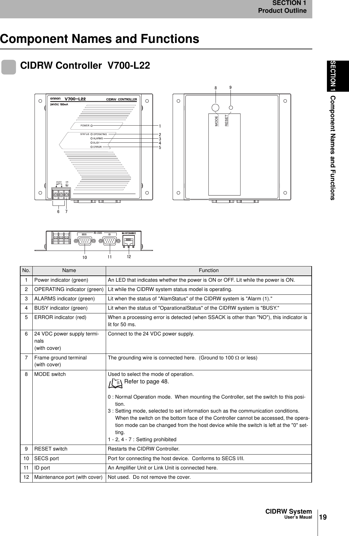
![CIDRW SystemUser’s ManualSECTION 6ASCII Code TableSECTION 6Appendix129ASCII Code TableLeftmostbitsRight-most bitsb8 - b50000 1001 0010 0011 0100 0101 0110 0111 1000 1101 1010 1011 1100 1101 1110 1111b4 - b1RowLine0 12345678910 11 12 13 14 150000 0NUL TC7(DLE)(SP) 0 @ P ` pUndefined Undefined Undefined0001 1TC1(SOH) DC1!1AQaq0010 2TC2(STX) DC2"2BRbr0011 3TC3(ETX) DC3#3CScs0100 4TC4(EOT) DC4$4DTdt0101 5TC5(NEQ) TC8(NAK)%5EUeu0110 6TC6(ACK) TC9(SYN)&6FVf v0111 7BEL TC10(ETB)'7GWgw1000 5FE0(BS) CAN(8HXhx1001 9FE1(HT) EM)9IYiy1010 10FE2(LF) SUB*:JZjz1011 11FE3(VT) ESC+;K[k{1100 12FE4(FF) IS4(FS),<L\ l |1101 13FE5(CR) IS3(GS)-=M]m}1110 14S0 IS2(RS).>N^nÅP1111 15S1 IS1(US)/?O_oDEL](https://usermanual.wiki/Omron/6CYCIDV6400304/User-Guide-486045-Page-117.png)