Omron 6CYCIDV6700104 Modular RFID Transmitter User Manual v670cf01
Omron Corporation Modular RFID Transmitter v670cf01
UserManual.wiki
>
Omron
>
6CYCIDV6700104 User Manual
User Manual
Navigation menu
Upload a User Manual
Namespaces
Wiki Guide
HTML
PDF
Info
Views
User Manual
Discussion / Help
Navigation
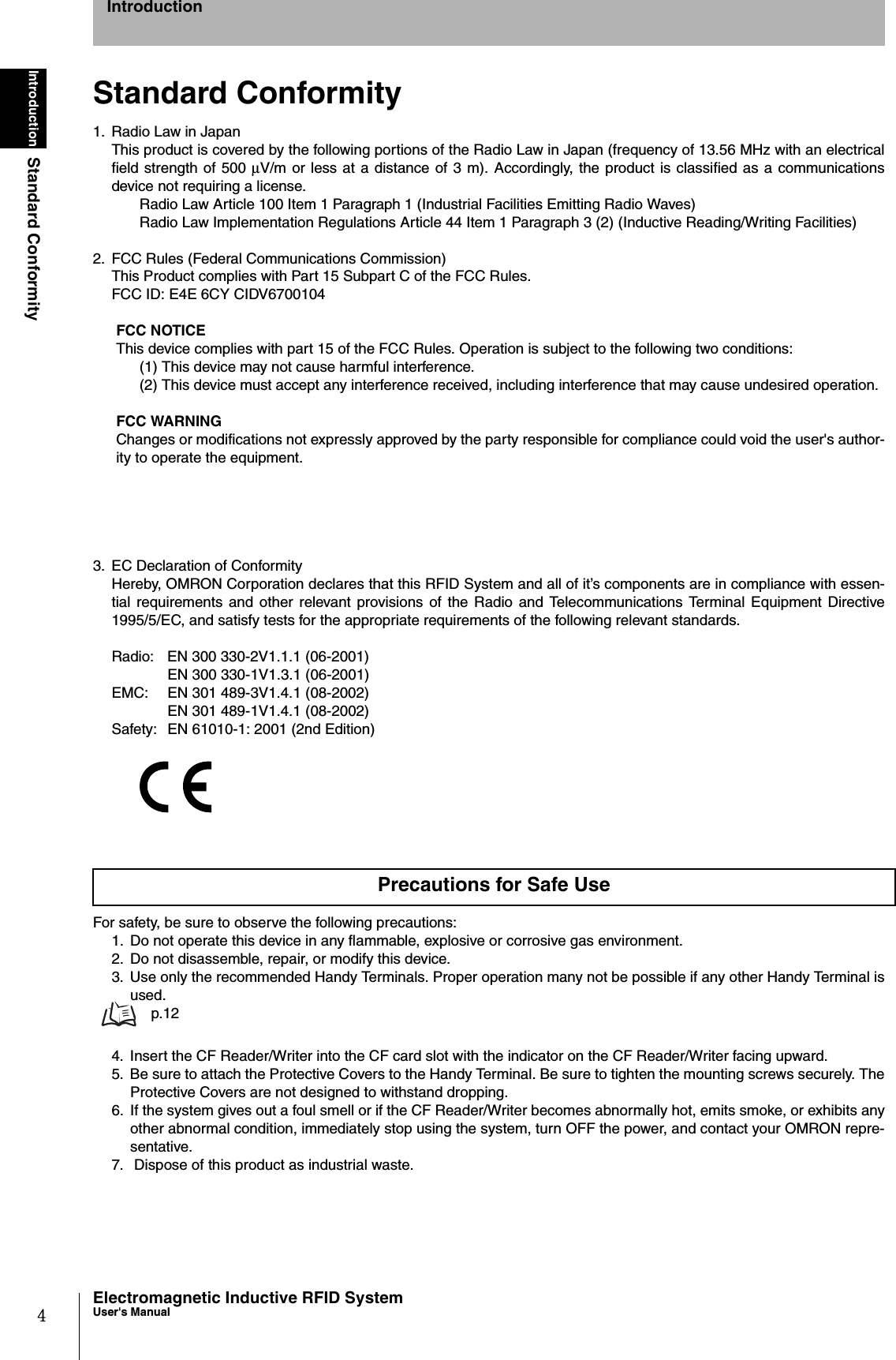
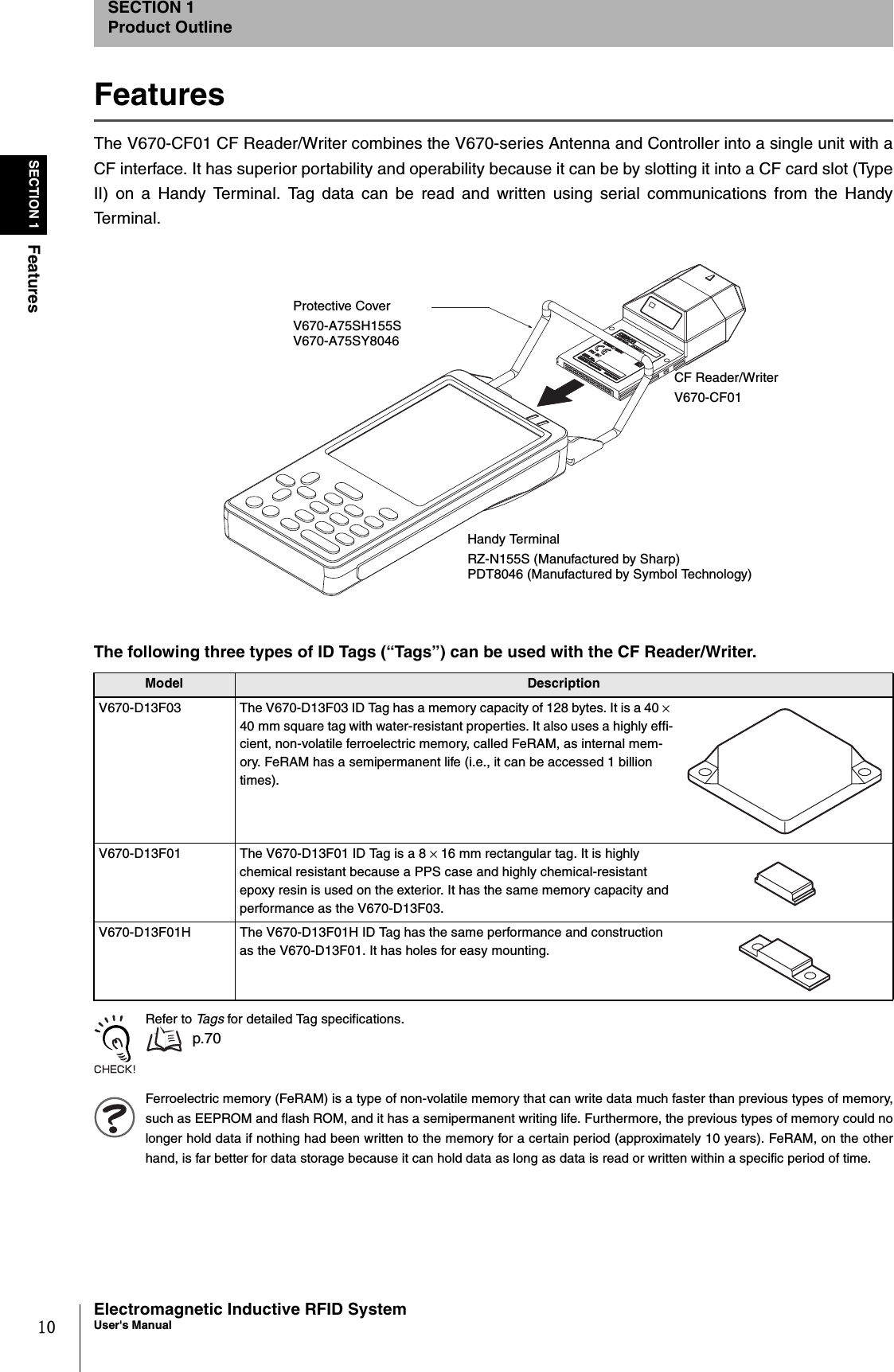
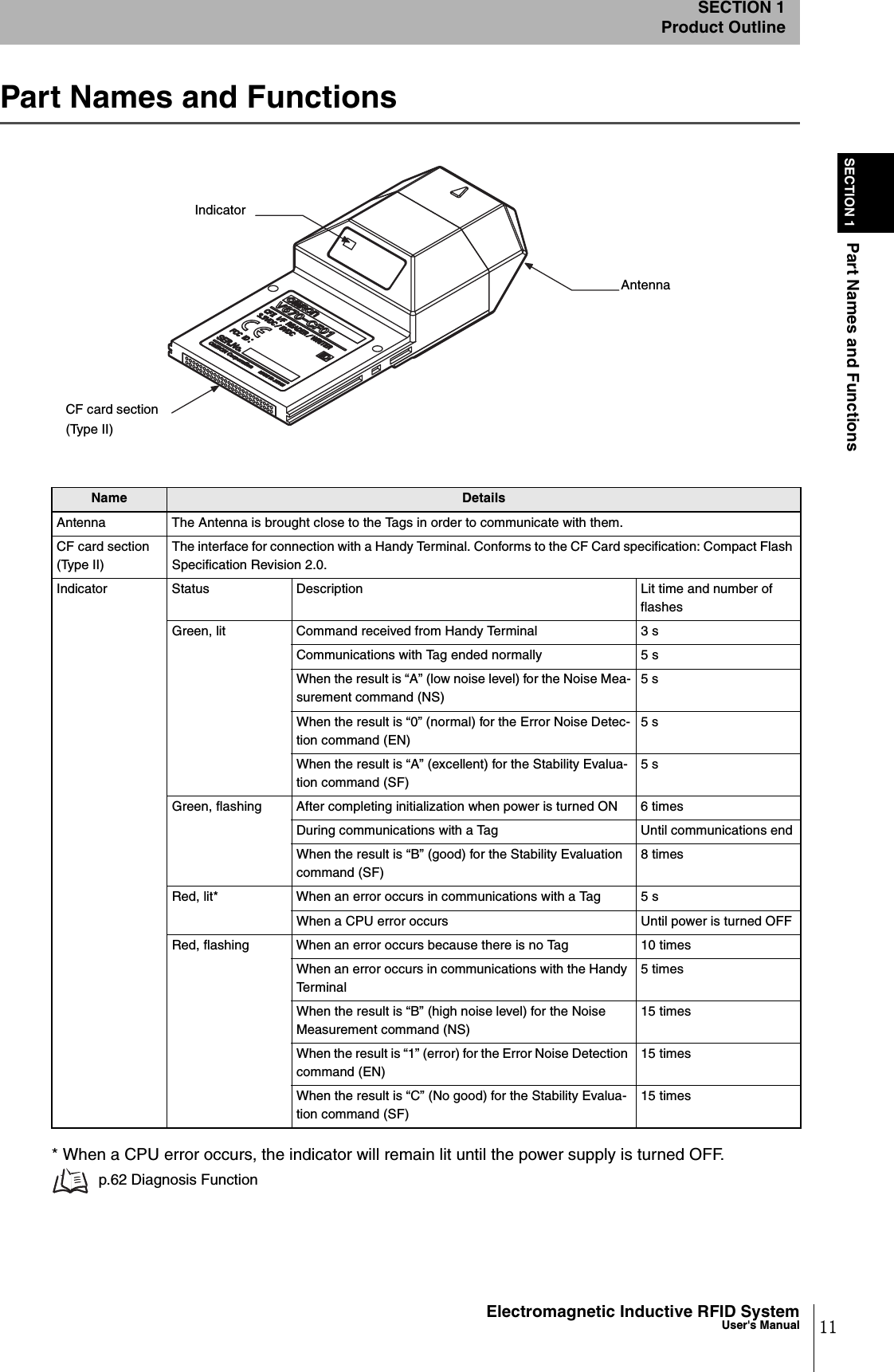
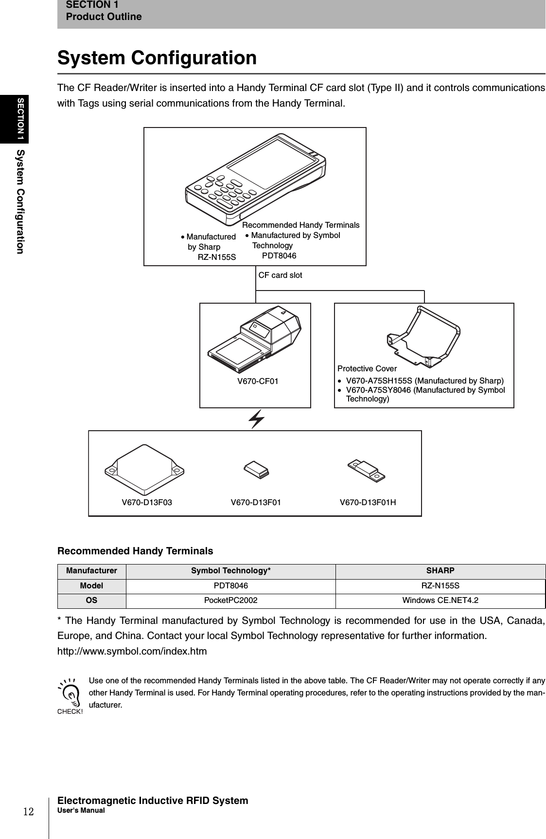
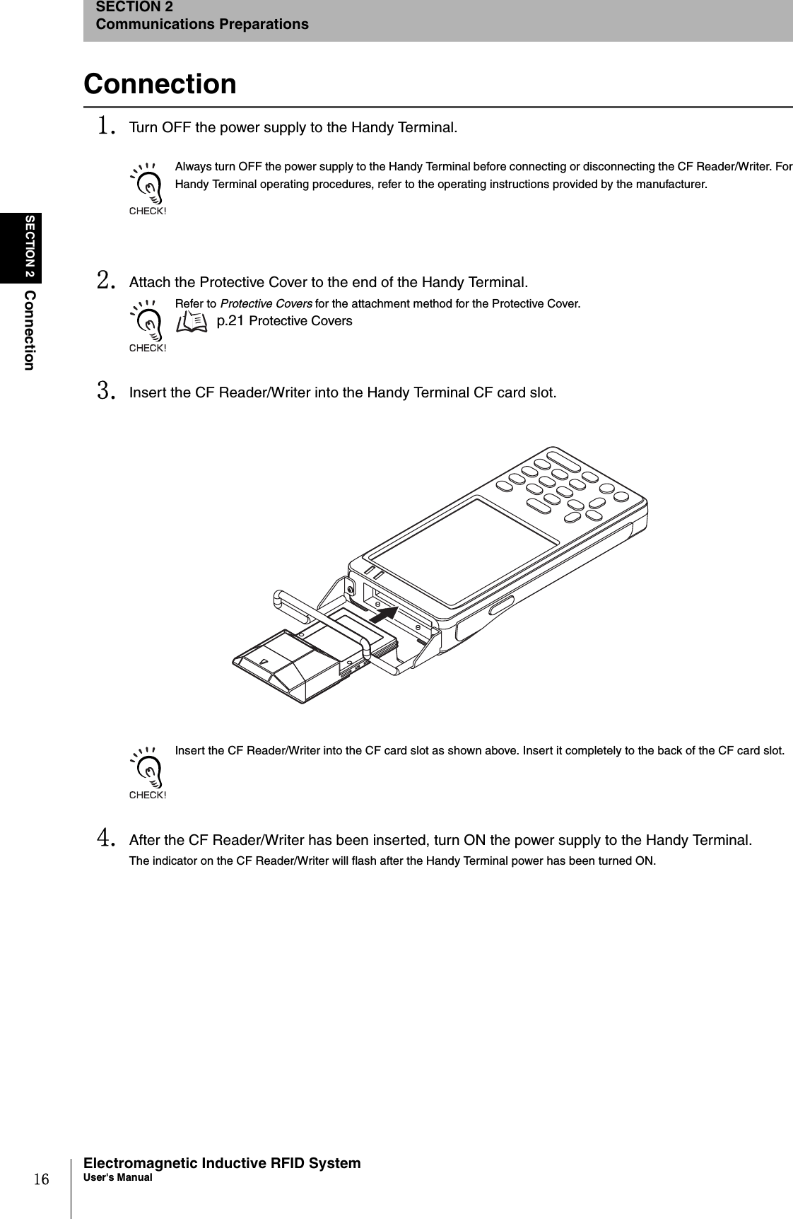
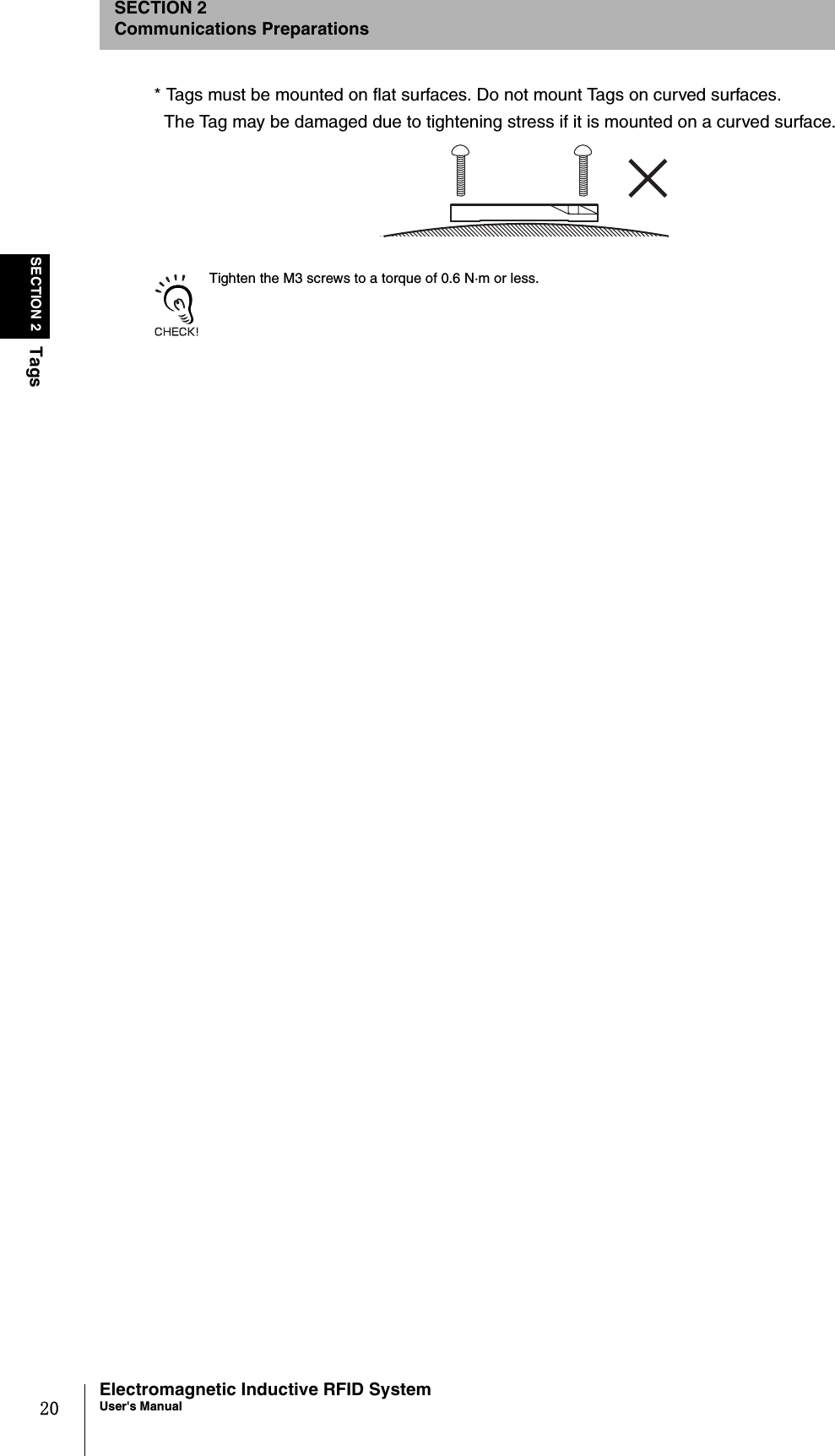
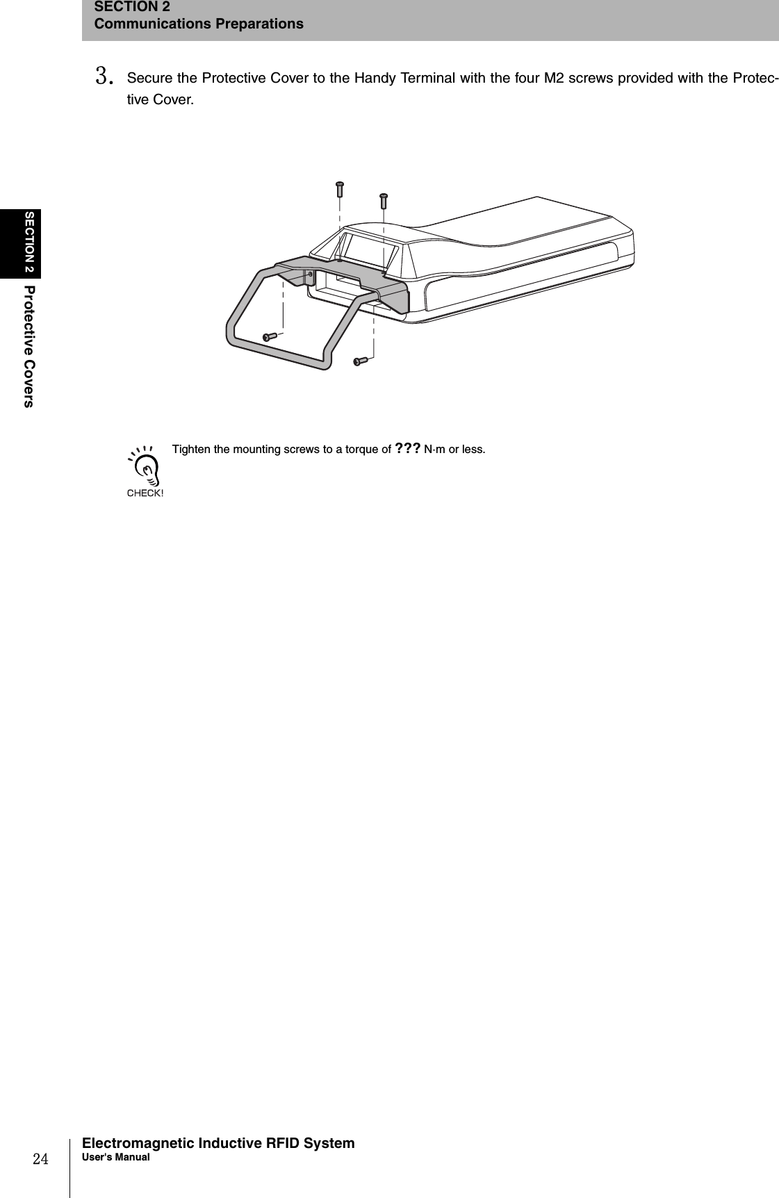
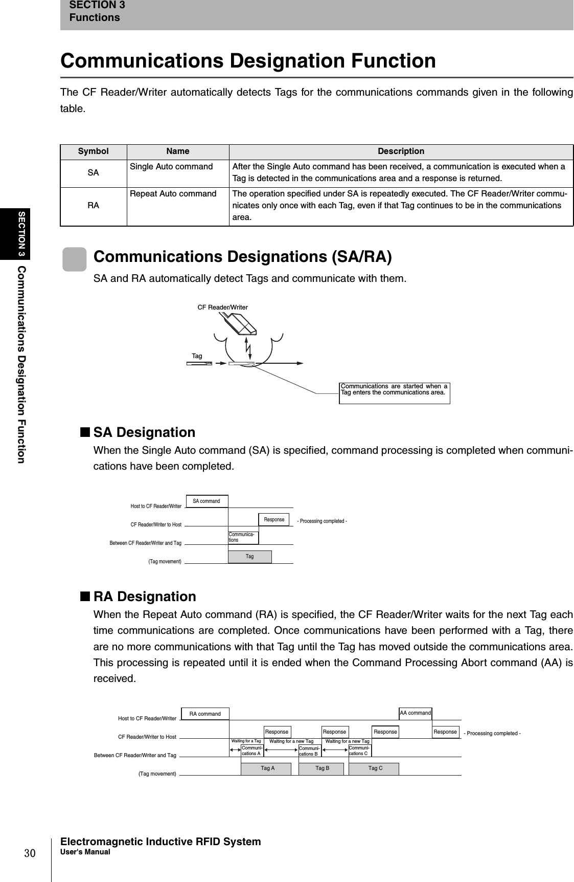
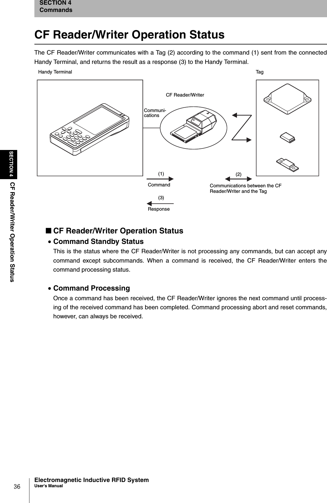
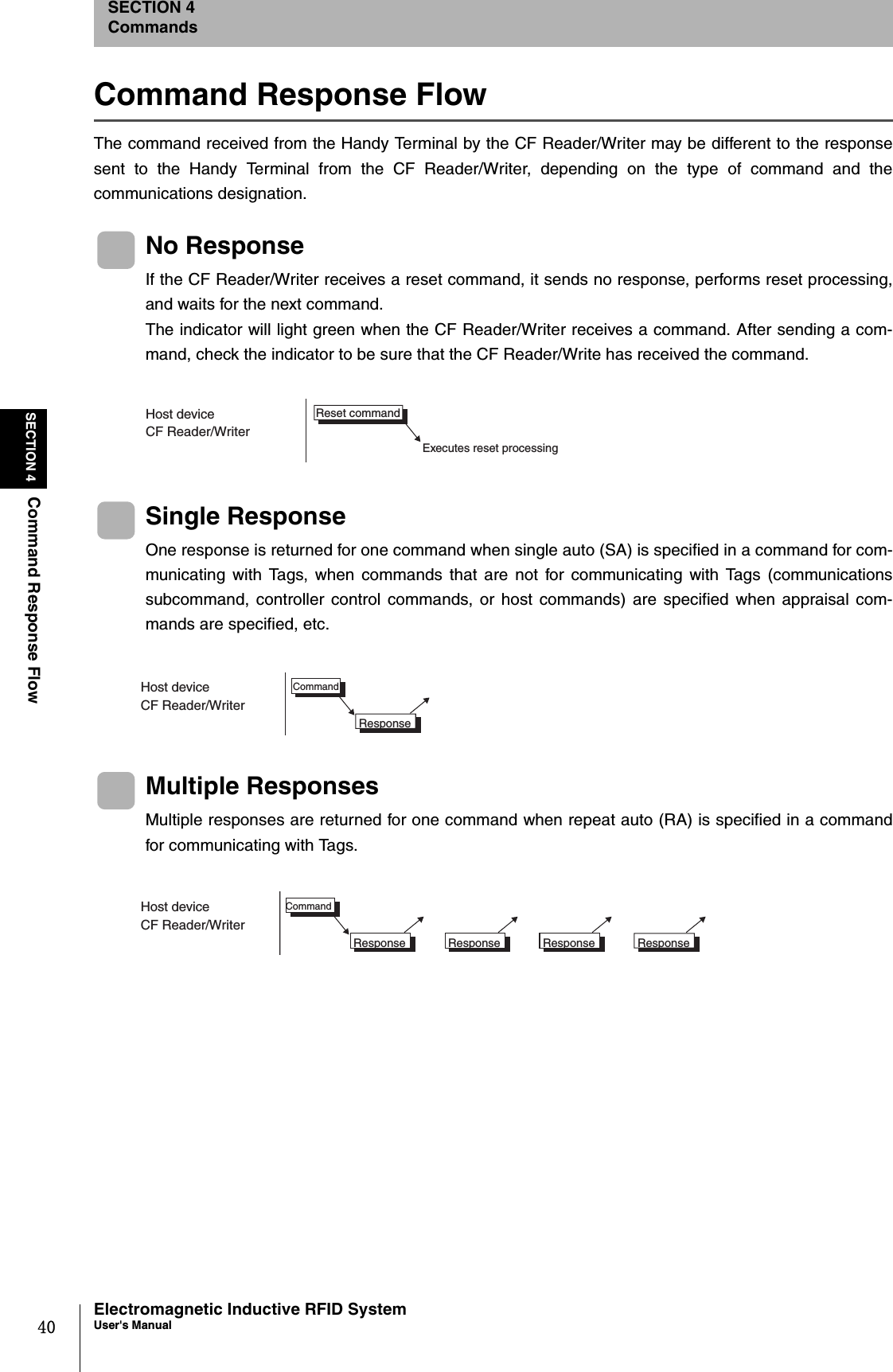
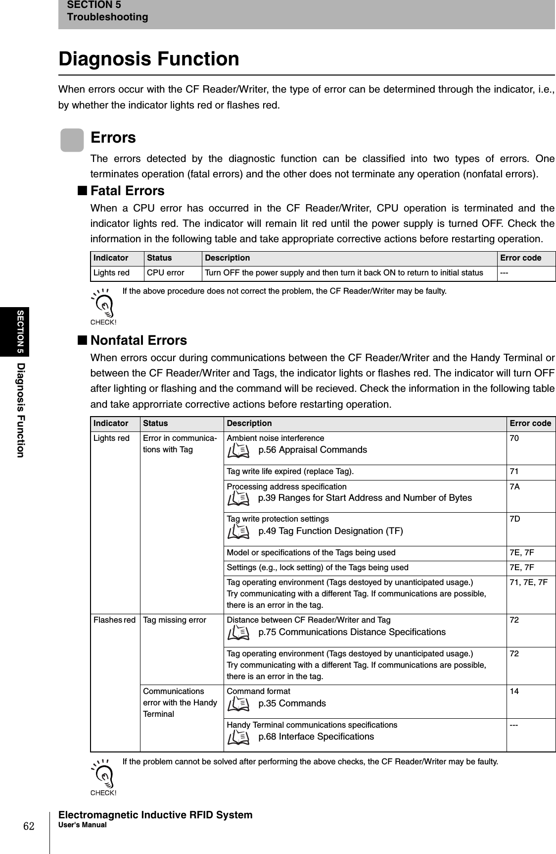
![44SECTION 4Communications CommandsElectromagnetic Inductive RFID SystemUser's ManualSECTION 4CommandsCommunications CommandsThis section describes the commands used for communicating with Tags.Read (RD)Reads data from the area specified by start address and number of bytes.Example: Reading 8 Bytes of Data Starting from Address 0000h (Single Auto, Hexadecimal) Send data: RDSAH1000008*[CR] Receive data: RD00001234567812345678*[CR]Specify the total number of read bytes so that the sum of the read area start address and the number of bytes does notexceed the Tag memory capacity (128 bytes).Example: The number of bytes can be specified between 01h and 70h for a start address of 0010h.Communications designationSpecifies the method for communicating with a Tag.Refer to Communications Designations for details. p.43Data designation Specifies the data format when sending the read data response.“A”: ASCII “H”: Hexadecimal Antenna designation Always “1”.Read area start address Specifies the start address in the Tag memory area for reading data in four hexadecimal digits.Specification range: 0000h to 007FhNo. of read bytes Specifies the number of bytes of data to be read from the Tag in two hexadecimal digits.The maximum number of characters that can be read at one time is 256.Specification range: 01h to 80hRead data Data read from the Tag.The number of characters is the number of read bytes in ASCII, and the number of read bytes times 2 in hexadecimal.2 22211 4㧖CRCommand code "RD" Data desig-na-tion Antenna designa-tion Read area start address No. of read bytes Communica-tions desig-nation Command 2211 2㧖CRCommand code "RD" Retry flag Status flag End code "00" Specified number of bytes Read data Response](https://usermanual.wiki/Omron/6CYCIDV6700104/User-Guide-455260-Page-46.png)
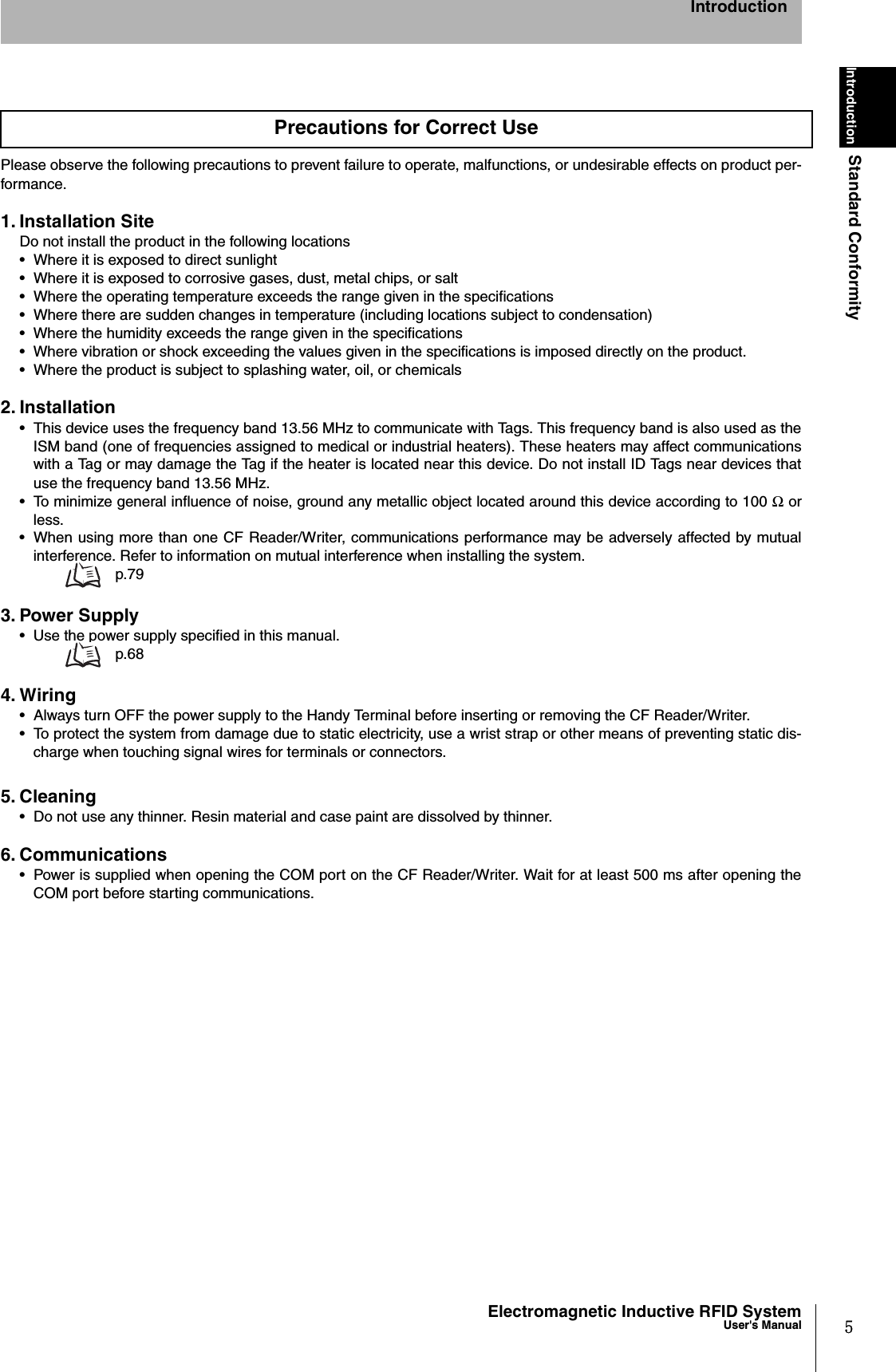
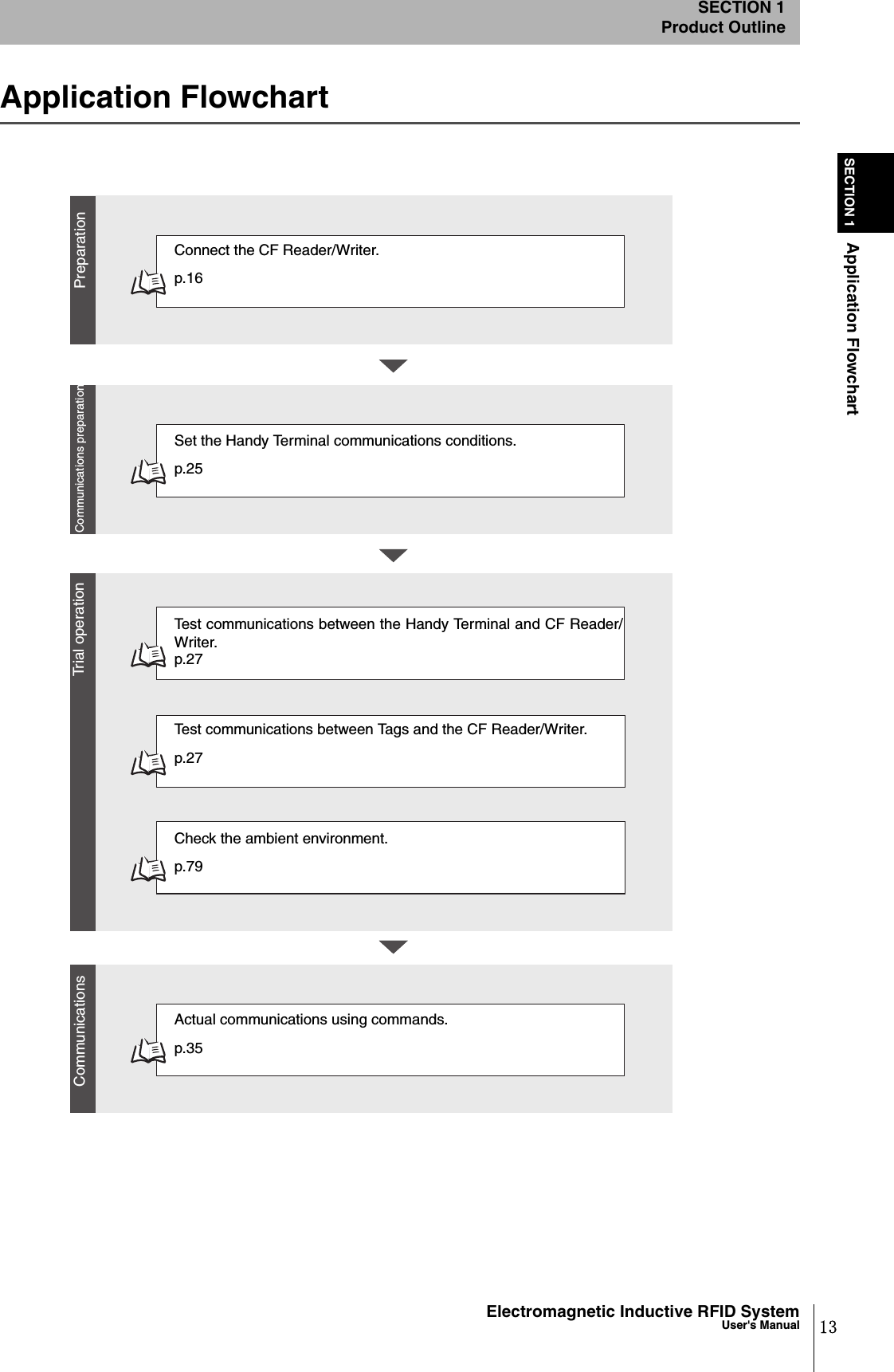
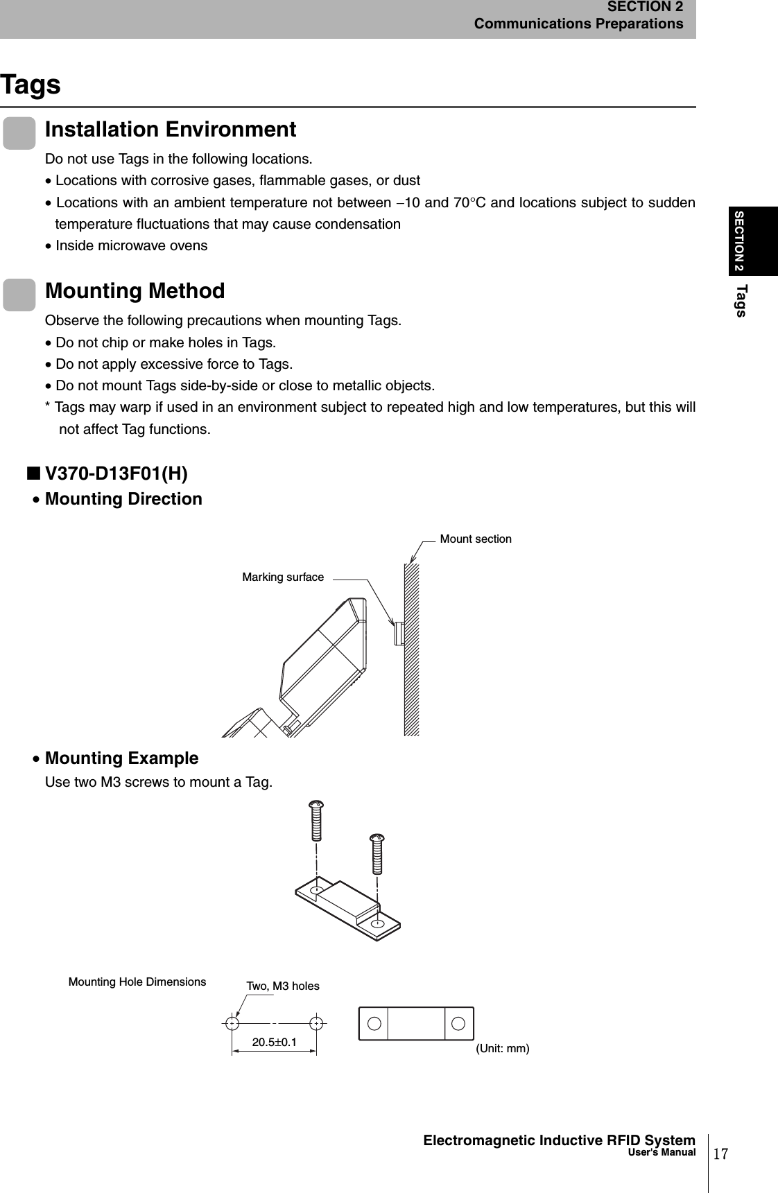
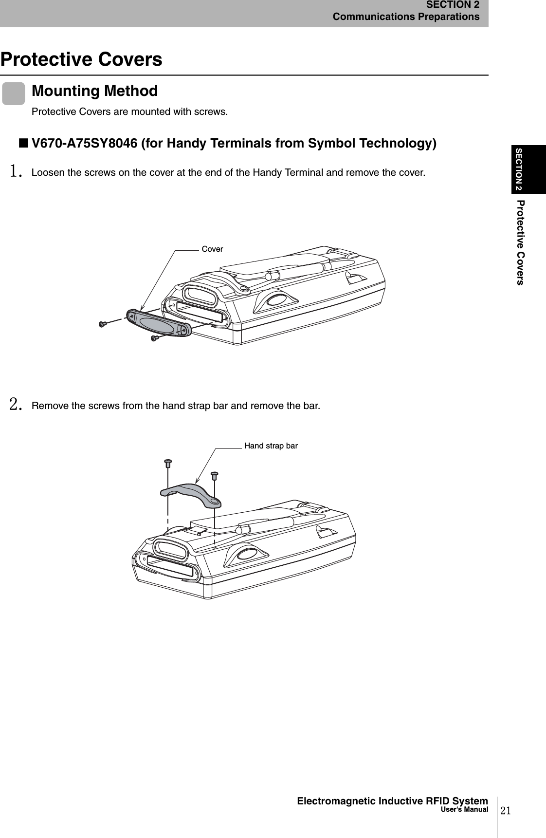
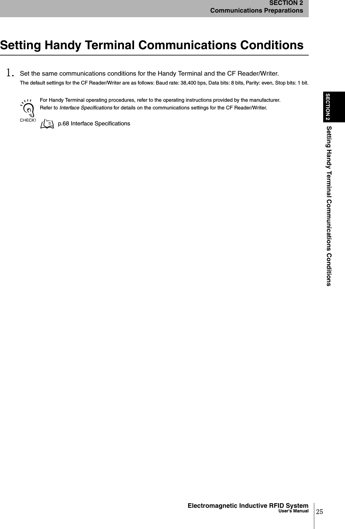
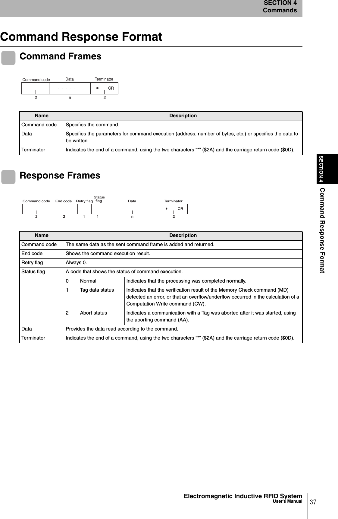
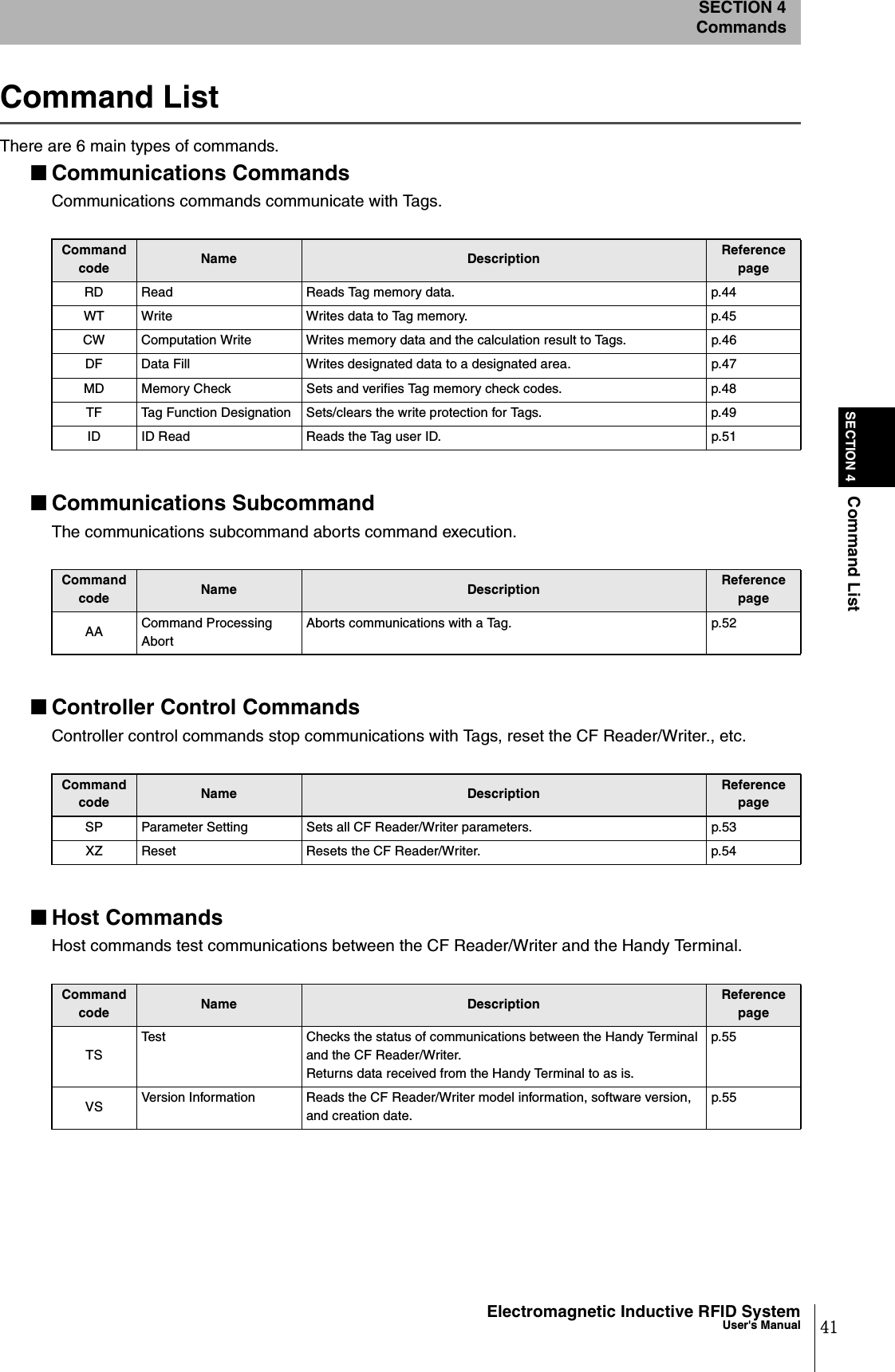
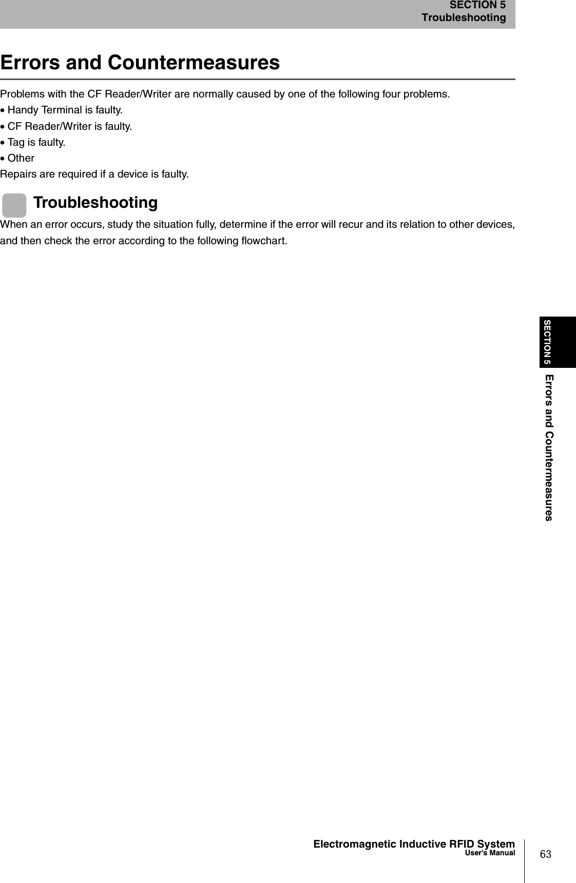
![45Electromagnetic Inductive RFID SystemUser's ManualSECTION 4Communications CommandsSECTION 4CommandsWrite (WT)Writes the specified number of bytes of data starting from the specified start address to a Tag.Example: Writing 4 Bytes of Data (“11223344”) from Address 0010h (Single Auto, Hexadecimal) Send data: WTSAH100100411223344*[CR] Receive data: WT0000*[CR]Specify the total number of write bytes so that the sum of the write area start address and the number of bytes does notexceed the Tag memory capacity (128 bytes).Example: The number of bytes can be specified between 01h and 70h for a start address of 0010h.Communications designationSpecifies the method for communicating with a Tag.Refer to Communications Designations for details. p.43Data designation Specifies the data format when sending write data to Tags.“A”: ASCII“H”: HexadecimalAntenna designation Always “1”.Write area start address Specifies the start address in the Tag memory area for writing data in four hexadecimal digits.Specification range: 0000h to 007FhNo. of write bytes Specifies the number of bytes of data to be written to the Tag in two hexadecimal digits.Specification range: 01h to 80hWrite data Data written to Tags.There will be 2 characters per byte if hexadecimal is specified.2 2 211 4 2㧖CRCommand code "WT" Data desig-na-tion Antenna designa-tion Write area start address Communica-tions designa-tion No. of write bytes Specified number of bytes Write data Command 22112㧖CRCommand code "WT" Retry flag Status flag End code "00" Response](https://usermanual.wiki/Omron/6CYCIDV6700104/User-Guide-455260-Page-47.png)
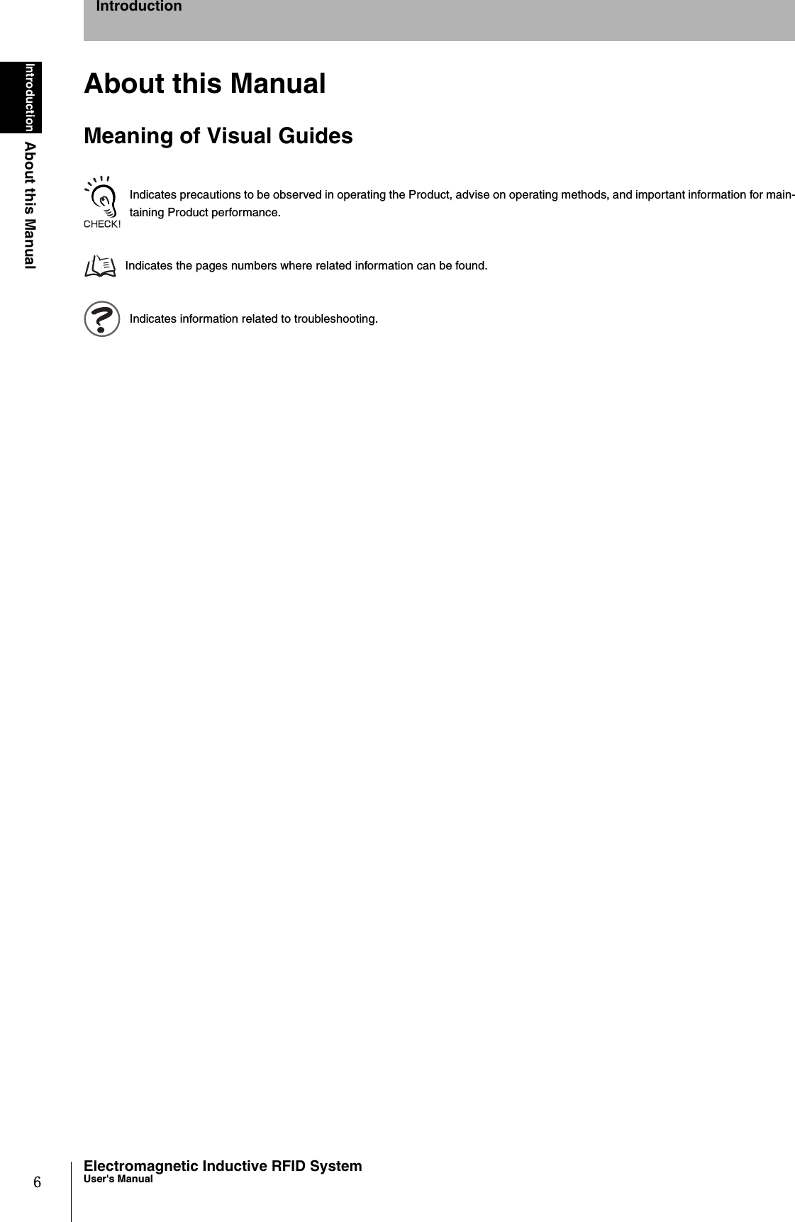
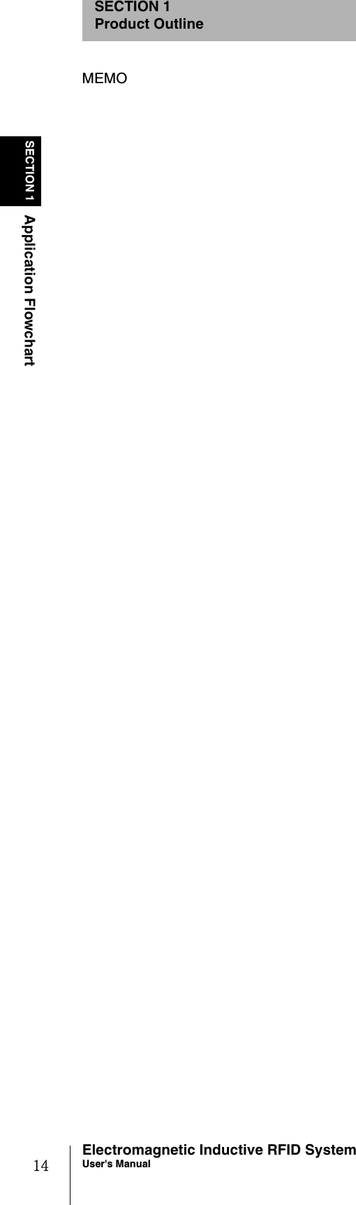
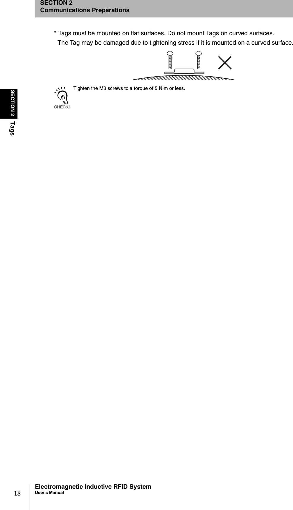
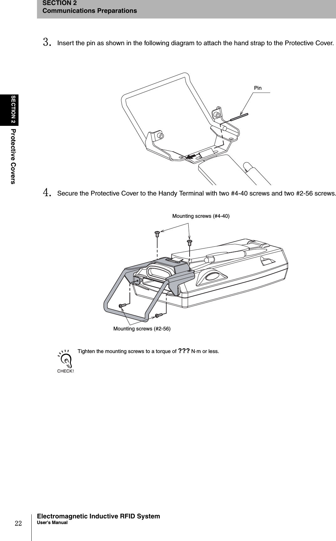
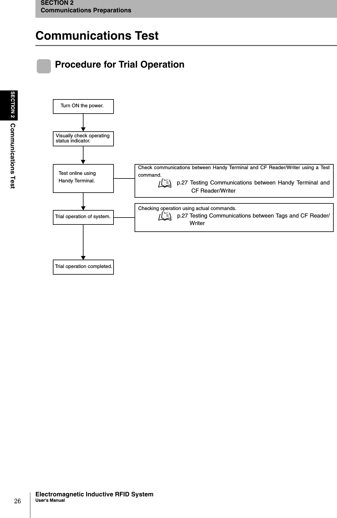
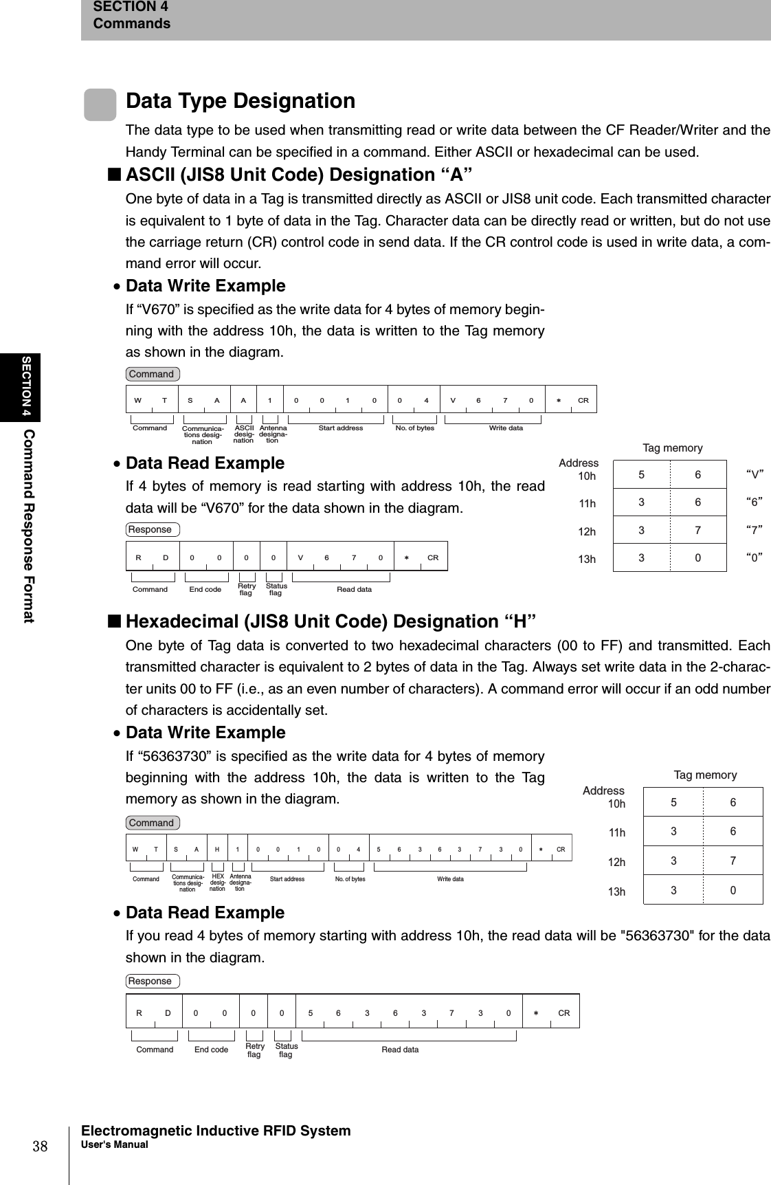
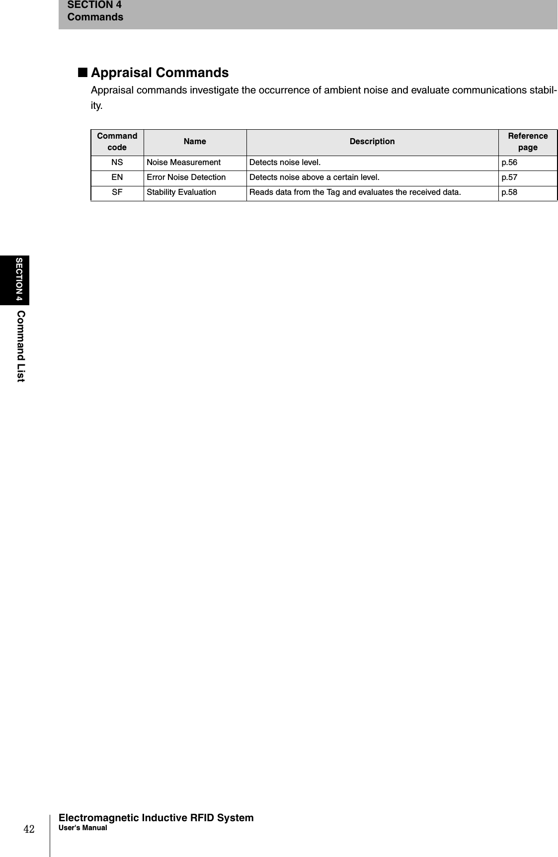
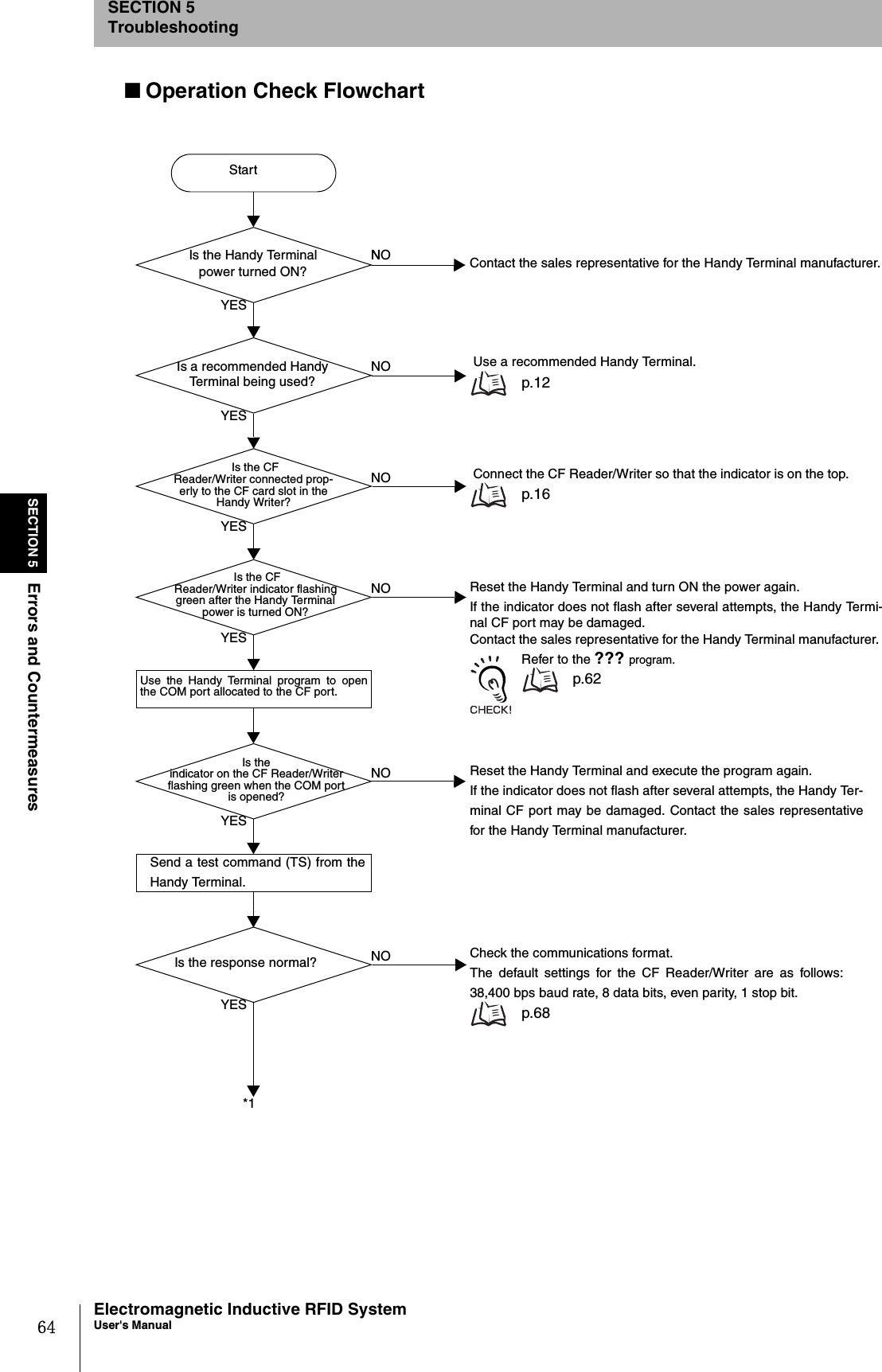
![46SECTION 4Communications CommandsElectromagnetic Inductive RFID SystemUser's ManualSECTION 4CommandsComputation Write (CW)Performs a hexadecimal calculation using the data in Tag memory and the calculation data and writesthe result to the Tag. If an overflow occurs for addition or an underflow occurs for subtraction, the datais not written to the Tag and “1” is returned for the status flag.Example: Writing 2 Bytes of Data, the Result of Subtracting the Subtraction Data “0002” from “0010”,the Data Starting at Address 0001h (Single Auto, Initial Value: “0010”) Send data: CWSAS10001020002*[CR] Receive data: CW0000000E*[CR]This command performs hexadecimal calculations, so specify hexadecimal for all data being handled. Also, set the cal-culation area so that it is contained within one page. If the calculation area is not contained within one page, a com-mand error will occur.p.83 Memory MapCommunications designationSpecifies the method for communicating with a Tag.Refer to Communications Designations for details. p.43Process designation Specifies the calculation method.“A”: Hexadecimal addition“S”: Hexadecimal subtractionAntenna designation Always “1”.Calculation area start addressSpecifies the start address in the Tag memory area for calculating data in four hexadecimal digits.Specification range: 0000h to 007FhNo. of bytes in calculation areaSpecifies the number of bytes of calculation data in the calculation area in two hexadecimal digits.Specification range: 01h to 04hCalculation data Specifies in hexadecimal the number to be used in the calculation.Results data Returns the calculation results data written to the Tag.The data before the calculation was performed will be returned if addition gives an overflow or subtraction gives an underflow. The status flag will be “1” in these cases.2 2 211 4 2㧖CRCommand code "CW" Proc-ess desig-nation Antenna designa-tion Calculation area start address Communica-tions desig-nation No. of bytes in calculation area Specified number of bytes Calculation data Command 2211 2㧖CRCommand code "CW" Retry flag Status flag End code "00" Results data Specified number of bytes Response](https://usermanual.wiki/Omron/6CYCIDV6700104/User-Guide-455260-Page-48.png)
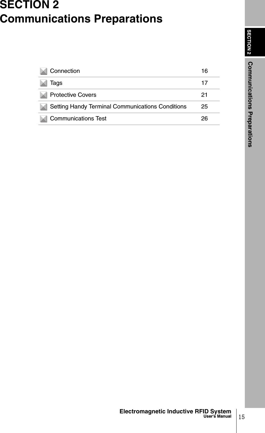
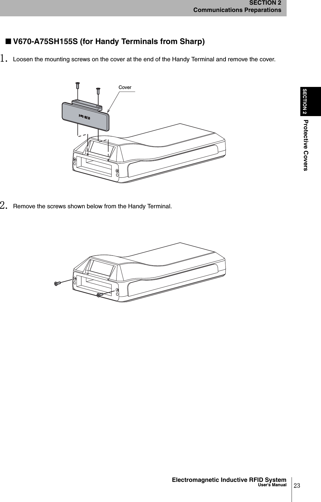
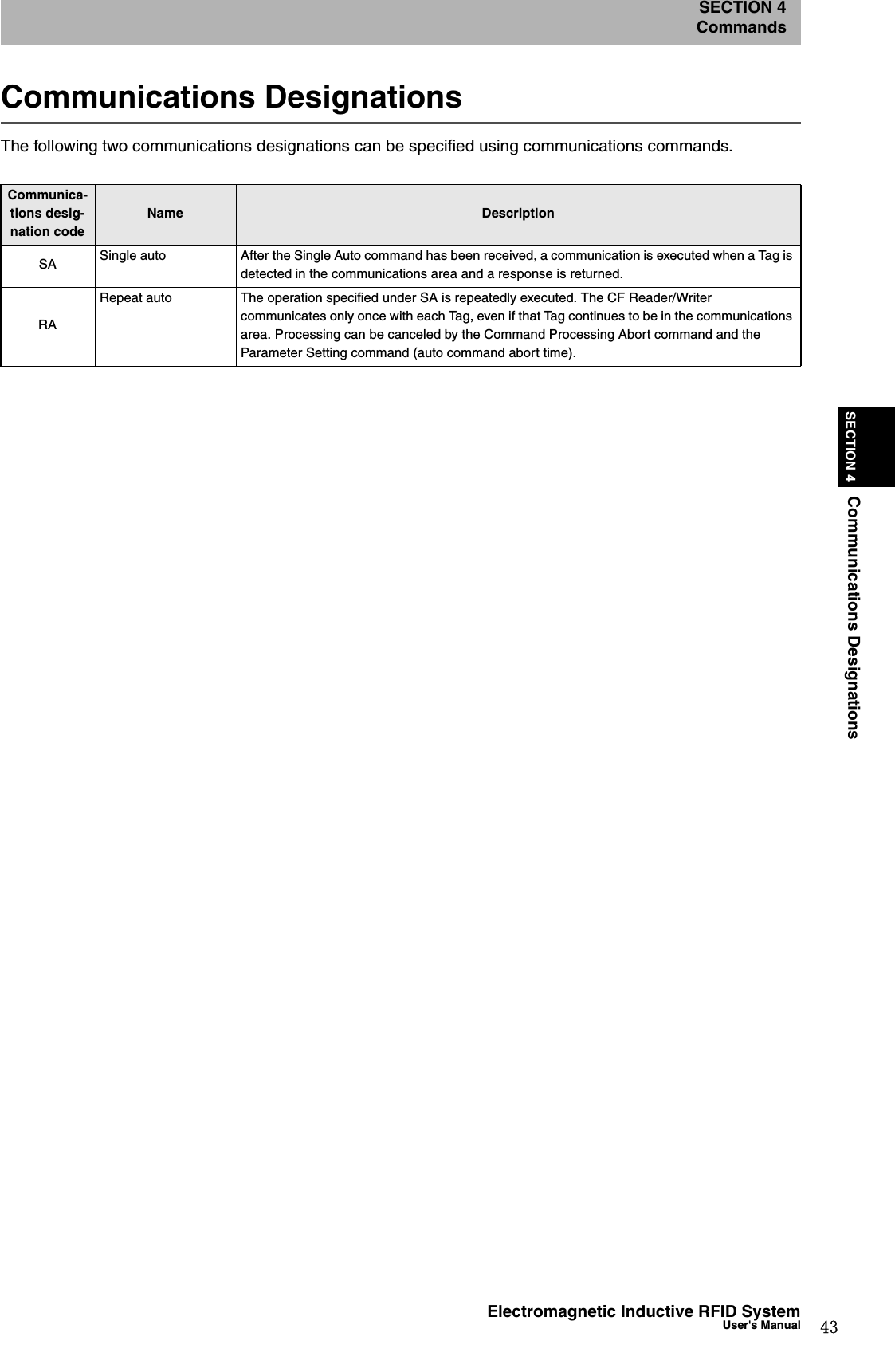
![47Electromagnetic Inductive RFID SystemUser's ManualSECTION 4Communications CommandsSECTION 4CommandsData Fill (DF)Writes one or two bytes of the same data to a specified Tag area. The write data is specified in hexa-decimal.Example: Writing Fill Data “00FF” from Address 0000h to 0007Fh (Single Auto, Writing 2 Bytes) Send data: DFSAW10000007F00FF*[CR] Receive data: DF0000*[CR]The volume of data communications with the Handy Terminal can be reduced by writing fill data to a specified area, sothe use of this command can improve the efficiency of the system.Communications designationSpecifies the method for communicating with a Tag.Refer to Communications Designations for details. p.43Data designation Specifies the size of the write data.“B”: Bytes“W”: Words (2 bytes)Antenna designation Always “1”.Write area start address The address in the Tag for writing data is specified in four hexadecimal digits.Specification range: 0000h to 007FhWrite area end address The end address in the Tag for writing data is specified in four hexadecimal digits.Specification range: 0000h to 007FhWrite data Data written to Tags.Set one byte of hexadecimal if “B” is specified under Data designation, two bytes if “W” is specified.2 2 11 4 42㧖CRCommand code "DF" Data desig-na-tion Antenna designa-tion Write area start address Communica-tions desig-nation Write area end address Write data 1 or 2 bytes worth of data Command 22112㧖CRCommand code "DF" Retry flag Status flag End code "00" Response](https://usermanual.wiki/Omron/6CYCIDV6700104/User-Guide-455260-Page-49.png)
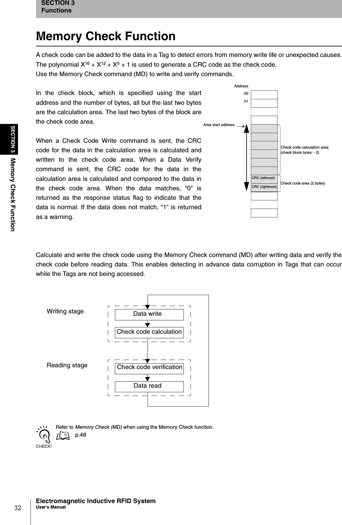
![48SECTION 4Communications CommandsElectromagnetic Inductive RFID SystemUser's ManualSECTION 4CommandsMemory Check (MD)Calculates the check code for the specified block using the polynomial X16 +X12 + X5 + 1, and verifiesthe result against the check code attached to the check block.Example: Adding a Check Code to 4 Bytes of Data from Address 0010h (Single Auto) Send data: MDSAK1001006*[CR] Receive data: MD0000*[CR]* The specified number of bytes will be 6, with 2 bytes of check code attached to 4 bytes of data. Do not write required data in the last two bytes of the area. These two bytes are used to record the check code. Refer to Memory Check Function for details.p.32Communications designationSpecifies the method for communicating with a Tag.Refer to Communications Designations for details. p.43Process designation Specifies the check process.“K”: Check code calculation“C”: Check code verificationAntenna designation Always “1”.Check block start address Specifies the check block start address in four hexadecimal digits.Specification range: 0000h to 007DhNo. of check block bytes Specifies the number of check block bytes in two hexadecimal digits.Specification range: 03h to 80hStatus flag Shows the check code verification result.“0”: Verification normal“1”: Verification error2211 4 22㧖CRCommand code "MD" Proc-ess desig-nation Antenna designa-tion Check block start address Communica-tions desig-nation No. of check block bytes Command 22112㧖CRCommand code "MD" Retry flag Status flag End code "00" Response](https://usermanual.wiki/Omron/6CYCIDV6700104/User-Guide-455260-Page-50.png)
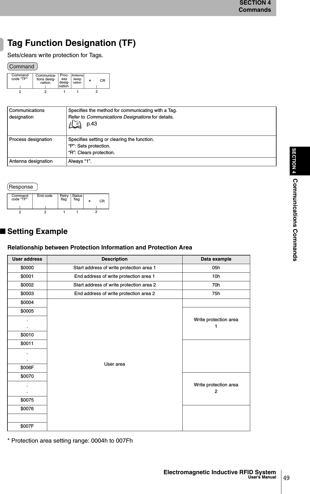
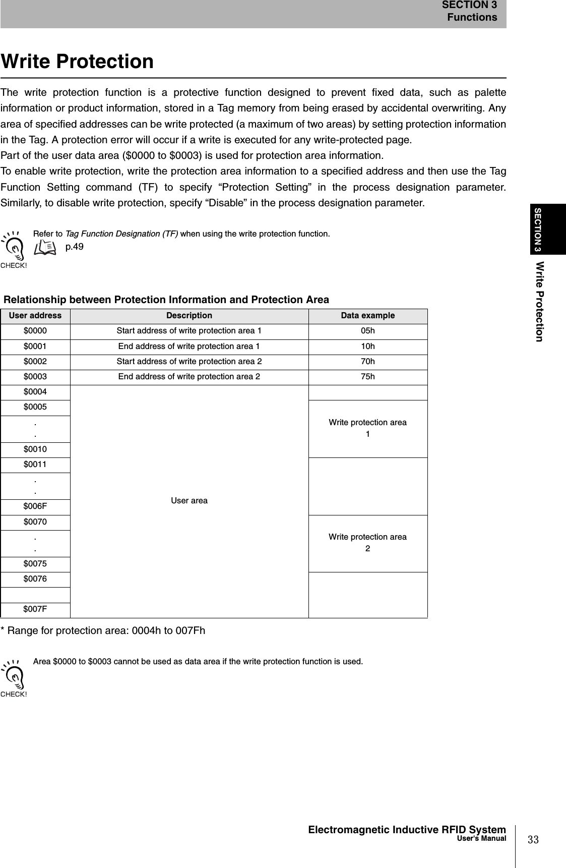
![50SECTION 4Communications CommandsElectromagnetic Inductive RFID SystemUser's ManualSECTION 4Commands•No Write ProtectionWhen write protection is not set for the Tag:Send data: TFSAR1*[CR]Receive data: TF0000*[CR]•Write Protection Specified for One LocationWhen setting write protection for Tag memory addresses 0005h to 0010h(single auto, hexadecimal) Setting Protection Area InformationSend data: WTSAH100000405100510*[CR]Receive data: WT0000*[CR]Setting Write Protection Send data: TFSAP1*[CR]Receive data: TF0000*[CR]When setting write protection for only one location, set the same data to addresses 0002h and 0003h and to addresses0000h and 0001h.•Write Protection Specified for Two LocationsWhen setting write protection for Tag memory addresses 0005h to 0010h and addresses 0070h to0075h (single auto, hexadecimal) Setting Protection Area InformationSend data: WTSAH100000405107075*[CR]Receive data: WT0000*[CR] Setting Write Protection Send data: TFSAP1*[CR]Receive data: TF0000*[CR]Refer to Write Protection for details on write protection.p.33](https://usermanual.wiki/Omron/6CYCIDV6700104/User-Guide-455260-Page-52.png)
![51Electromagnetic Inductive RFID SystemUser's ManualSECTION 4Communications CommandsSECTION 4CommandsID Read (ID)Reads the Tag’s user ID.Example: Reading Tag User ID (Single Auto, User ID: “12345678”) Send data: IDSAH1*[CR] Receive data: ID000012345678*[CR]All Tags store their own unique ID. The ID Read command can be used for very fast communications if all that isrequired is to detect whether or not there is a Tag in the communications area.Communications designationSpecifies the method for communicating with a Tag.Refer to Communications Designations for details. p.43Data designation Always “H” (hexadecimal).Antenna designation Always “1”.Read data User ID data read from a Tag.00000000 to 3FFFFFFFThe leftmost 2 bits are system bits and are always 0.22112㧖CRCommand code "ID" Data desig-na-tion Antenna designa-tion Communica-tions desig-nation Command 2211 2㧖CRCommand code "RD" Retry flag Status flag End code "00" Specified number of bytes Read data Response](https://usermanual.wiki/Omron/6CYCIDV6700104/User-Guide-455260-Page-53.png)
![52SECTION 4Communications SubcommandElectromagnetic Inductive RFID SystemUser's ManualSECTION 4CommandsCommunications SubcommandThe communications subcommand is used in combination with communications commands. Nocommunications processing is performed with Tags when the communications subcommand is used alone.Command Processing Abort (AA)Aborts processing of a command being executed and returns to the command standby status. Com-mand Processing Abort can be executed during the processing of any command.When command processing has been aborted after a Tag is detected, the status flag will be “2”.Example: Aborting Command Processing during Execution Send data: AA01*[CR] Receive data: AA0000*[CR]Process designation Always “0”.Antenna designation Always “1”.2112㧖CRCommand code "AA" Proc-ess desig-nation Antenna desig-nation Command 22112㧖CRCommand code "AA" Retry flag Status flag End code Response](https://usermanual.wiki/Omron/6CYCIDV6700104/User-Guide-455260-Page-54.png)
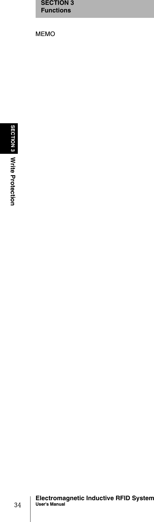
![53Electromagnetic Inductive RFID SystemUser's ManualSECTION 4Controller Control CommandsSECTION 4CommandsController Control CommandsParameter Setting (SP)This command sets communications conditions by setting the parameters in the CF Reader/Writer.* The parameter number for the parameter data is the number specified in the lower digit of the processcode. Set the parameter data within the setting range given for the parameter number specified in thelower digit of the process code.Example: Setting Character Interval Monitoring Time to 500 ms Send data: SP010500*[CR] Receive data: SP0000*[CR]Process code (upper digit) Specifies the process to be performed for the parameter.“0”: Change“1”: Read“9”: Initialize (default setting)Process code (lower digit) Specifies the parameter.“4”: Auto command abort time“C”: Write verificationParameter data (only when changing the parameter)Parameter* Setting range4Set two decimal digits 01 to 60 (unit: 1 s). A command error will occur if 00 is set. Default is 10 s.C 0: OFF, 1: ON, Default is 1 (Write varification enabled)2 22㧖CRCommand code "SP" Parameter data (only when changing) Process code (Upper) (Lower)Command 2211 2㧖CRCommand code "SP" Retry flag Parameter data (only when reading) Status flag End code Response](https://usermanual.wiki/Omron/6CYCIDV6700104/User-Guide-455260-Page-55.png)
![54SECTION 4Controller Control CommandsElectromagnetic Inductive RFID SystemUser's ManualSECTION 4CommandsReset (XZ)Resets the CF Reader/Writer.No response is sent. A response is not returned for the Reset (XZ) command. The indicator will flash green when this command is received.Check the indicator after sending this command to confirm that it has been received. Example: Resetting the CF Reader/Writer Send data: XZ*[CR] Receive data: None22㧖CRCommand code "XZ" Command Response](https://usermanual.wiki/Omron/6CYCIDV6700104/User-Guide-455260-Page-56.png)
![55Electromagnetic Inductive RFID SystemUser's ManualSECTION 4Host CommandsSECTION 4CommandsHost CommandsTest (TS)Returns the message sent by the Handy Terminal directly as the response. The Test command is usedto test communications between the CF Reader/Writer and a Handy Terminal.Example: Sending Message Data “OMRON” from the Handy Terminal Send data: TSOMRON*[CR] Receive data: TS0000OMRON*[CR]Version Information (VS)Reads the CF Reader/Writer model information, software version, and creation date and time.Example: Reading the CF Reader/Writer Software Version Send data: VS*[CR] Receive data: VS0000V670-CF01$00000000;1.00;2004/04/01*[CR]Message data Any character string for testing communications.22㧖CRCommand code "TS" Message data Command 2211 2㧖CRCommand code "TS" Retry flag Status flag End code Message data Response 22㧖CRCommand code "VS" Command 2211 2㧖CRCommand code "VS" Retry flag Status flag End code Model information; software version; creation date and time Response](https://usermanual.wiki/Omron/6CYCIDV6700104/User-Guide-455260-Page-57.png)
![56SECTION 4Appraisal CommandsElectromagnetic Inductive RFID SystemUser's ManualSECTION 4CommandsAppraisal CommandsIf errors are frequent during communications with Tags, one of the causes may be ambient noise. Theappraisal commands are used to investigate whether or not noise is the cause of errors. It can also be used tocheck noise generation at installation sites before installing V670-series Tags or Antennas and Controllers. Even if read results are normal, reception waveforms may exhibit interference. These commands can be usedto check for noise at the waveform level to provide more detailed information on the actual status of thewaveforms.Noise Measurement Command (NS)Investigates the noise level when commands are received.Example: Investigating Ambient Noise Level Send data: NS*[CR] Receive data: NS00000A*[CR]Noise evaluation result The noise level is evaluated as the maximum absolute value in the measured data.“A”: Low noise level (0.0 V to 2.0 V); indicator will light green.“B”: High noise level (2.0 V to 3.3 V); indicator will flash red.22㧖CRCommand code "NS" Command 221112㧖CRCommand code "NS" Retry flag Status flag End code Result of noise level measure-ment Response](https://usermanual.wiki/Omron/6CYCIDV6700104/User-Guide-455260-Page-58.png)
![57Electromagnetic Inductive RFID SystemUser's ManualSECTION 4Appraisal CommandsSECTION 4CommandsError Noise Detection Command (EN)The Error Noise Detection command detects noise above a specified level. When deciding where to mount Tags and Antennas, use this command to investigate where the noiselevel is high.* When both data 1 and data 2 are omitted, noise detection is performed using the previously specifiedvalues. If they are omitted the first time this command is set after turning ON the power supply, thedefault settings will be used for noise detection. Example: Detecting Noise at 3.3 V or Greater during a Period of 5 s Send data: EN330005*[CR] Receive data: EN0000020*[CR]The Error Noise Detection command can be canceled using the Command Processing Abort command (AA), becauseno response is given for a set period of time. p.52Data 1Error noise levelSpecifies the error noise level in two decimal digits. (This setting may be omitted*).Specification range: 00 to 33 (× 0.1 V)Default: 2.0 VWhen “00” is specified: 100%Data 2Measurement timeSpecifies the error noise measurement time in four decimal digits. (This setting may be omitted*).Specification range: 0000 to 0100 sDefault: 0060 sWhen “0000” is specified: Noise level when command is received is returned in the response.Judgment result The noise level is evaluated as the maximum absolute value in the measured data.“0”: Normal; indicator will light green.“1”: Error; indicator will flash red.Maximum noise level Gives the maximum noise level (V) detected during the measurement period in two decimal digits.Unit: 0.1 V2242㧖CR24 2㧖CRCommand code "EN" Data 1 Data 2 Command code "EN" Data 2 Command 22 2㧖CR22㧖CRCommand code "EN" Data 1 Command code "EN" Specifying Data 1 and Data 2 Omitting Data 1Omitting Data 2 Omitting Data 1 and Data 22211 2㧖CR12Command code "EN" Retry flag Status flag End code Judge-ment result Maximum noise level Response](https://usermanual.wiki/Omron/6CYCIDV6700104/User-Guide-455260-Page-59.png)
![58SECTION 4Appraisal CommandsElectromagnetic Inductive RFID SystemUser's ManualSECTION 4CommandsStability Evaluation Command (SF)The Stability Evaluation command evaluates the stability of received data. Data is read from the Tag, the received data is evaluated, and the evaluation results are returned in theresponse and through the indicator. Forty bytes of data is read starting from address 0000h. Example: Investigating Communications Stability Send data: SF*[CR] Receive data: SF0000A*[CR]Evaluation CriteriaResponse Meaning Evaluation criteria IndicatorA Excellent Min. 80% within distribution range Lit green.B Good Min. 60% within distribution range Flashing green.C No good Less than 60% within distribution range Flashing red.2 2㧖CRCommand code "SF" Command 2211 2㧖CR1Command code "SF" Retry flag Status flag End code Judge-ment result Response](https://usermanual.wiki/Omron/6CYCIDV6700104/User-Guide-455260-Page-60.png)
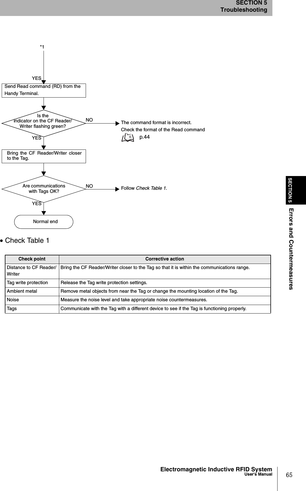
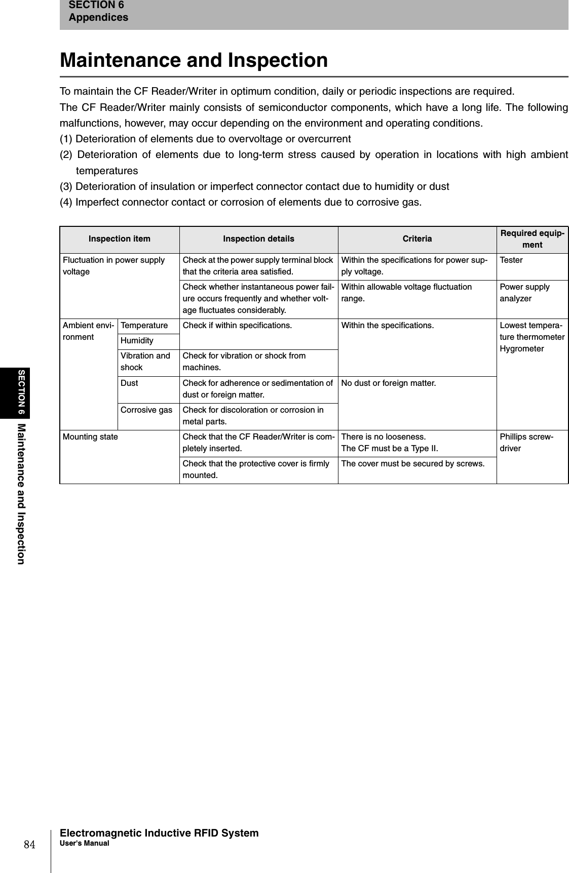
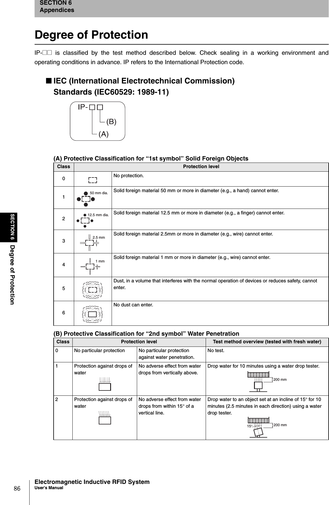
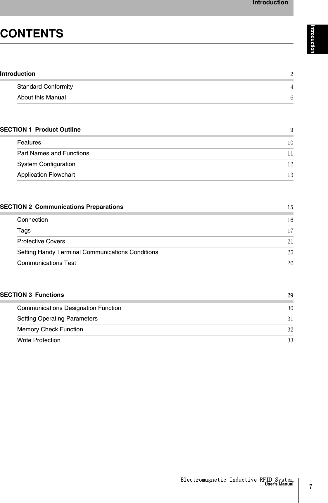
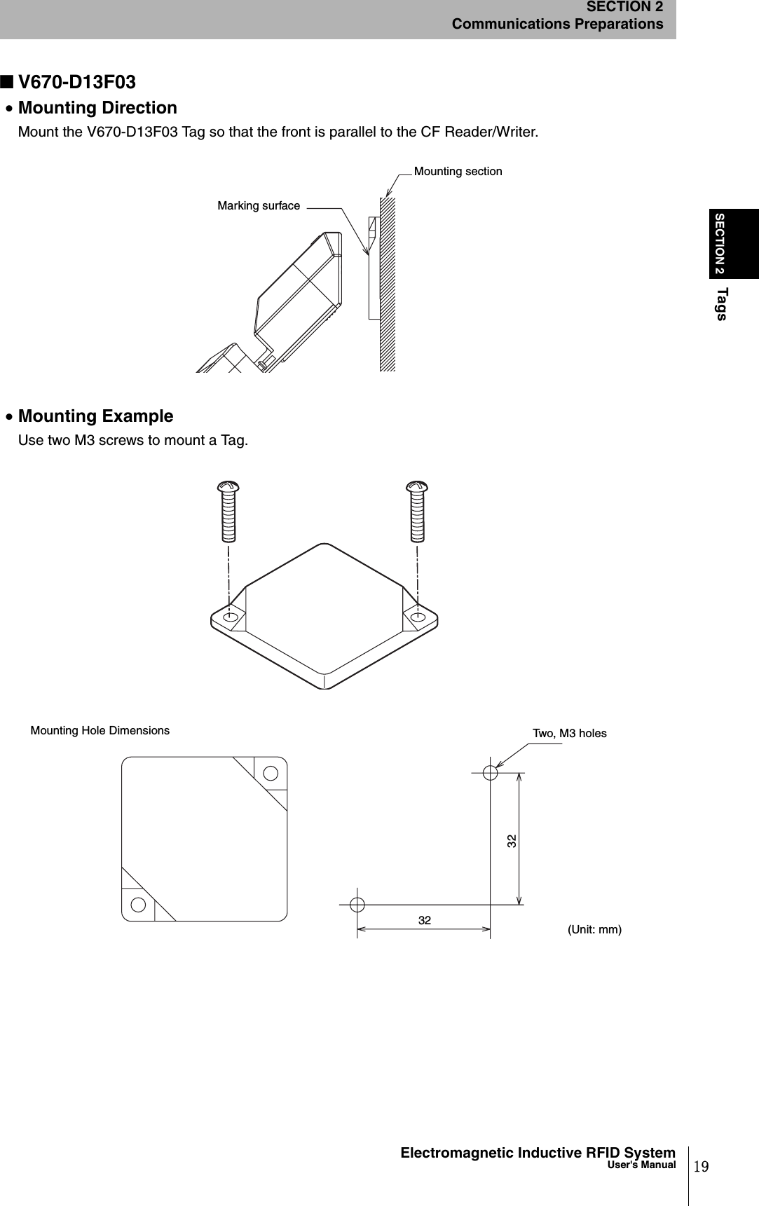
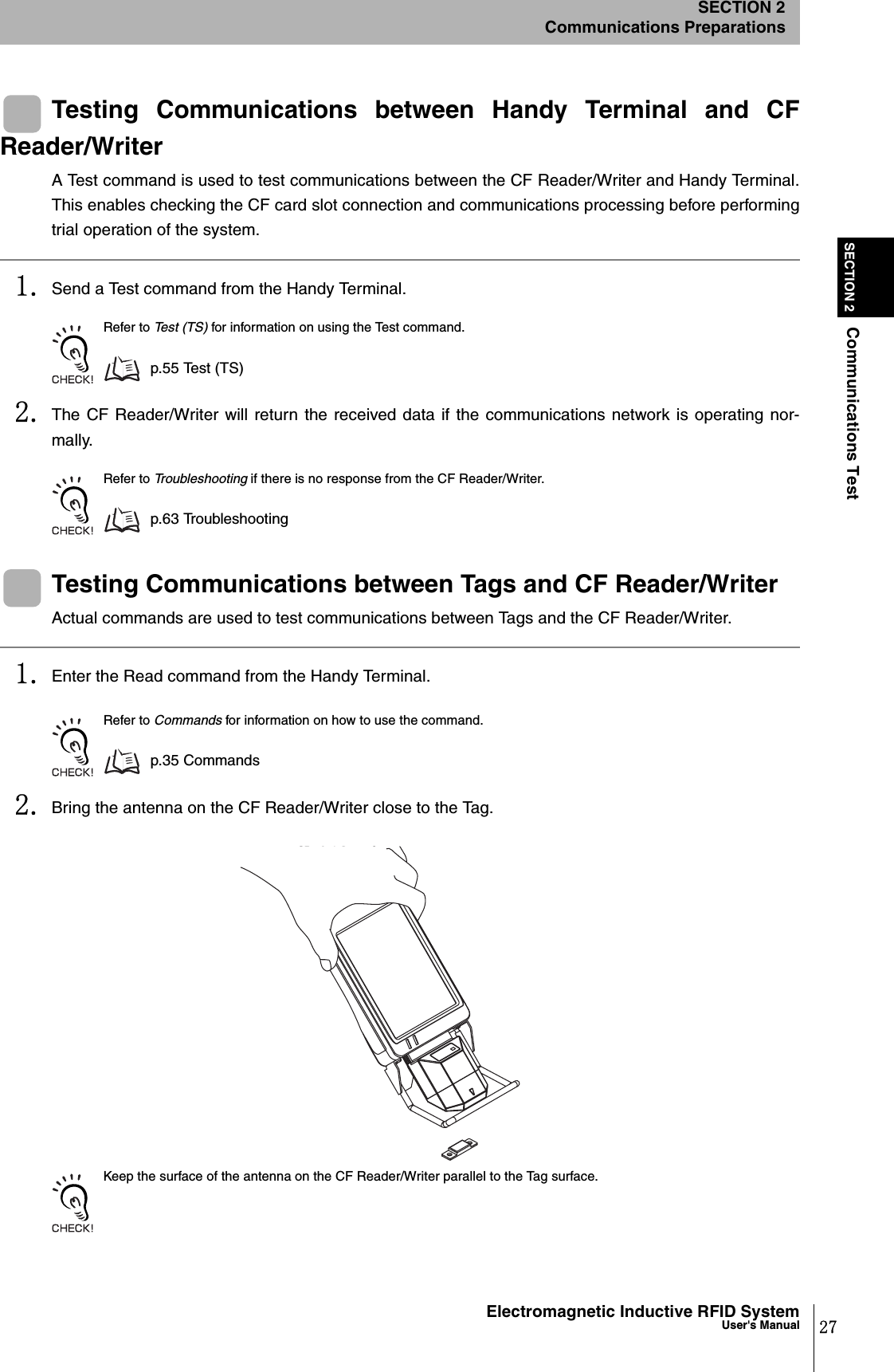
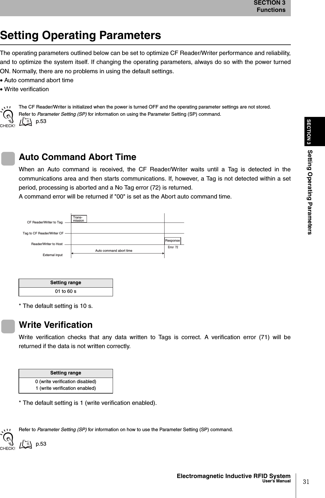
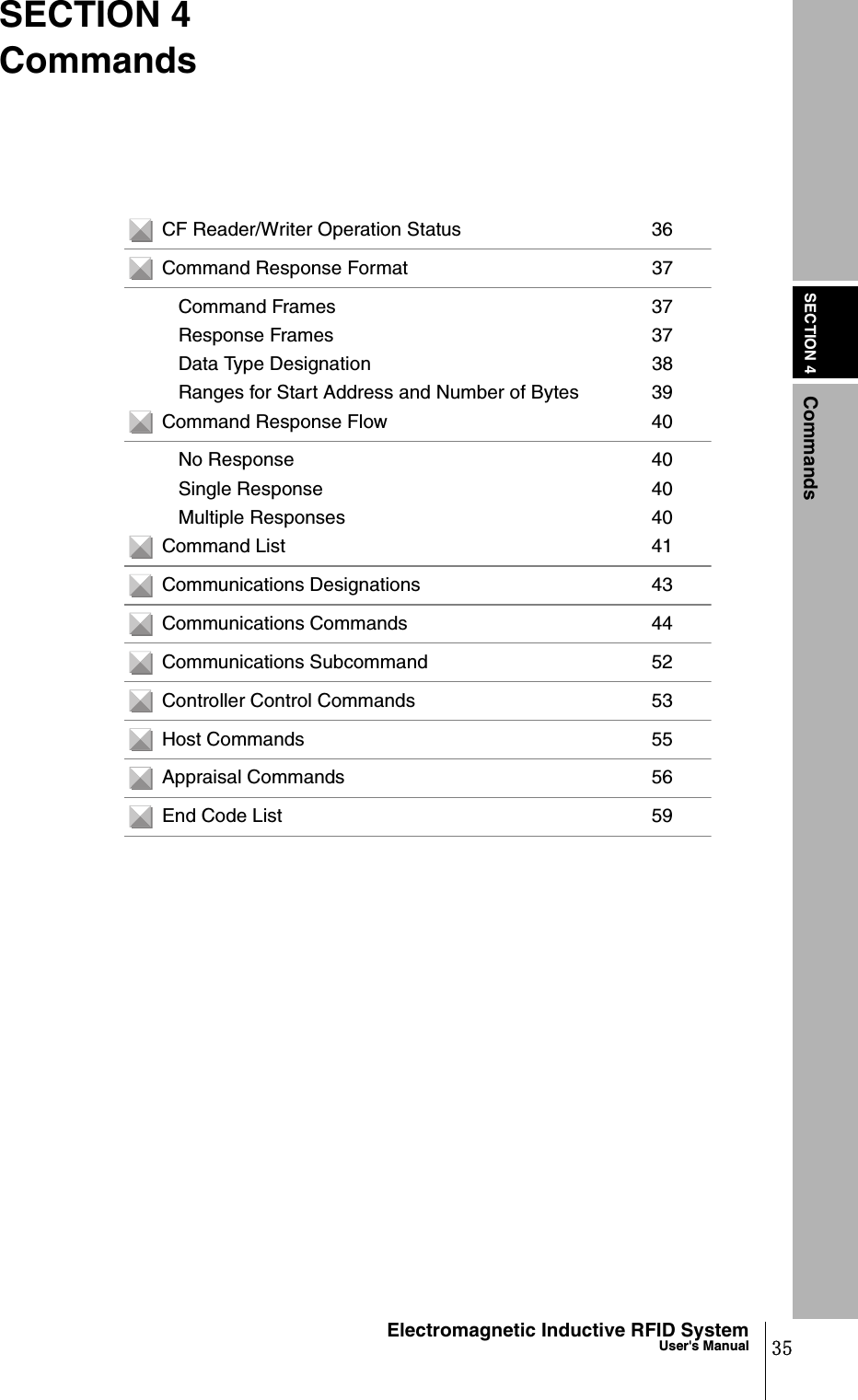
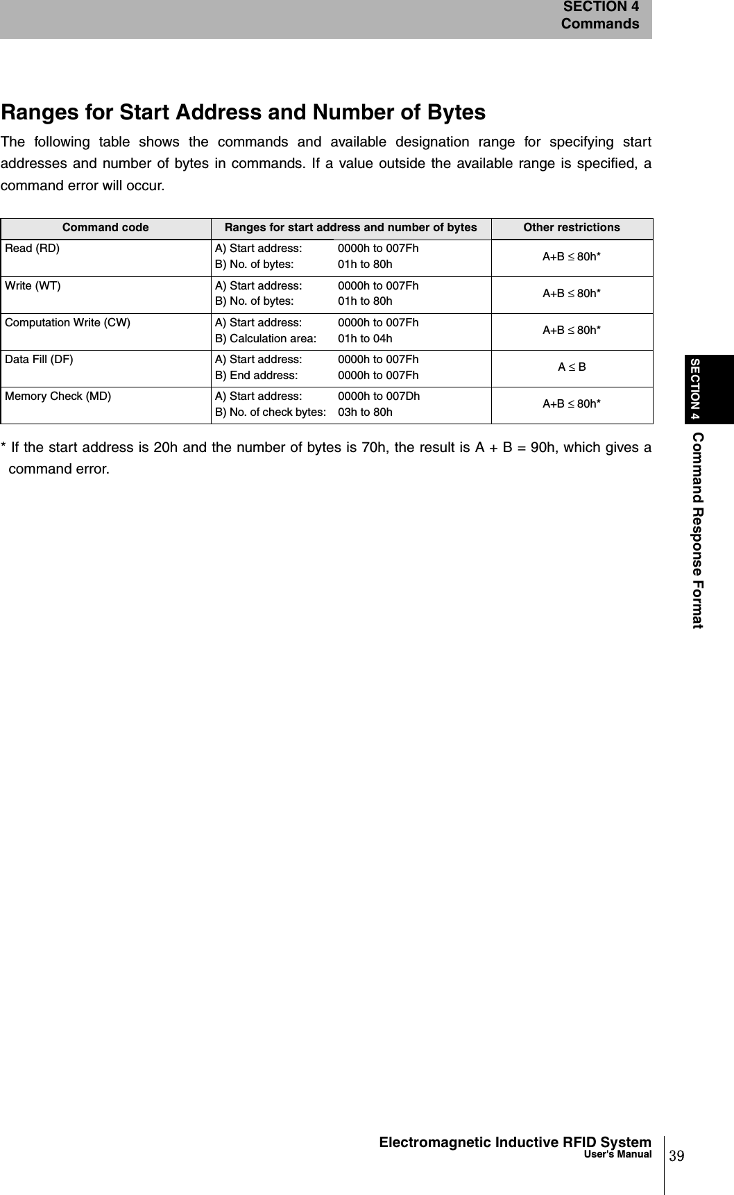
![SECTION 6Table of JIS8 Unit Code (ASCII)SECTION 6Appendices85Electromagnetic Inductive RFID SystemUser's ManualTable of JIS8 Unit Code (ASCII)LeftdigitsRight digitsb8 to b5 0000 1001 0010 0011 0100 0101 0110 0111 1000 1101 1010 1011 1100 1101 1110 1111b4 to b1 ColRow 0 1 2 3 4 5 6 7 8 9 10 11 12 13 14 150000 0NUL TC7 (DLE) (SP) 0 @ P ` p Unde-fined -タミ0001 1TC1 (SOH) DC1!1AQaq 。 アチム0010 2TC2 (STX) DC2"2BRbr 「 イツメ0011 3TC3 (ETX) DC3#3CScs 」 ウテモ0100 4TC4 (EOT) DC4$4DTd t 、 エトヤ0101 5TC5 (NEQ) TC8 (NAK) % 5 E U e u . オナユ0110 6TC6 (ACK) TC9 (SYN) & 6 F V f v ヲ カニヨ0111 7BEL TC10 (ETB) ' 7 G W g w ァ キヌラ1000 5FE0 (BS) CAN ( 8 H X h x ィ クネリ1001 9FE1 (HT) EM ) 9 I Y i y ゥ ケノル1010 10 FE2 (LF) SUB * : J Z j z ェ コハレ1011 11 FE3 (VT) ESC + ; K [ k { ォ サヒロ1100 12 FE4 (FF) IS4 (FS) , < L \ l | ャ シフワ1101 13 FE5 (CR) IS3 (GS) - = M ] m } ュ スヘン1110 14 SO IS2(RS) . > N ^ n  ̄ ョ セホ゛1111 15 SI IS1(US) / ? O _oDEL ッソマ°UndefinedNote: The character in the 5th column, 12th row is backslash ( / ) in ASCII.UndefinedUndefinedUndefined](https://usermanual.wiki/Omron/6CYCIDV6700104/User-Guide-455260-Page-87.png)