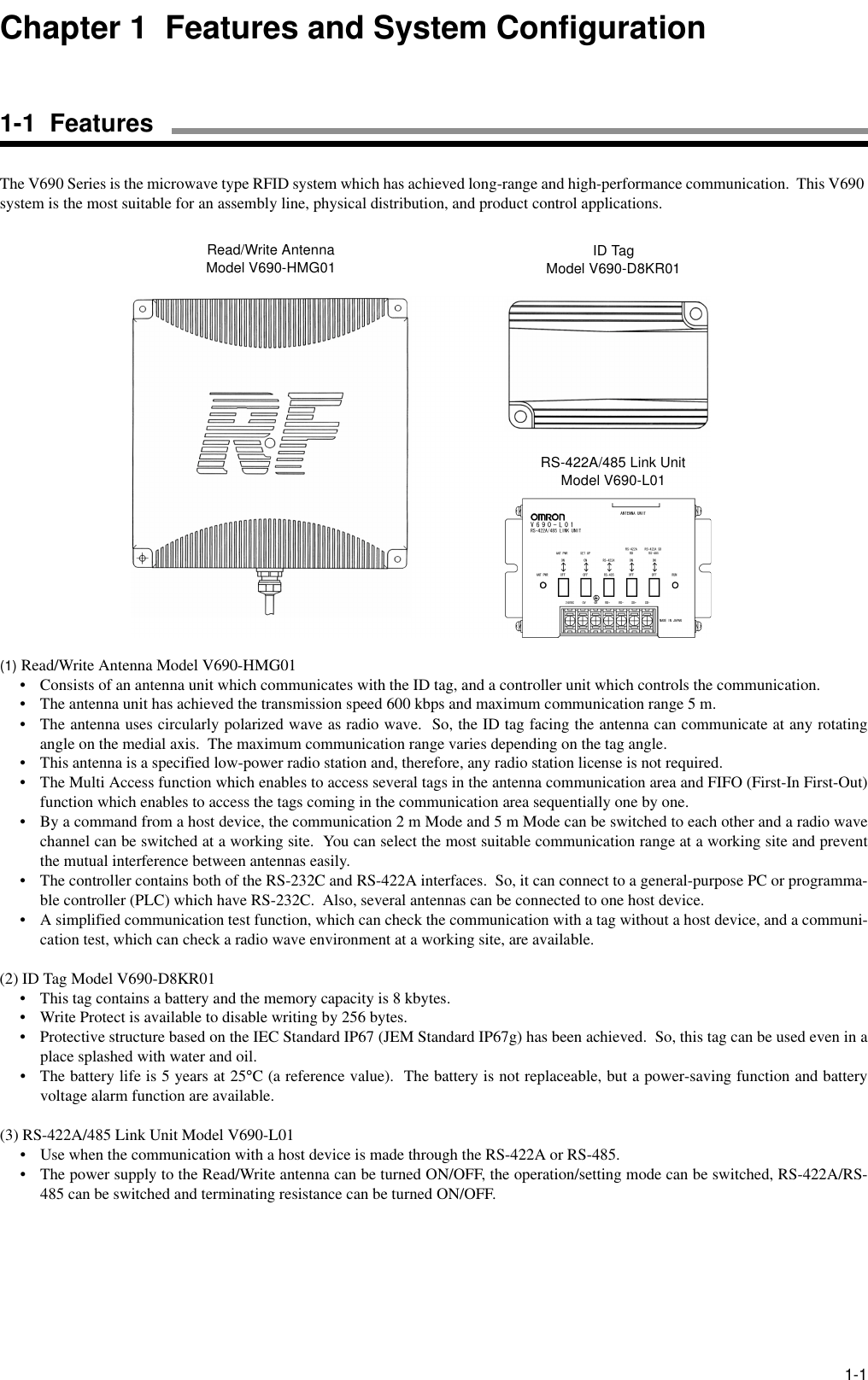
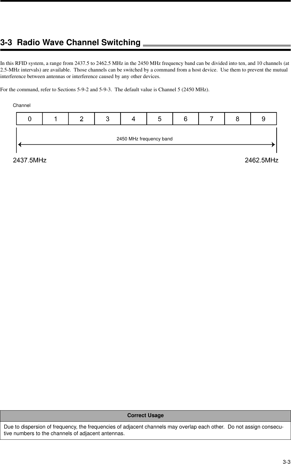
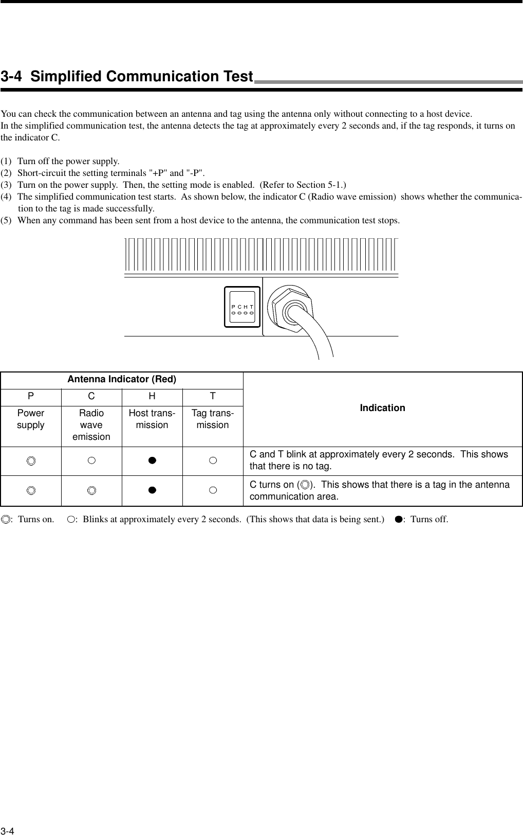
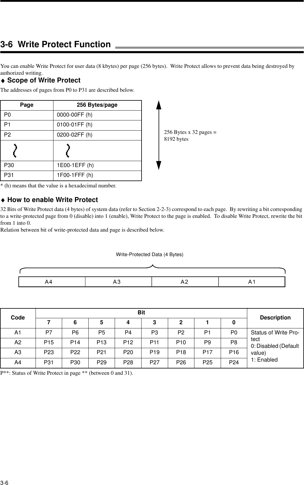
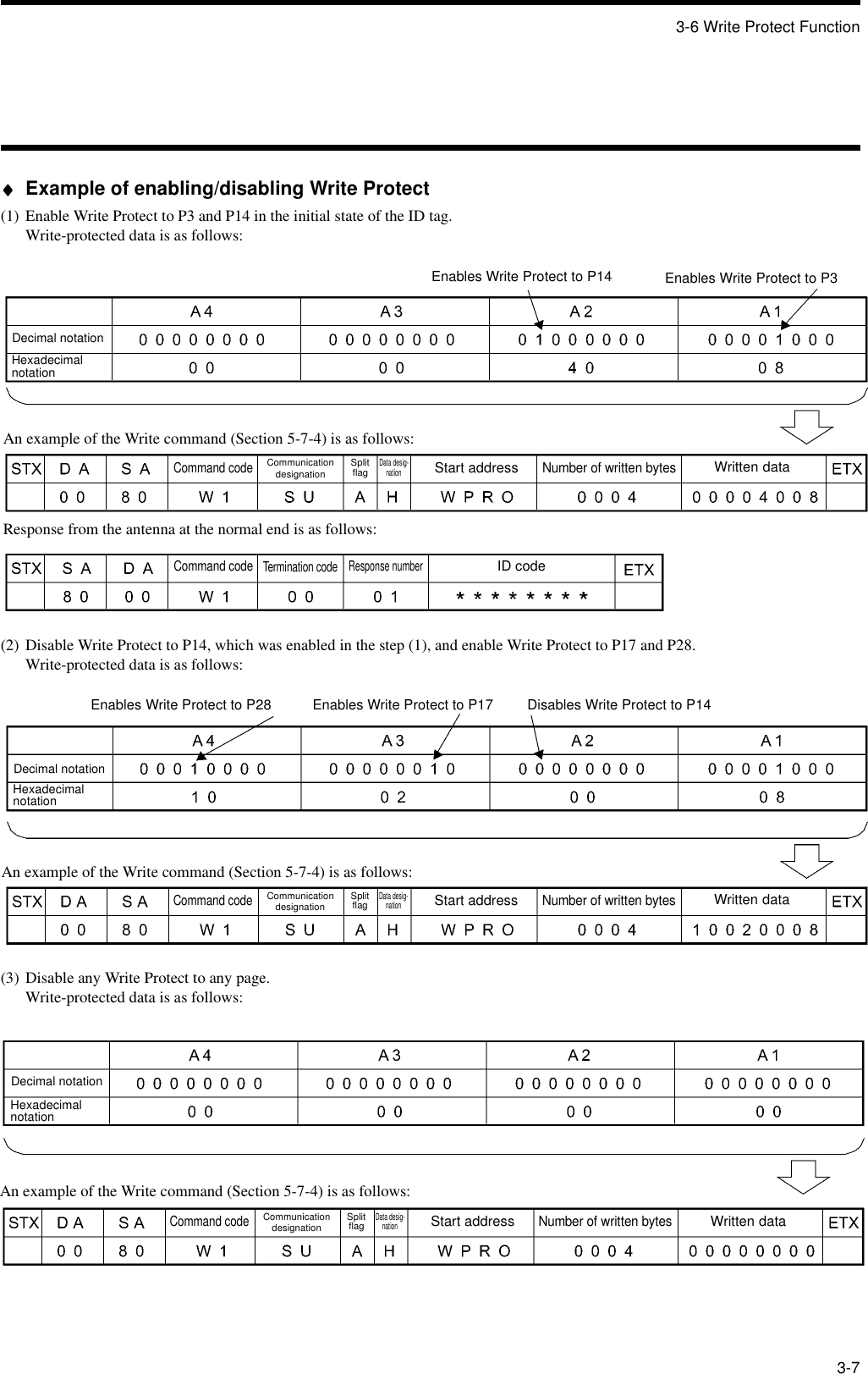
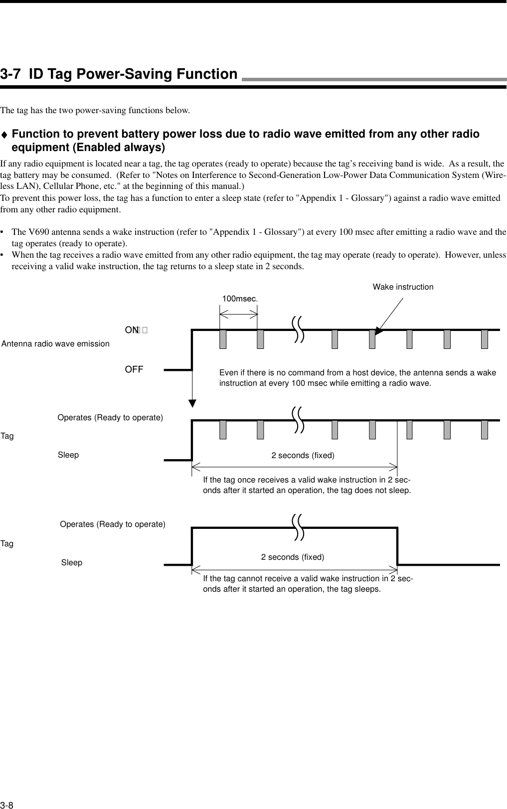
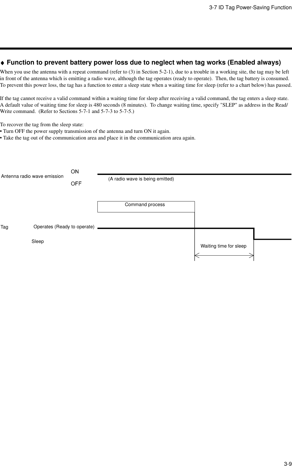
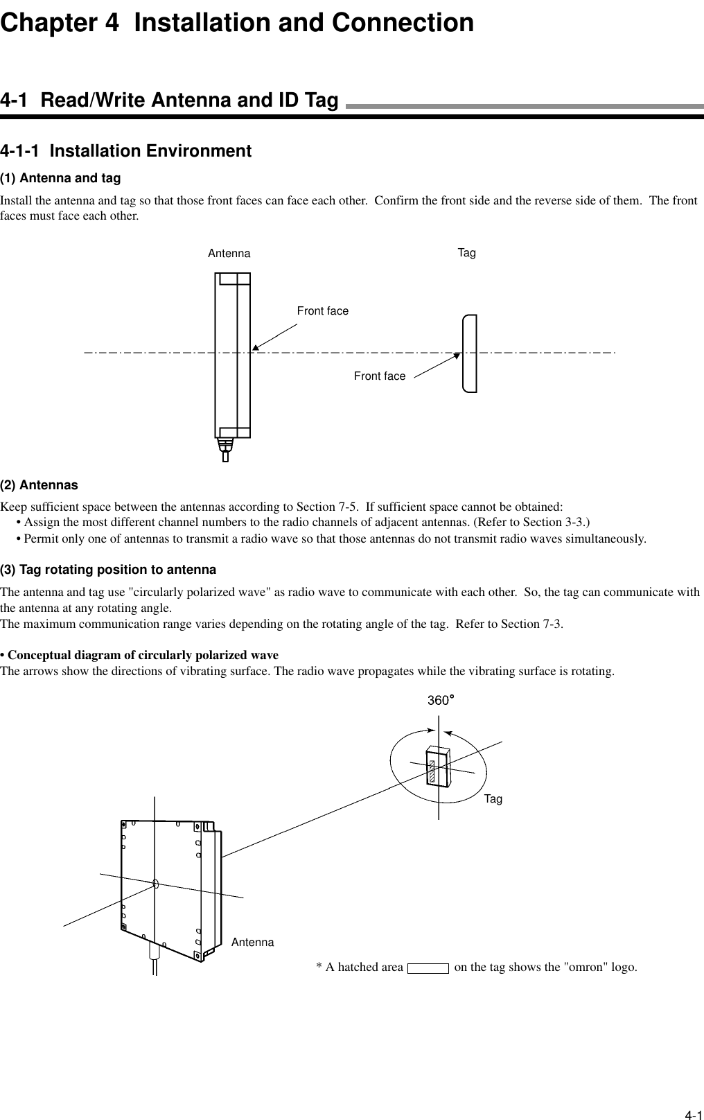
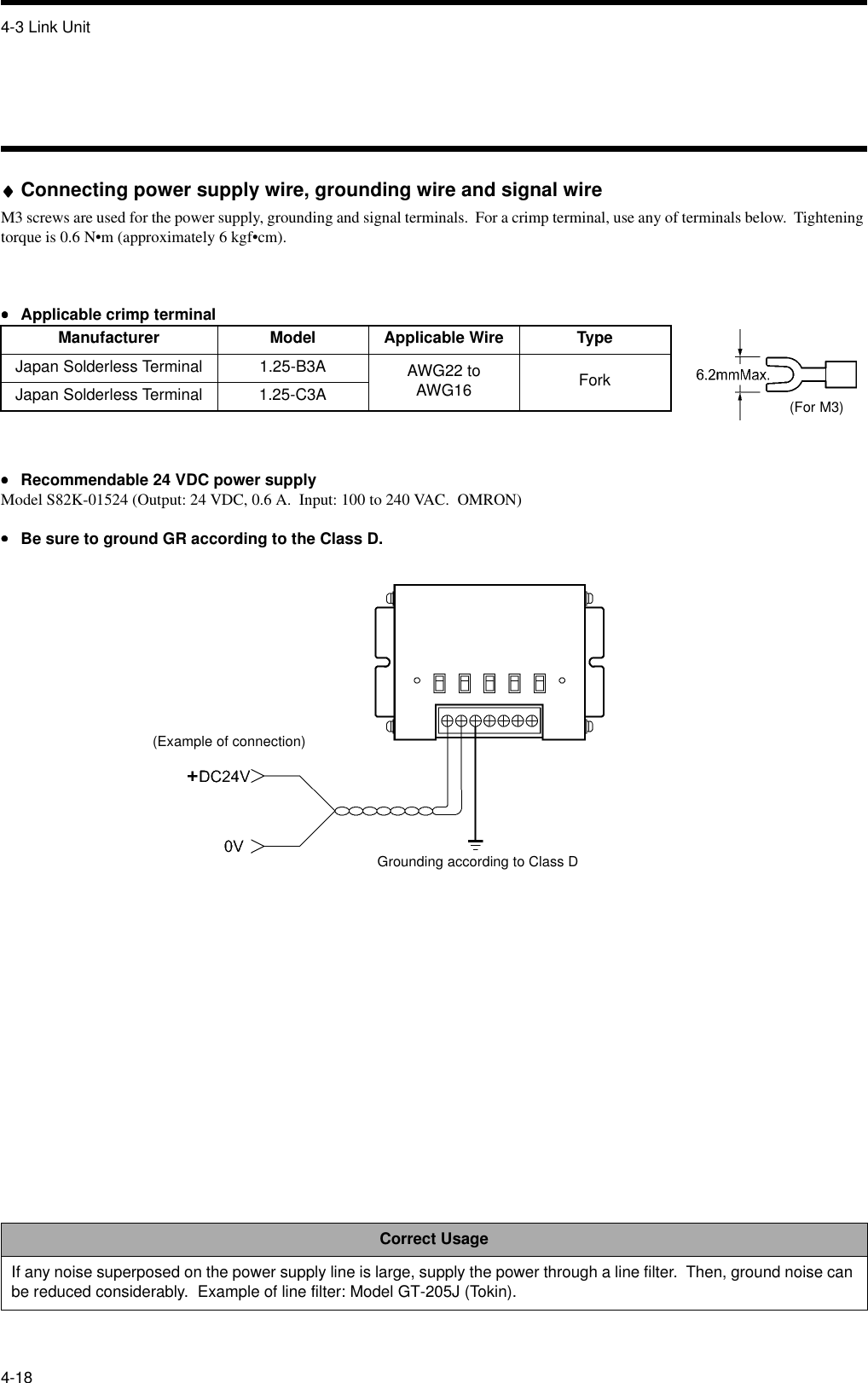
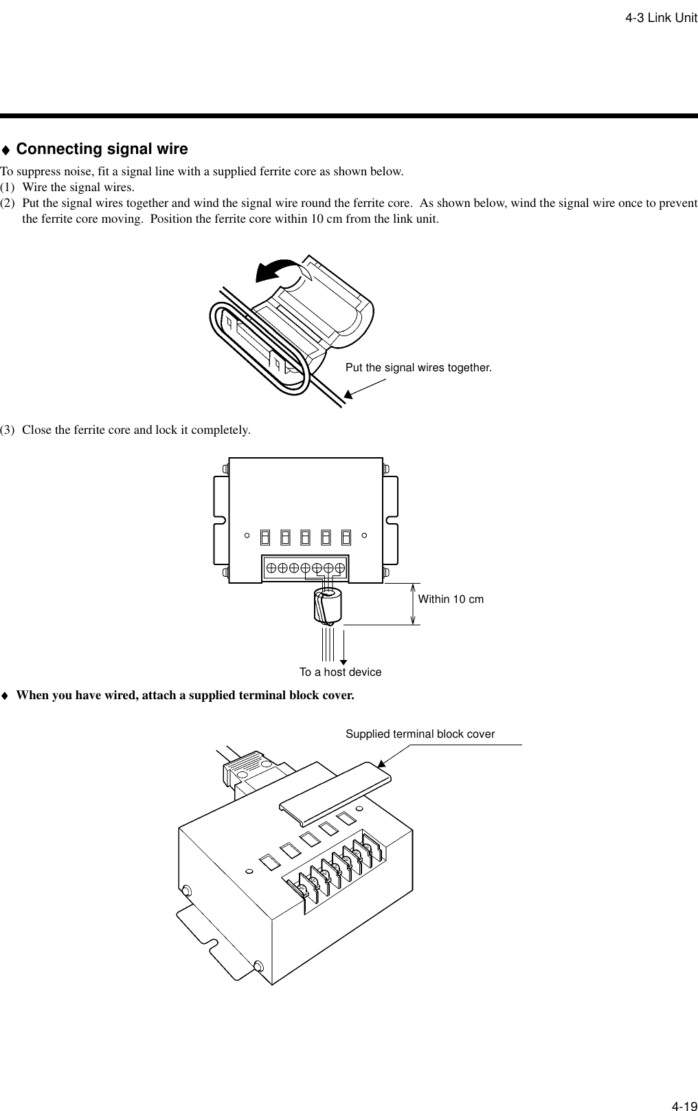
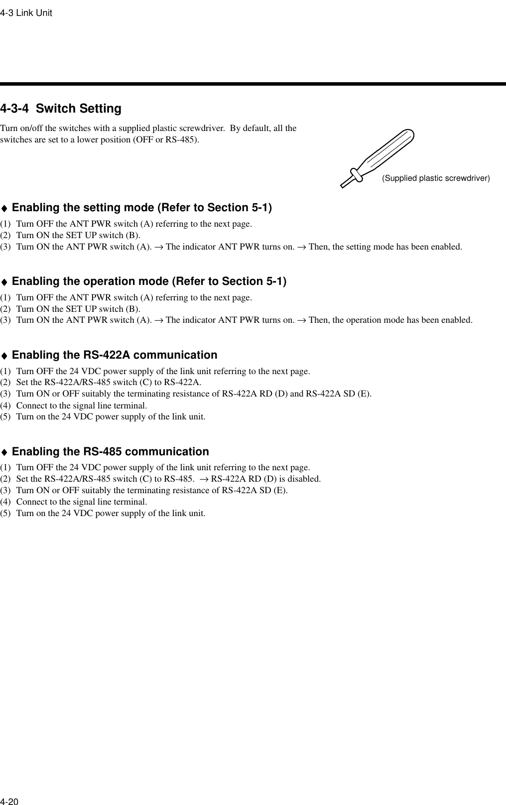
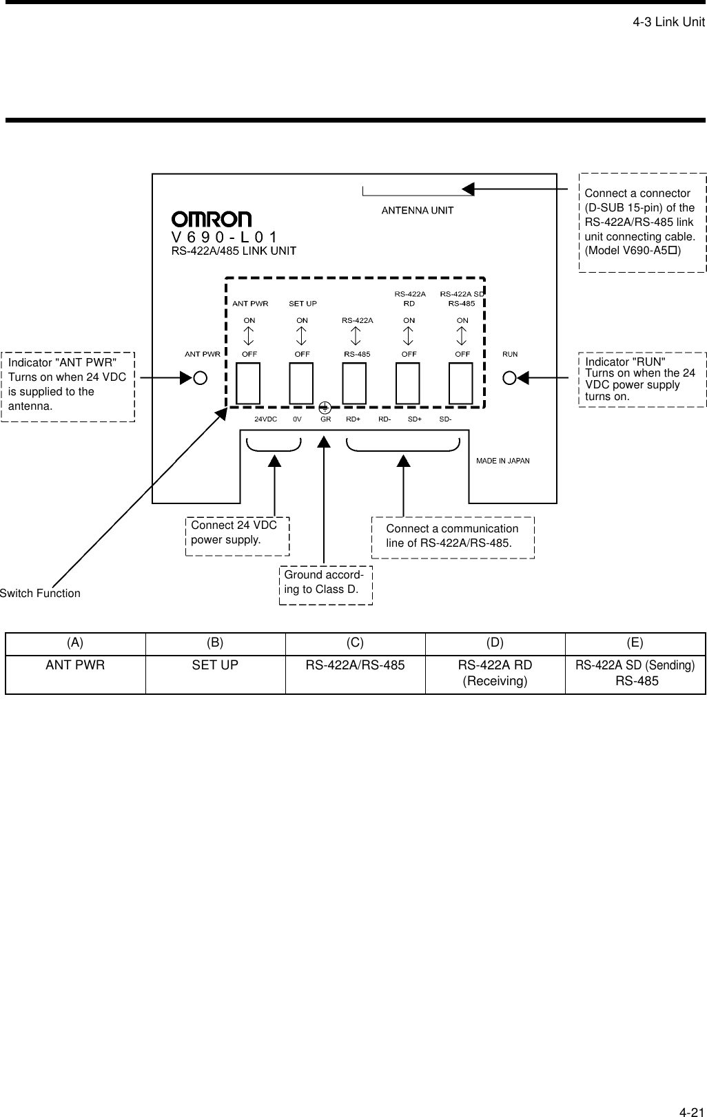
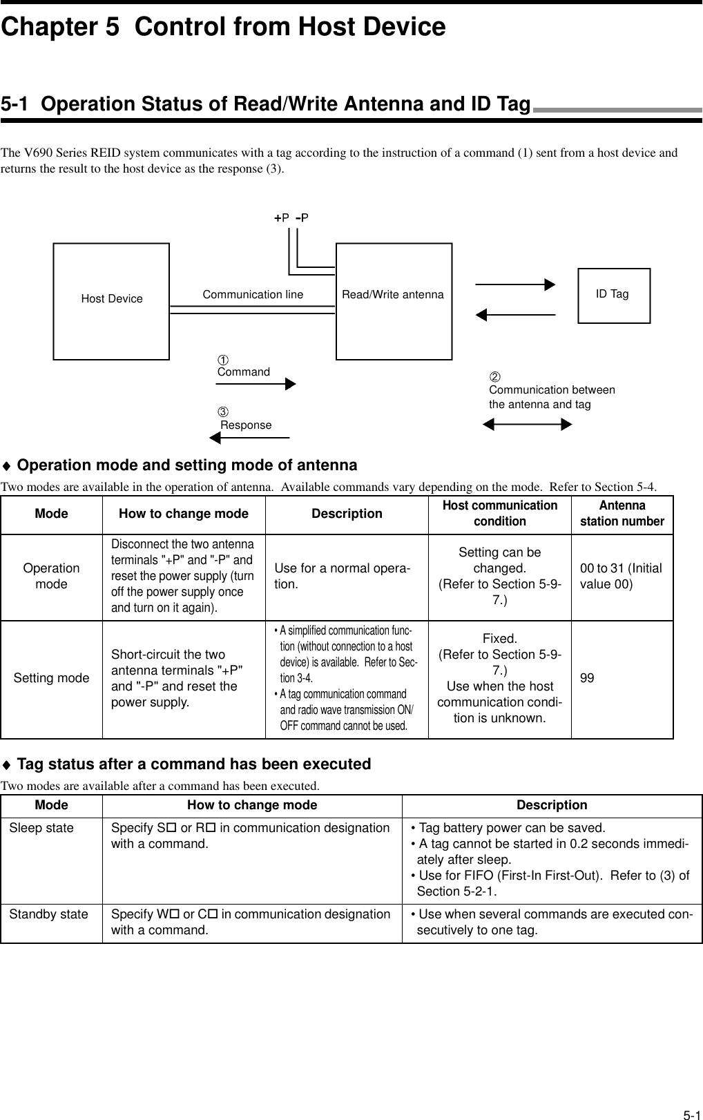
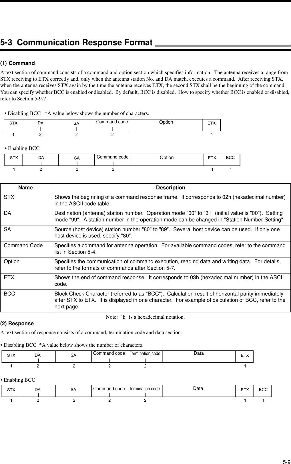
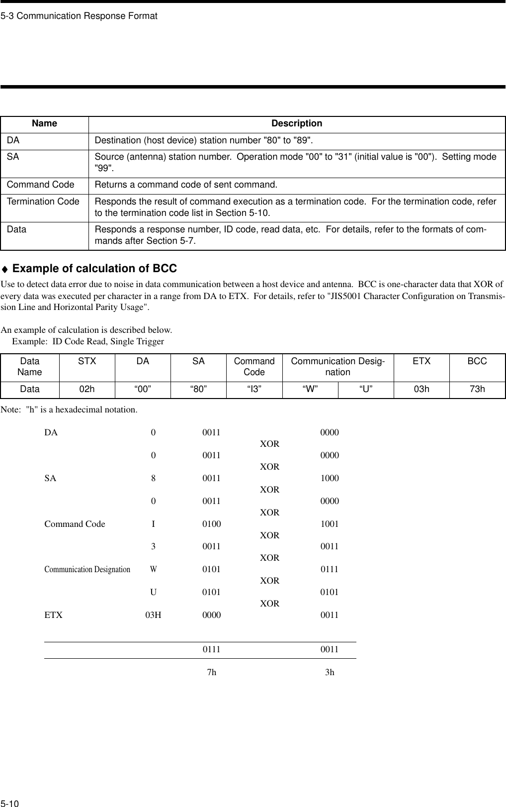
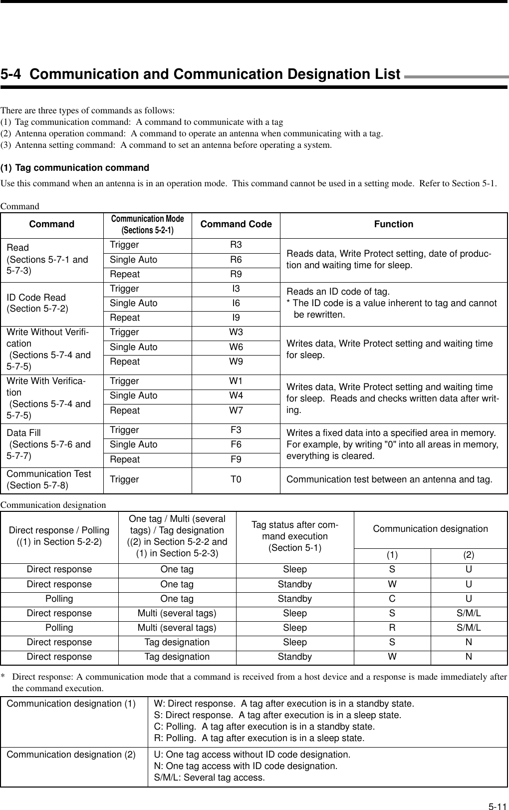
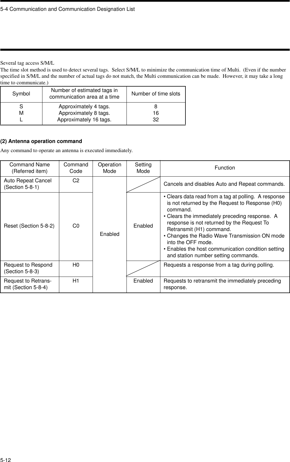
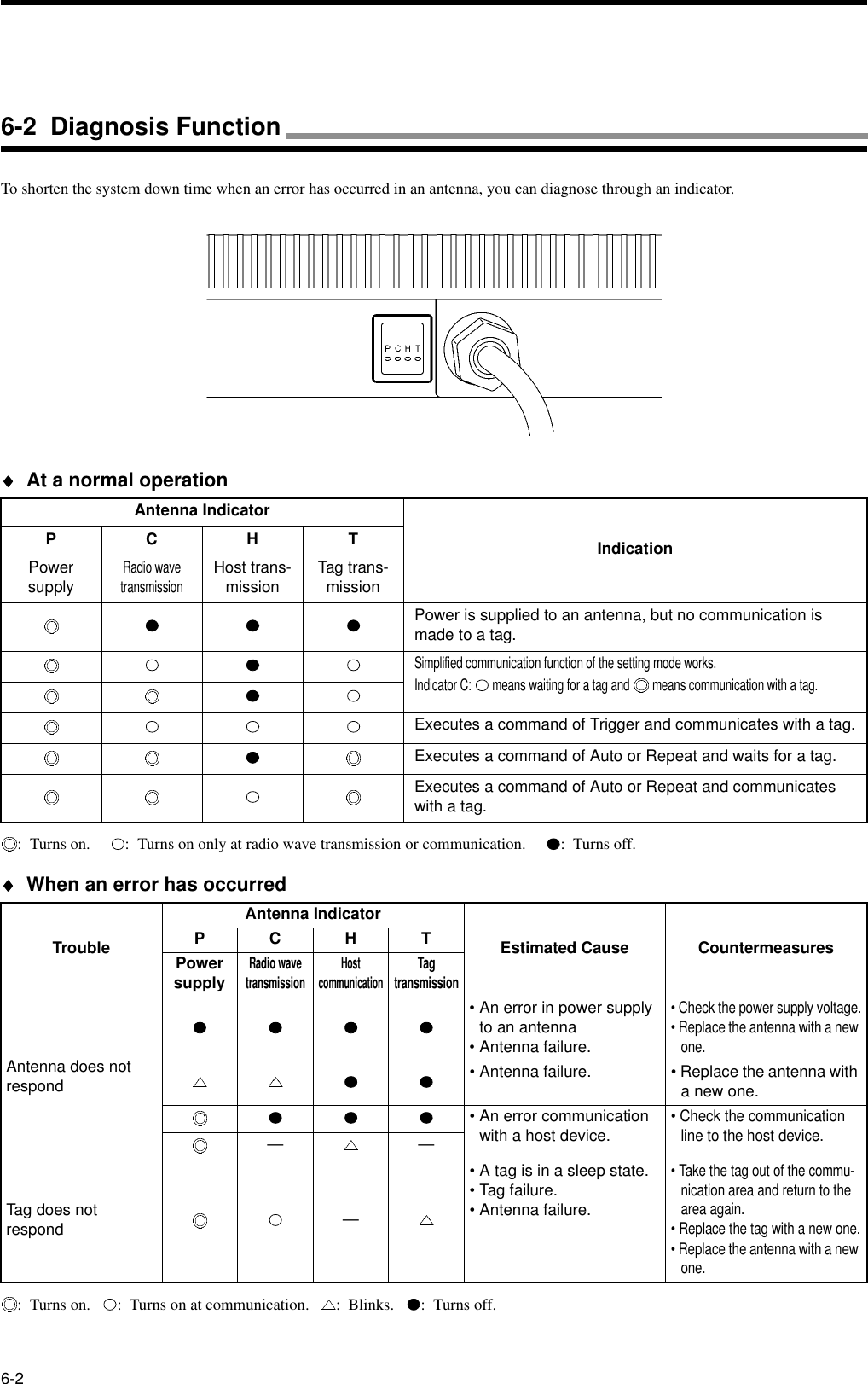
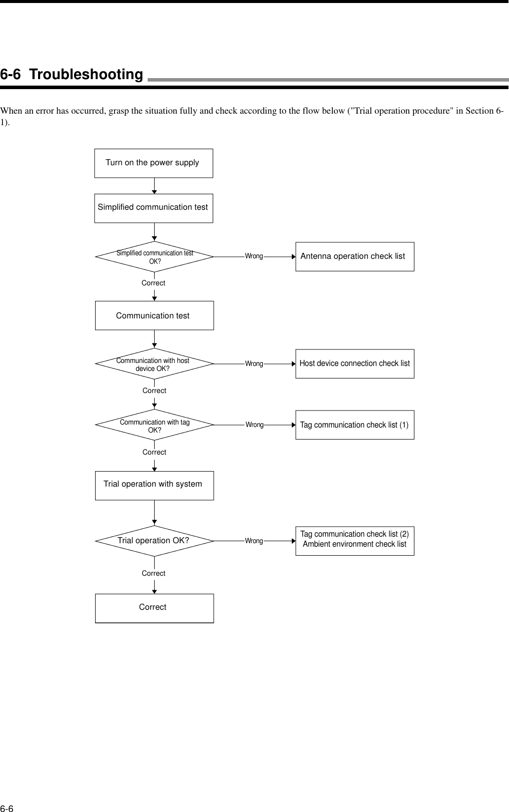
Omron 6CYCIDV6900101 Read / Write Antenna User Manual for Reader Writer Antenna
Omron Corporation Read / Write Antenna Users Manual for Reader Writer Antenna
UserManual.wiki
>
Omron
>
6CYCIDV6900101 User Manual
Users Manual for Reader Writer Antenna
Navigation menu
Upload a User Manual
Namespaces
Wiki Guide
HTML
PDF
Info
Views
User Manual
Discussion / Help
Navigation
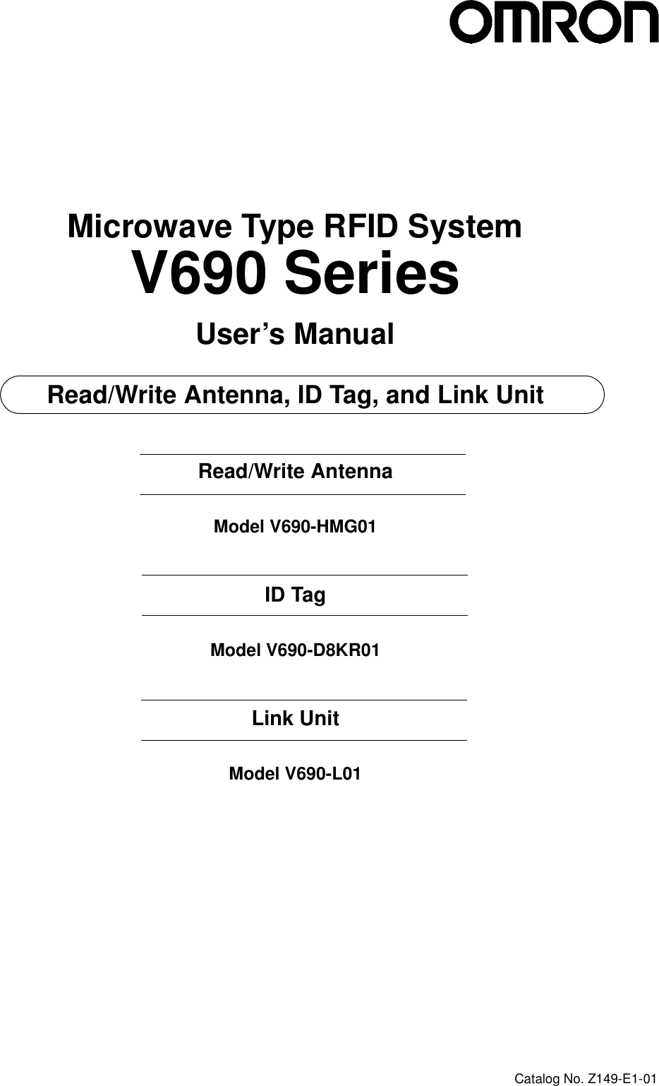

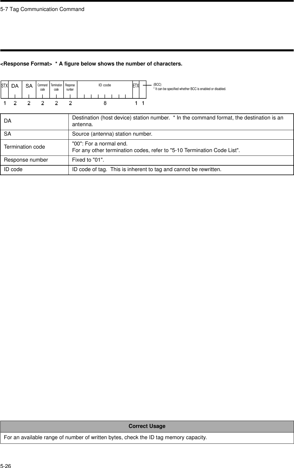
![2-2 ID Tag Model V690-D8KR012-52-2-4 Battery Life CharacteristicThe ID tag contains a battery. The charts below show the relation between the ID tag battery life, number of communication bytes and ambient temperature. The battery life means the time until the battery voltage alarm has been given.2-2-5 Battery Voltage Alarm FunctionWhen the voltage of ID tag battery becomes low, "7B" is returned to the termination code when a tag communication command (Read or Write) is executed.Correct UsageAfter the termination code 7B was generated, the ID tag can be used for approximately one month in a normal situation. However, we recommend you to replace the tag with a new one immediately.87654320102468Communication data and battery life (at the ambient temperature 25°C)Battery life(Year)Communication data kbyte (100 times/day)Conditions• Write (single trigger without verification)•One tag• The tag is in a sleep mode after a command is executed.Example of command[STX]0080W3SUAA0000 0100[Written data] [ETX]Ambient temperature and tag battery life (256 bytes x 100 times/day)Battery life(Year)Ambient temperature](https://usermanual.wiki/Omron/6CYCIDV6900101/User-Guide-226341-Page-20.png)
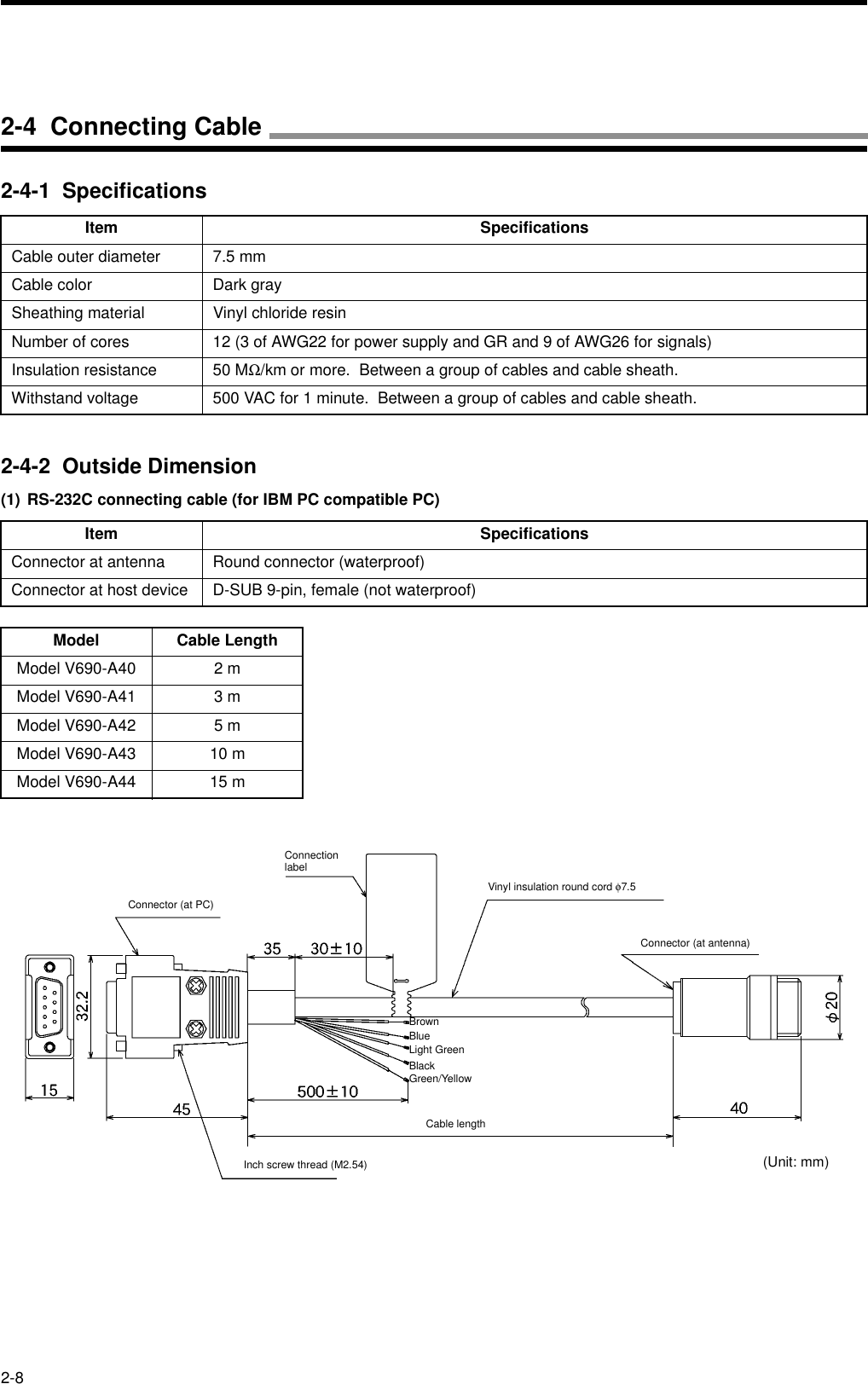
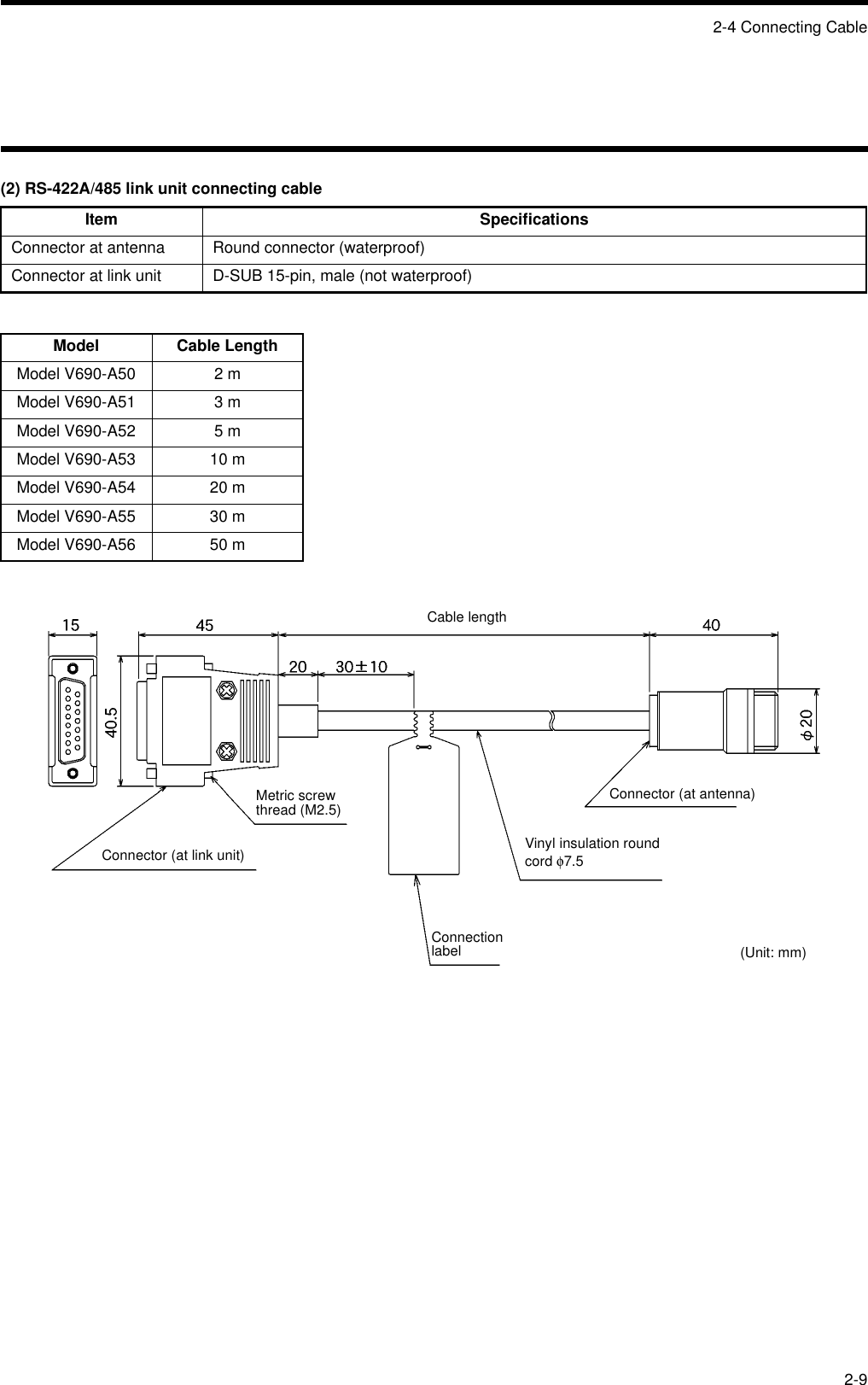
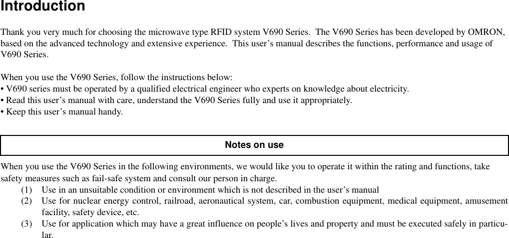
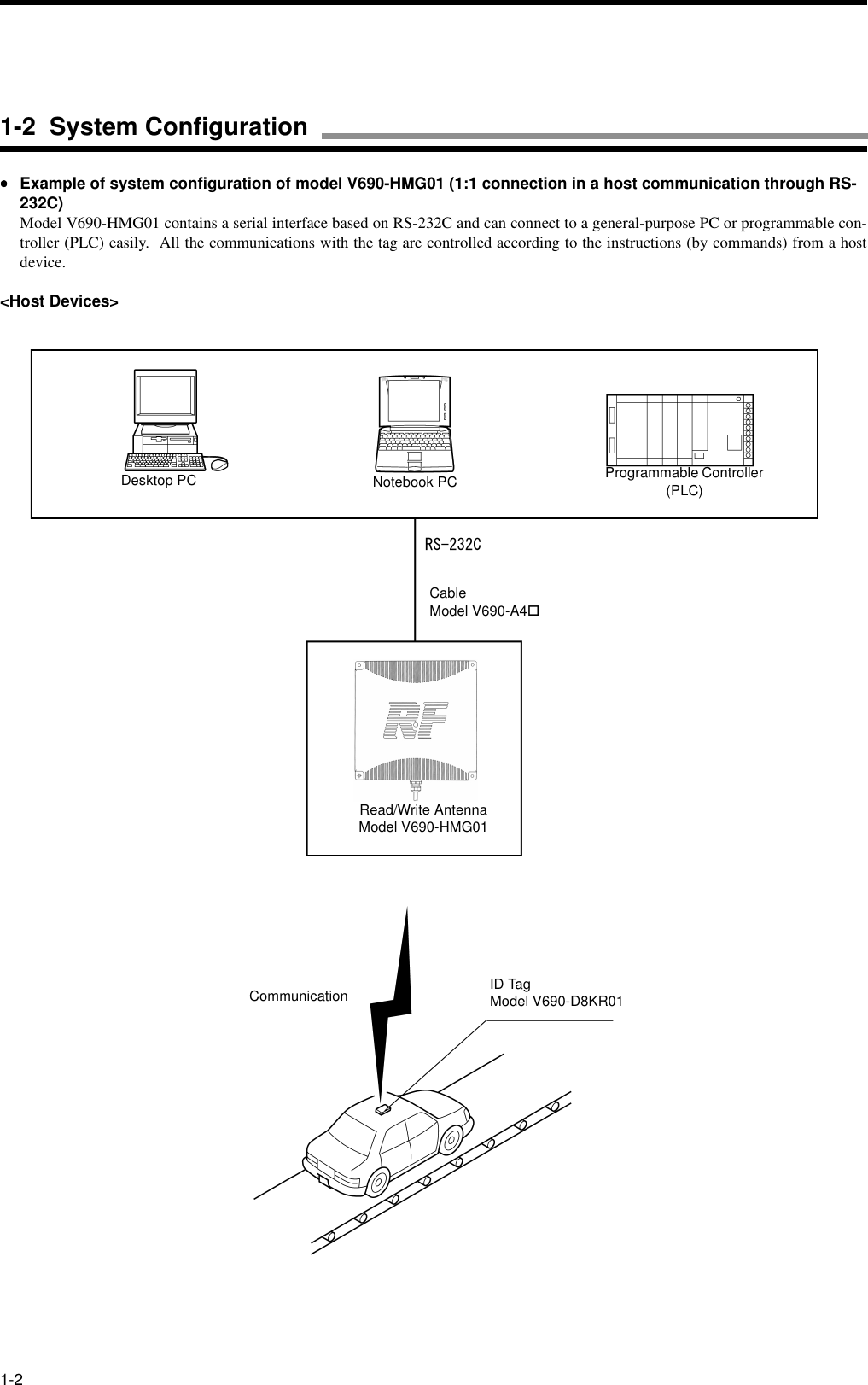
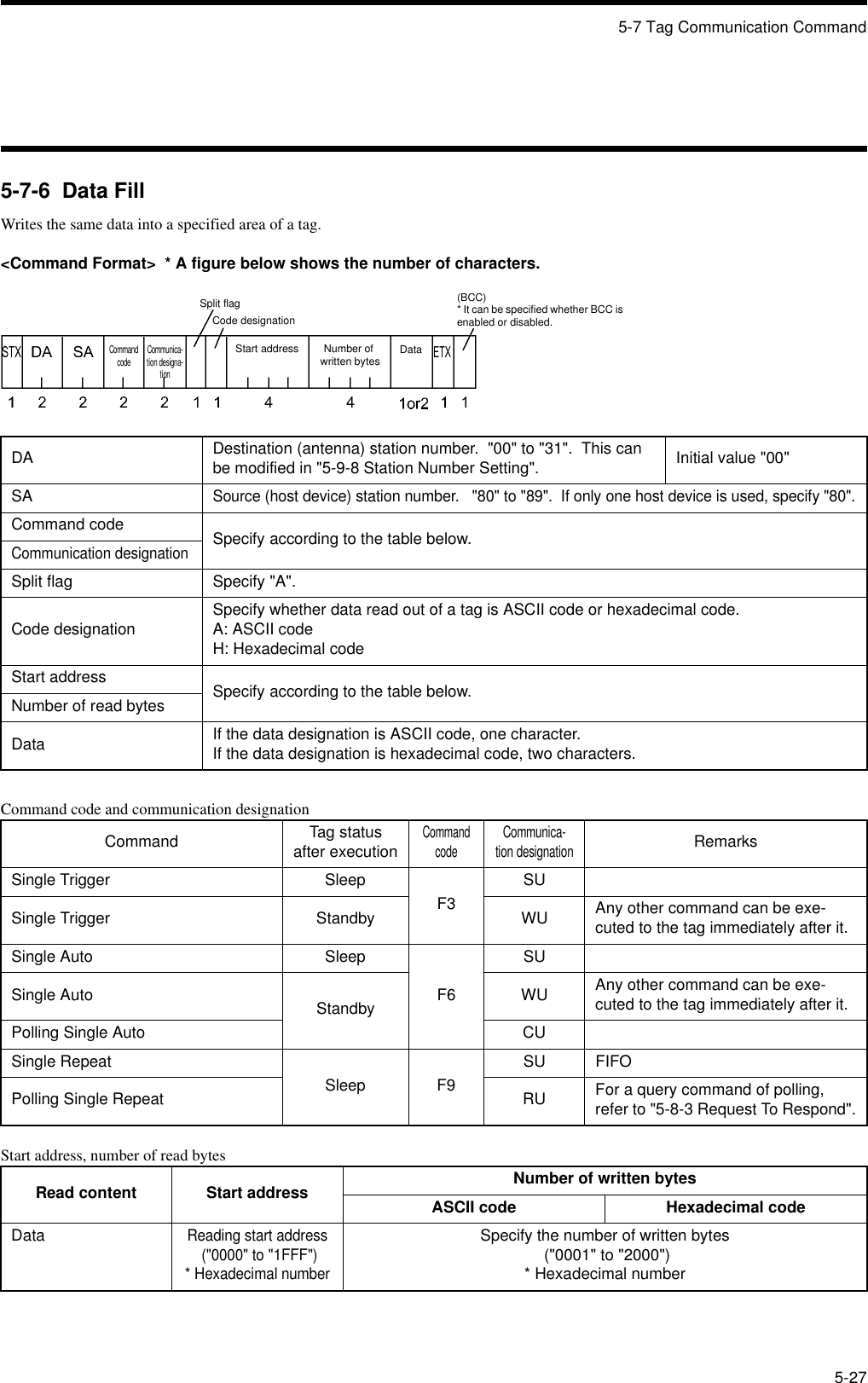
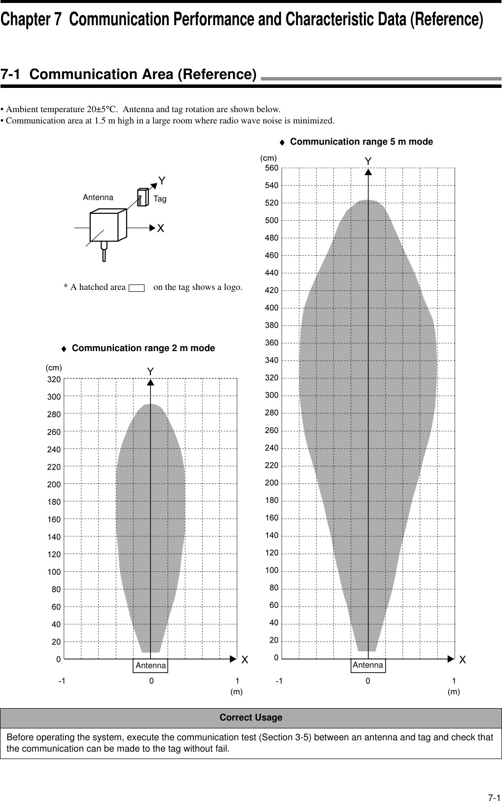
![2-10Item SpecificationsFrequency 2450 MHz band (microwave, 2434.25 - 2465.75 MHz)Type of radio station Specified low-power radio station - radio equipment for mobile object identification (RCR STD-29 Version 3.0)* A user is not required to apply a license for radio station.Transmission output at modulation 5 mW for 2 m mode and 10 mW for 5 m mode.Polarized wave Circularly polarized waveCommunication range 2 m mode/5 m mode switched by a host command. (Section 3-2)2 m mode: 0.2 to 2.0 m (Reference value)5 m mode: 0.2 to 5.0 m (Reference value)* Conditions for reference value• Ambient temperature 20±5°C• Place the tag at a suitable rotating position so that the logo "omron" can become upright.(Refer to the figure below.)• On a medial axis of antenna placed at 1.5 m high in a large room where radio wave noise is minimized.Transmission speed 600 kbpsCommunication error check CRC 16 bits are used in two ways. (CRC: Cyclic Redundancy Check)Correct Usage• The communication range varies depending on the installation site environment. This is because a metal material and the ground reflect a radio wave, and water and human body absorb it. Locate an antenna and tag in the communica-tion range and check the radio wave environment in advance.• The Read/Write antenna model V690-HMG01 has a communication test command to check the radio wave environ-ment at a working site. (Refer to Section 3-5.)[Tag Rotating angle: 0 degrees]Antenna Tag* A hatched area on the tag shows a logo.2-5 Communication Performance](https://usermanual.wiki/Omron/6CYCIDV6900101/User-Guide-226341-Page-25.png)
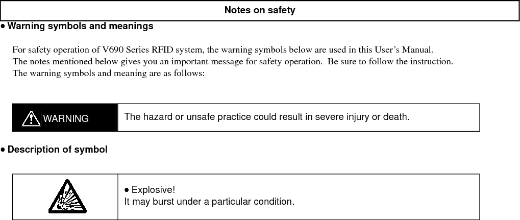
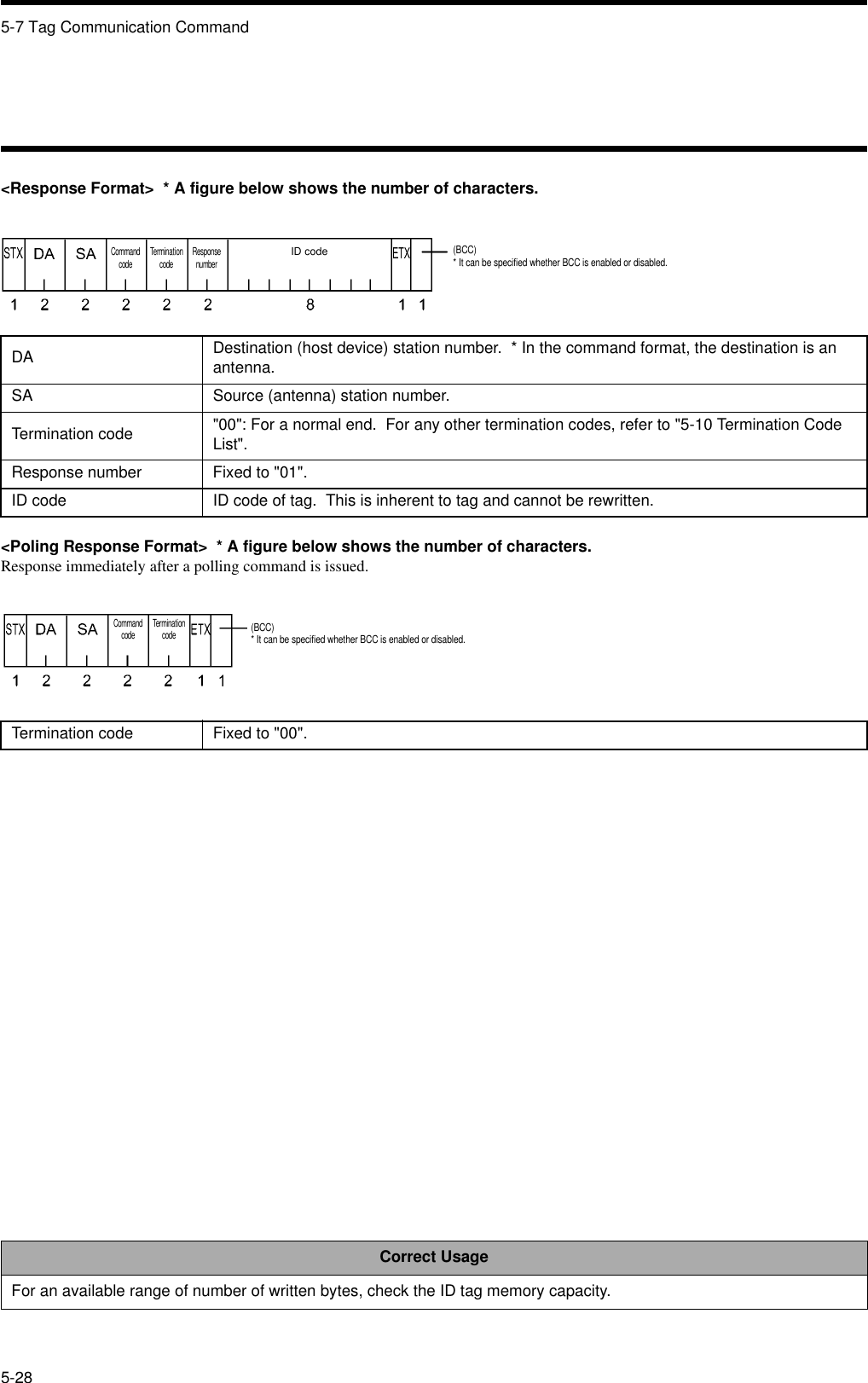
![3-5Execute the communication test to check a radio wave environment at a working site.Data (256 bytes) is communicated 256 times between the antenna and tag and the communication status is output. A total of 128 kbytes of data is communicated in two ways. So, it takes a few seconds to execute this test. The communication is not retried. Refer to Section 5-7-8.(1) Create a communication program at a host device.(2) Enable the operation mode. (Disconnect the terminals "+P" and "-P" from each other. Refer to Section 5-1.)(3) Turn on the power supply.(4) Put the tag in front of the antenna.(5) Send a communication test command (Section 5-7-8). If the antenna is 00, the command is [STX]0080T0SU[ETX].(6) If the antenna responds to the host device, the communication between the host device and antenna has been made successfully.(7) In the response [STX]8000T0000256 [ETX], a radio wave environment value is between 0000 and 0256. If the value isclose to 0000, the communication to the tag is stable.Example of response from antenna:* Radio wave environment is good.[STX] 8 0 0 0 T 0 0 0 0 2 5 6 0 0 0 0 [ETX]Number of Radio wavecommunications environment value* Radio wave environment is poor or no tag is in communication area.[STX] 8 0 0 0 T 0 0 0 0 2 5 6 0 2 5 6 [ETX]Number of Radio wavecommunications environment valueCorrect UsageWe recommend you to set the radio wave environment value to 50 or less.3-5 Communication Test](https://usermanual.wiki/Omron/6CYCIDV6900101/User-Guide-226341-Page-31.png)
![5-14You can specify a type of code used to transmit data to be read or written between a host device and Read/Write antenna.ASCII code designation and hexadecimal code designation are available.♦♦♦♦ASCII code (JIS 8 unit code) designation "A"1 byte of data of tag is transmitted directly as ASCII code or JIS 8 unit code. Transmitted one character is equal to a 1 byte of data ina tag. Character data can be read/written directly.Do not use any control code, such as [SOH] and [CR], in transmission data. Otherwise, a command error occurs.<Example 1 of writing>When "OMRON" is specified in 5 bytes of memory beginning with 10h (hexadecimal number) as writing data, data is written into tag memory as shown below.CommandResponse<Example 1 of reading>In this data shown here, when 5 bytes of memory beginning with 10h (hexadecimal number) is read out, the read data is "OMRON".CommandResponse<Example 2 of writing>When "1234" is specified in 4 bytes of memory beginning with 10h (hexadecimal number) as writing data, data is written into tag mem-ory as shown below.CommandResponseSTX DA SA Command codeCommunication designationSplit flag Code designation Start address Number of written bytes Written data ETX00 80 W1 SU A A 0010 0005 OMRONSTX DA SA Command code Termination code Response number ID code ETX80 00 W1 00 01 ∗∗∗∗∗∗∗∗STX DA SA Command codeCommunication designationSplit flag Code designation Start address Number of read bytes ETX00 80 R3 SU A A 0010 0005STX DA SA Command codeTermination code Response numberID code Split flagCode designationStart addressNumber of read bytesNumber of read dataETX80 00 R3 00 01 ******** A A 0010 0005 OMRONSTX DA SA Command codeCommunication designationSplit flag Code designation Start address Number of written bytes Written data ETX00 80 W1 SU A A 0010 0004 1234STX DA SA Command code Termination code Response number ID code ETX80 00 W1 00 01 ∗∗∗∗∗∗∗∗5-5 Data Code DesignationASCII code designationASCII code designationTag MemoryAddress Tag MemoryAddressTag MemoryAddress](https://usermanual.wiki/Omron/6CYCIDV6900101/User-Guide-226341-Page-70.png)
![7-8• The maximum communication range can be achieved when the antenna face and tag face are in parallel with each other. If theantenna and/or tag are inclined, the communication range becomes small. Install the tag paying attention to the tag angle.• For the tag rotating angle 0 degrees and 90 degrees, deterioration characteristic of communication range depending on the tag angleis shown below.• Because of antenna position in the tag, communication range deterioration varies depending on the installation angle (whether "+" or"-").••••Horizontal installation angle of tag(1) Tag rotating angle 0 degreesθθθθH (°°°°)Deterioration of communication range2 m mode 5 m mode+60 -54% -55%+45 -38% -40%+30 -23% -17%+15 -12% -8%00%0%-15 0% -1%-30 -4% -7%-45 -11% -13%-60 -26% -25%Tag rotating angle 0 degrees Tag rotating angle 90 degreesAntennaTagAntennaTagUpward[Top View]Antenna Model V690-HMG01 Tag Model V690-D8KR01* A hatched area on the tag shows a logo.7-7 Influence of Tag Installation Angle (Reference)](https://usermanual.wiki/Omron/6CYCIDV6900101/User-Guide-226341-Page-116.png)
![7-7 Influence of Tag Installation Angle (Reference)7-9(2) Tag rotating angle 90 degrees••••Vertical installation angle of tag(1) Tag rotating angle 0 degrees(2) Tag rotating angle 90 degreesθθθθH (°°°°)Deterioration of communication range2 m mode 5 m mode+60 -40% -40%+45 -23% -24%+30 -14% -11%+15 -6% -3%00%0%-15 -11% -10%-30 -26% -23%-45 -31% -35%-60 -34% -37%θθθθv (°°°°)Deterioration of communication range2 m mode 5 m mode+60 -41% -36%+45 -26% -18%+30 -10% -2%+15 0% 0%00%0%-15 -16% -13%-30 -23% -21%-45 -30% -28%-60 -42% -39%θθθθH (°°°°)Deterioration of communication range2 m mode 5 m mode+60 -60% -67%+45 -43% -50%+30 -26% -27%+15 -12% -14%00%0%-15 0% -3%-30 -2% -6%-45 -13% -14%-60 -24% -27%Antenna Model V690-HMG01 Tag Model V690-D8KR01[Side View]](https://usermanual.wiki/Omron/6CYCIDV6900101/User-Guide-226341-Page-117.png)
![Appendix-4Note 1: The code 01011100 (column 5, row 12) is " \ " in the ASCII character.b8~b5 0000 10010010 0011 0100 0101 0110 0111 1000 1001 1010 1011 1100 1101 1110 1111b4~b1 0 1 2 3 4 5 6 7 8 9 1011121314150000 0 NUL TC7(DLE)(SP)0@P`pUndefined―タミ0001 1TC1(SOH)DC1!1AQaq 。ア チ ム0010 2 TC2(STX) DC2”2BRbr 「イツメ0011 3 TC3(ETX) DC3#3CScs 」ウ テ モ0100 4 TC4(EOT) DC4$4DTd t 、エ ト ヤ0101 5TC5(NEQ)TC8(NAK) % 5 E U e u .オナユ0110 6 TC6(ACK)TC9(SYN)&6FVf v ヲカニヨ0111 7 BELTC10(ETB)’7GWgw ァキヌラ1000 8 FE0(BS) CAN ( 8 H X h x ィクネリ1001 9 FE1(HT) EM ) 9 I Y i y ゥケノル1010 10 FE2(LF) SUB * : J Z j z ェコハレ1011 11 FE3(VT) ESC + ; K [ k { ォサヒロ1100 12 FE4(FF) IS4(FS) , < L ¥l| ャシフワ1101 13 FE5(CR) IS3(GS) - = M ] m } ュスヘン1110 14 S0 IS2(RS) . > N ^ n ¯ ョセホ゛1111 15 S1 IS1(US) / ? O _ oDELッソマ゜UndefinedUndefinedUndefinedUndefinedUndefinedAppendix 2 JIS8 Unit Code List (ASCII Code List)High orderdigitLow order digit ColumnRow](https://usermanual.wiki/Omron/6CYCIDV6900101/User-Guide-226341-Page-122.png)