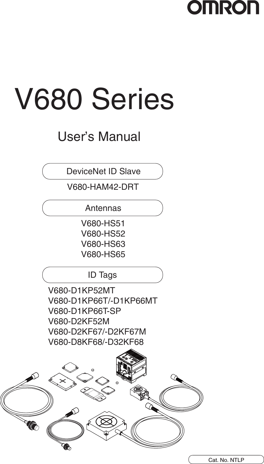
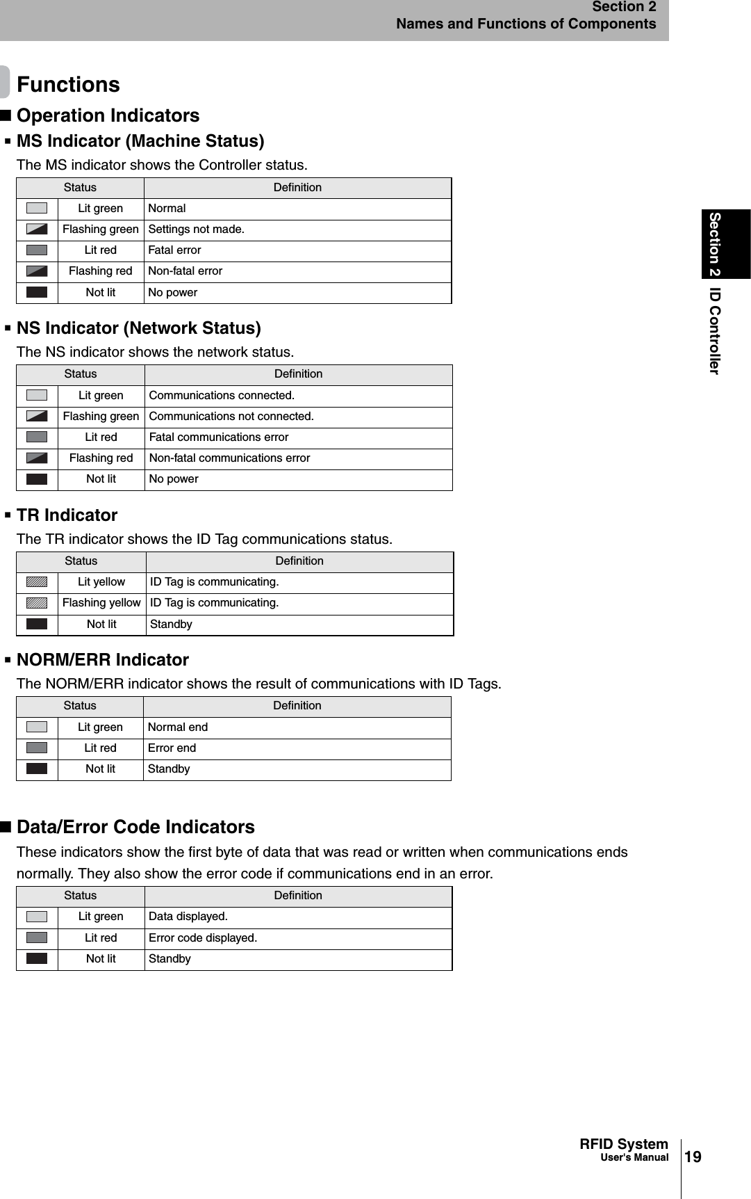
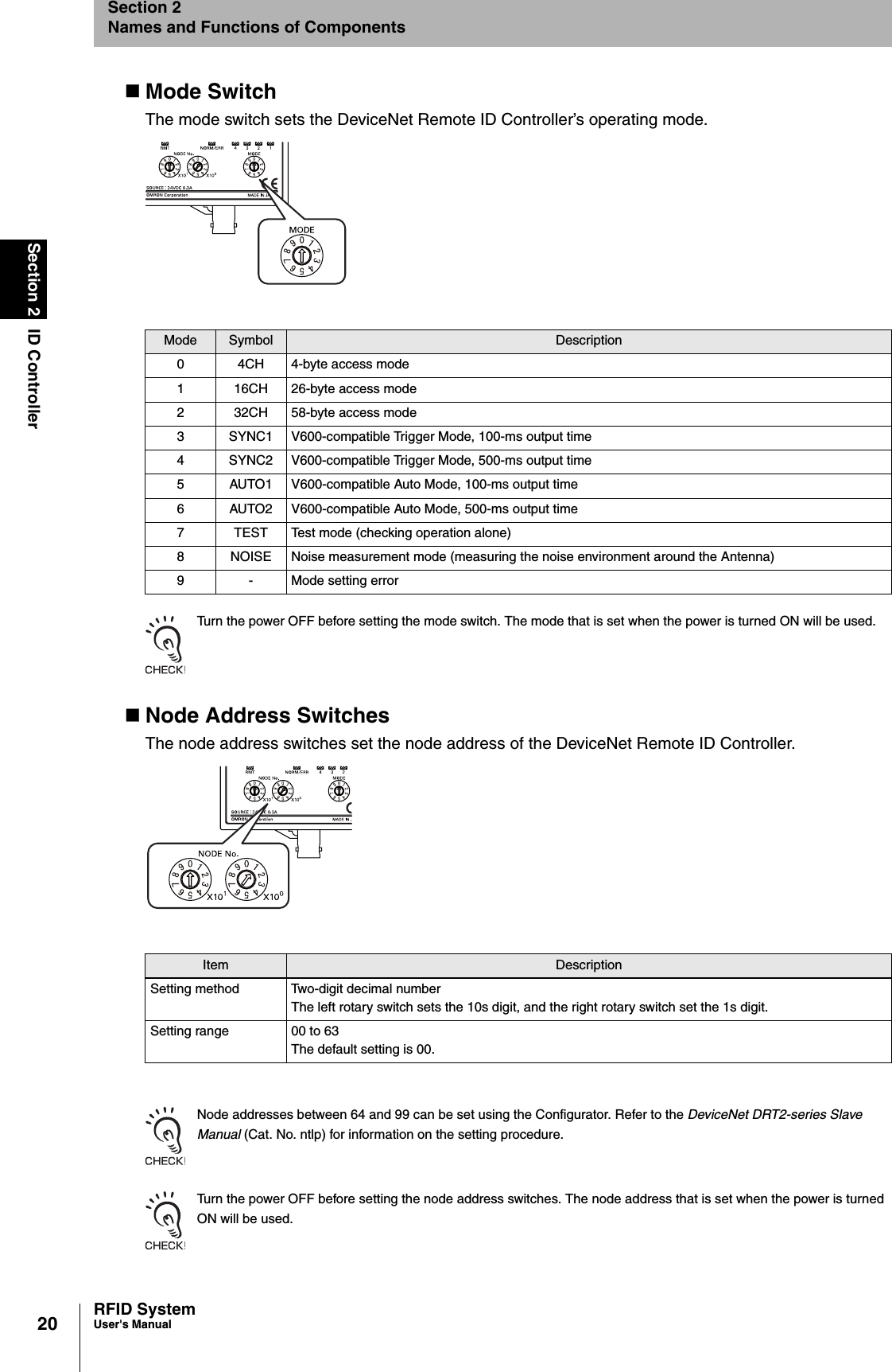
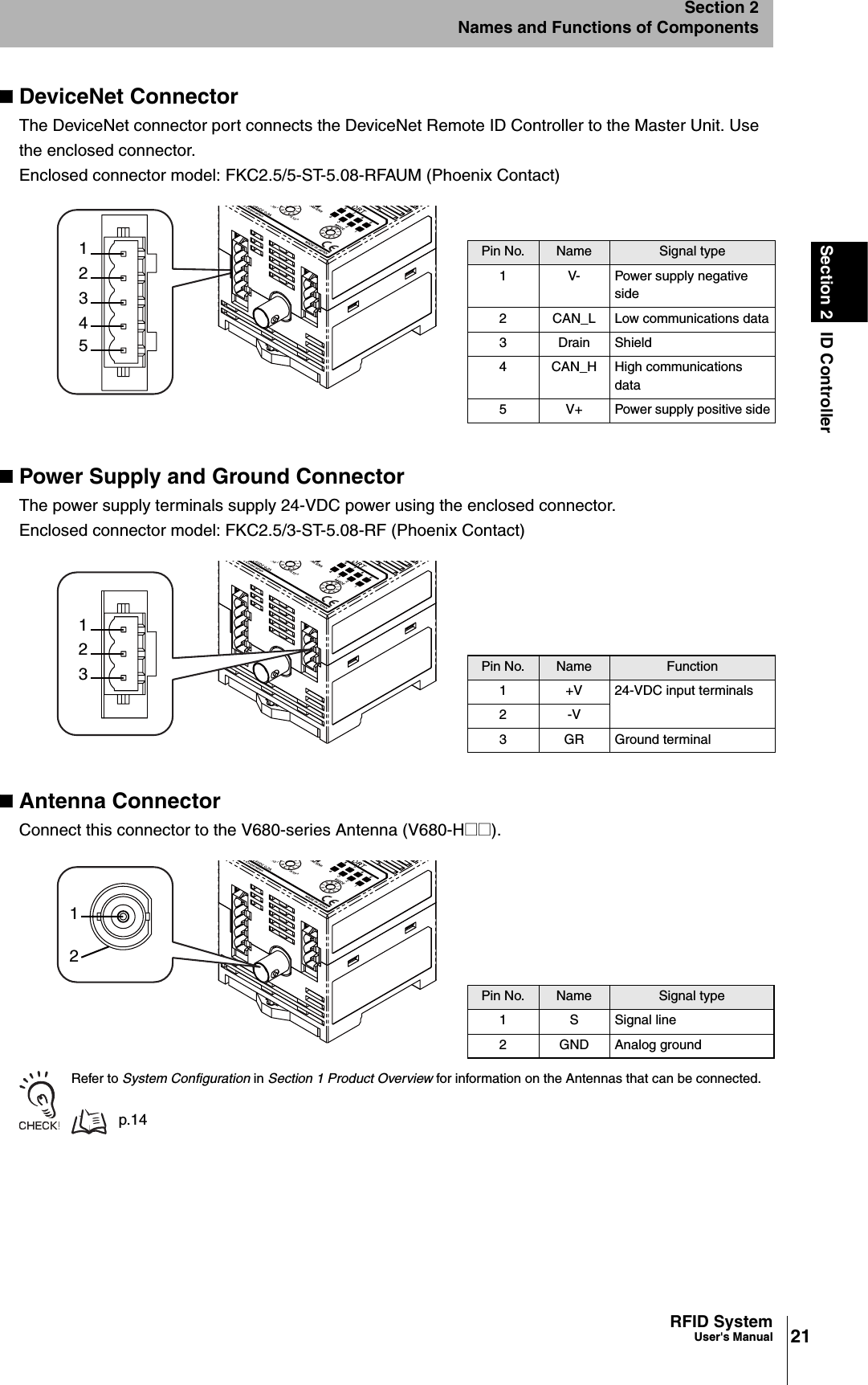
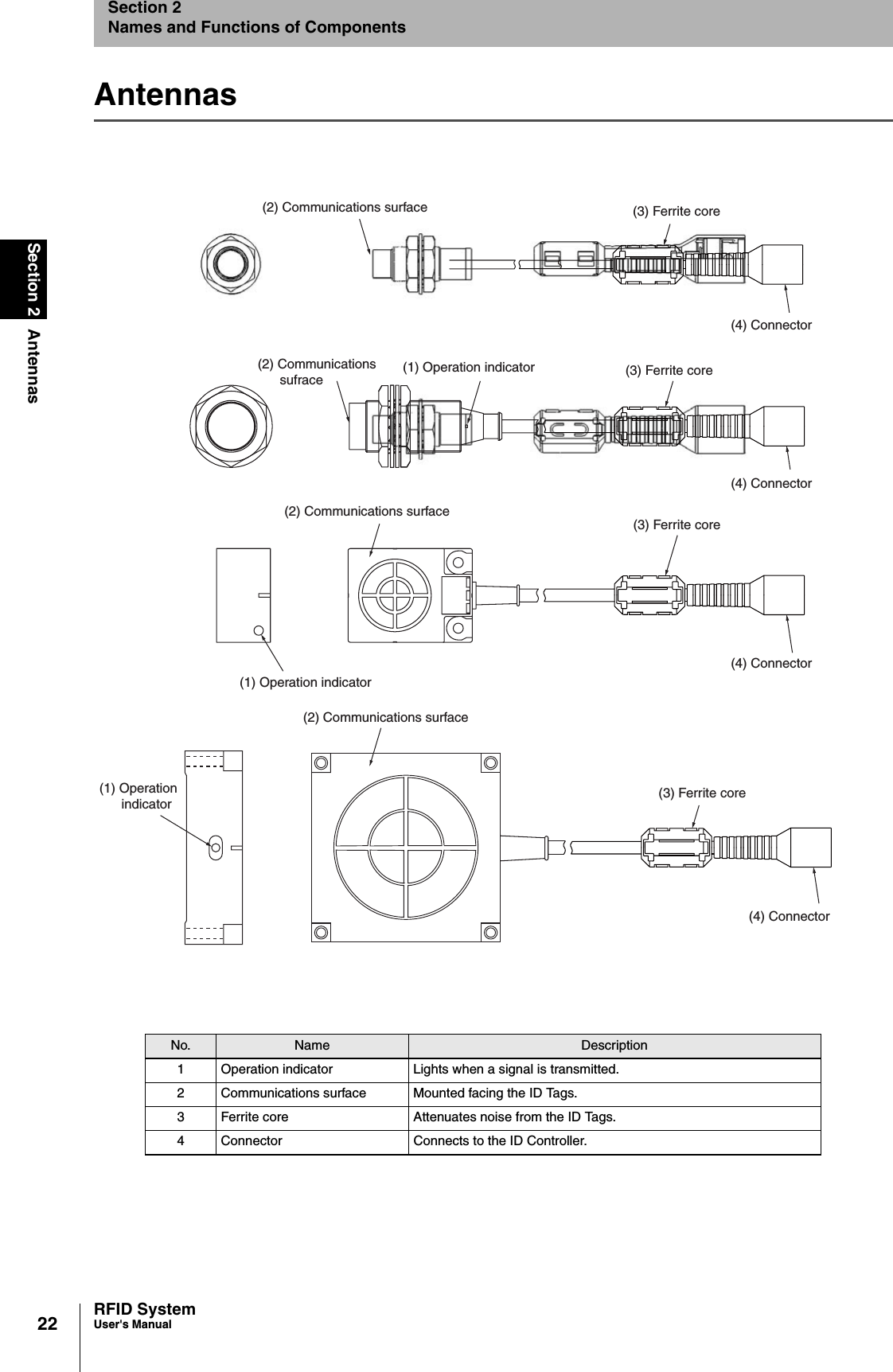
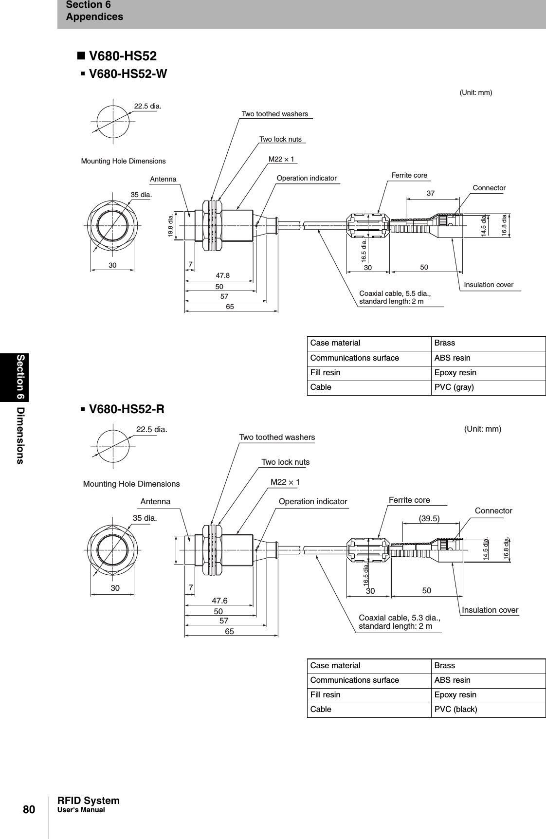
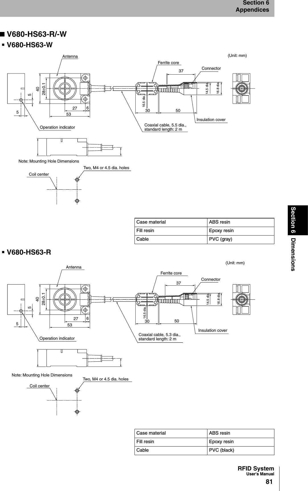
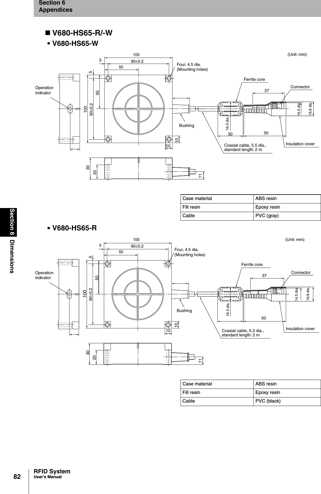
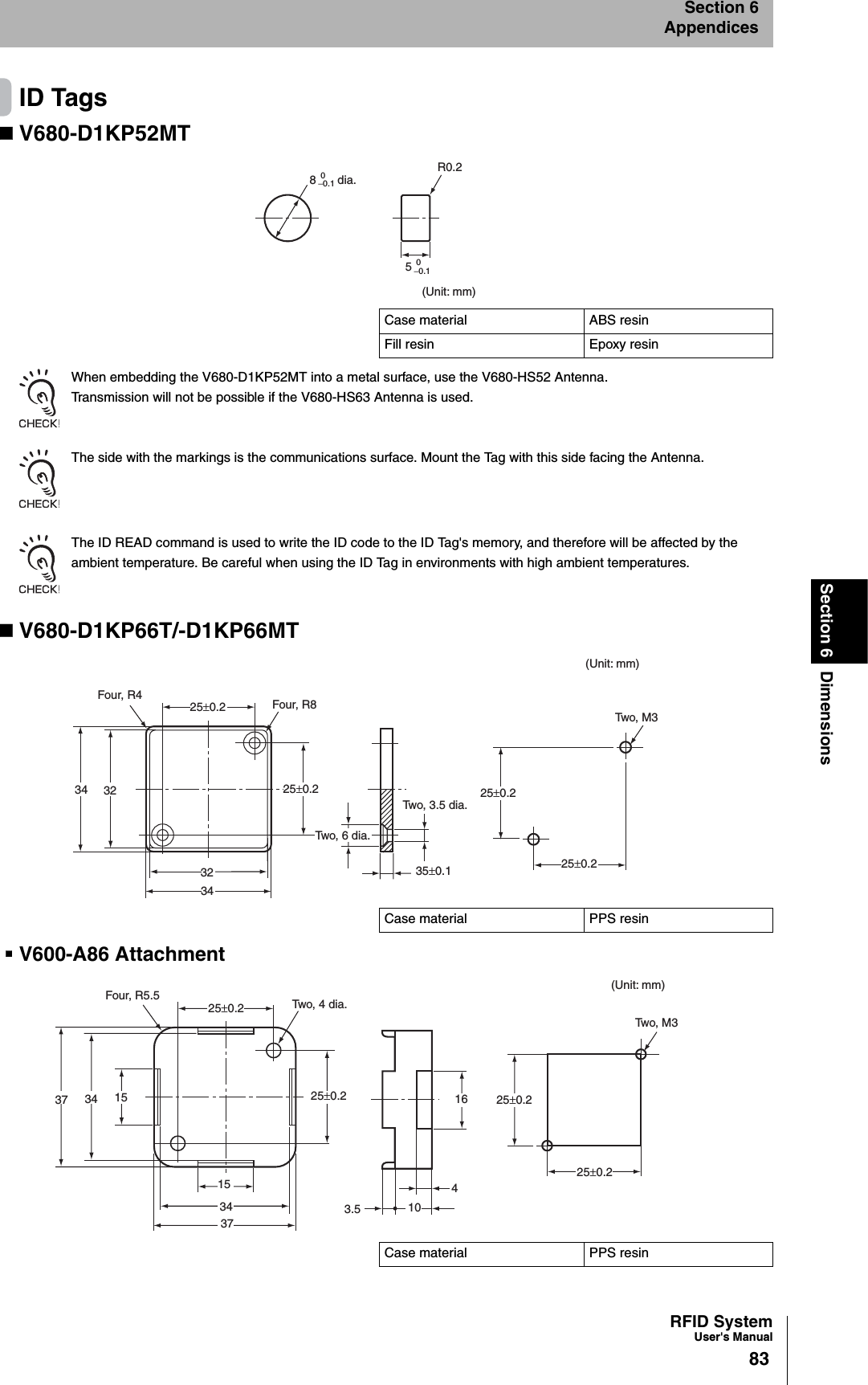
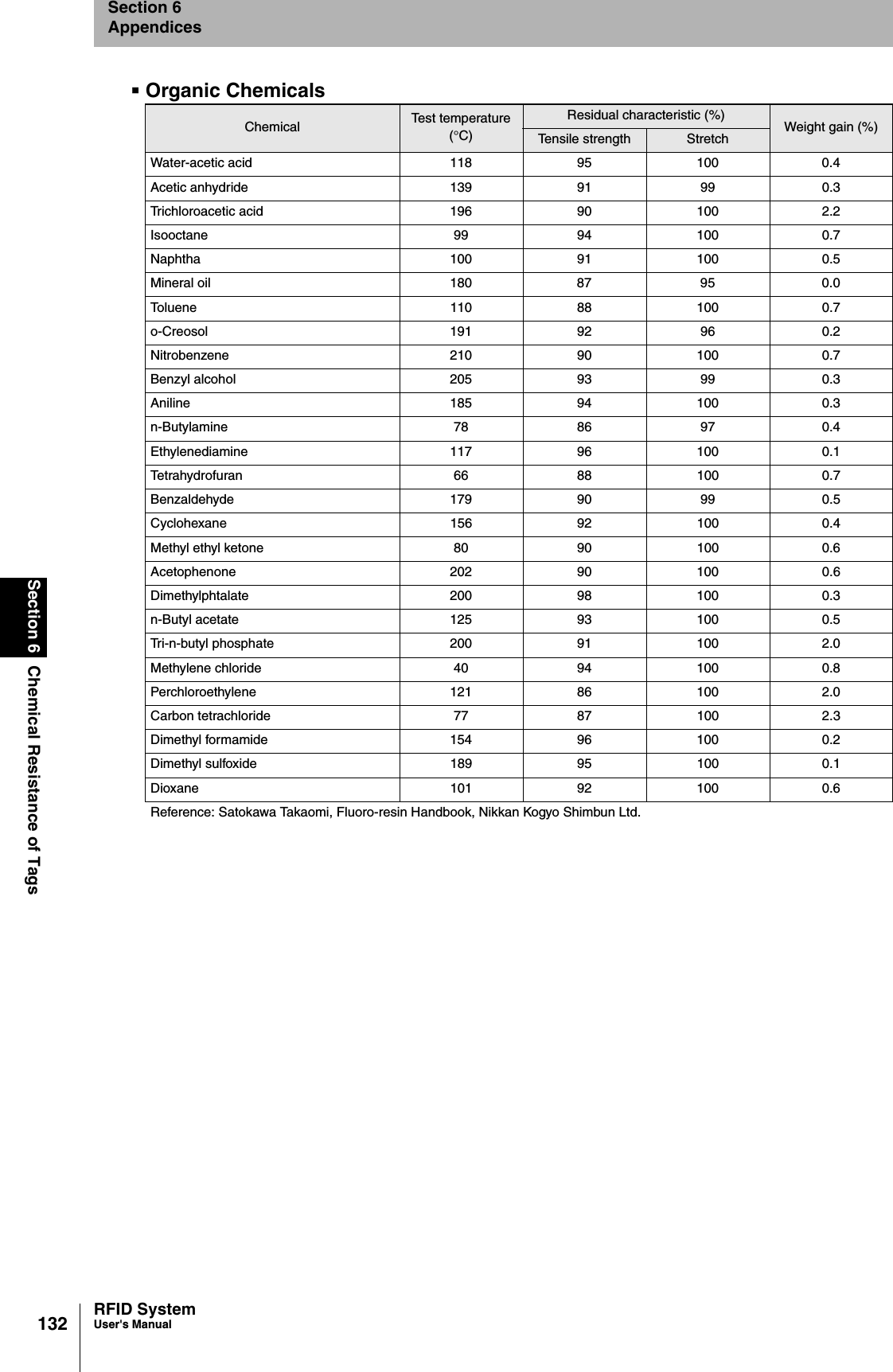
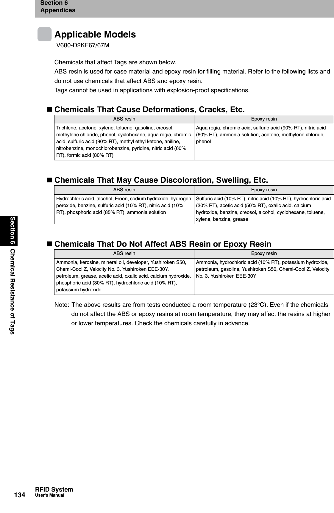
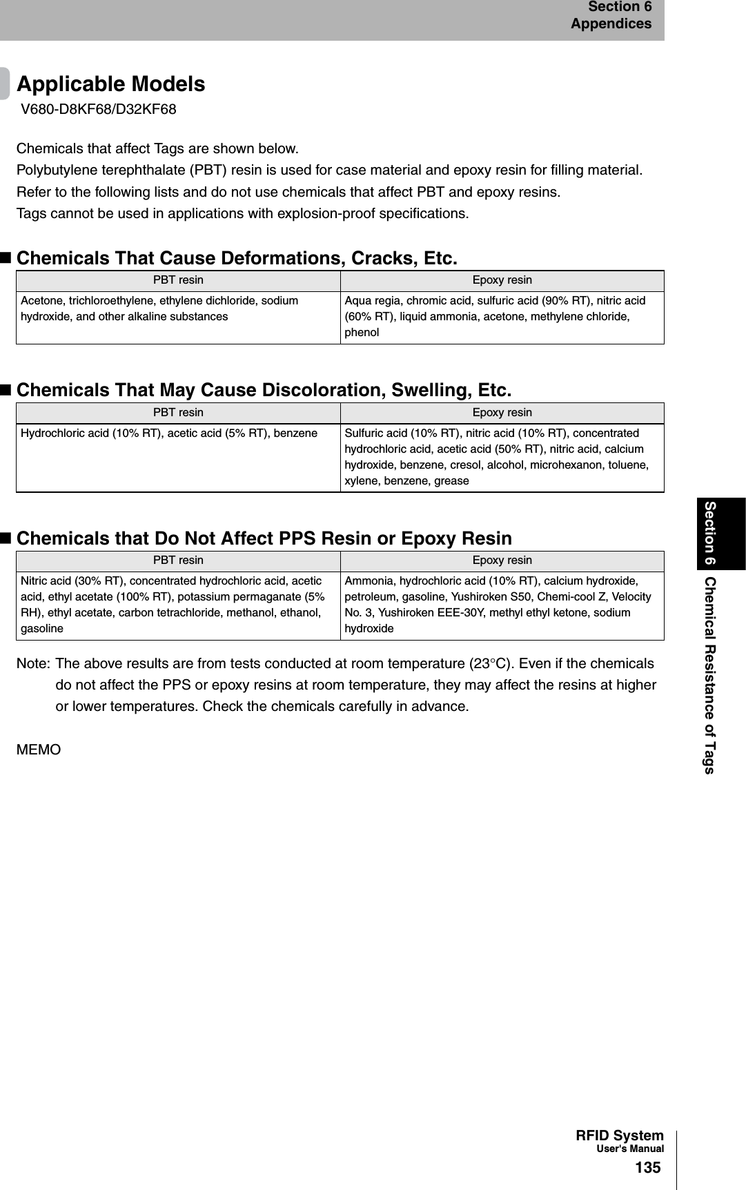
Omron 6CYSIDV6800108 RFID Device User Manual
Omron Corporation RFID Device Users Manual
UserManual.wiki
>
Omron
>
6CYSIDV6800108 User Manual
>
User Manual
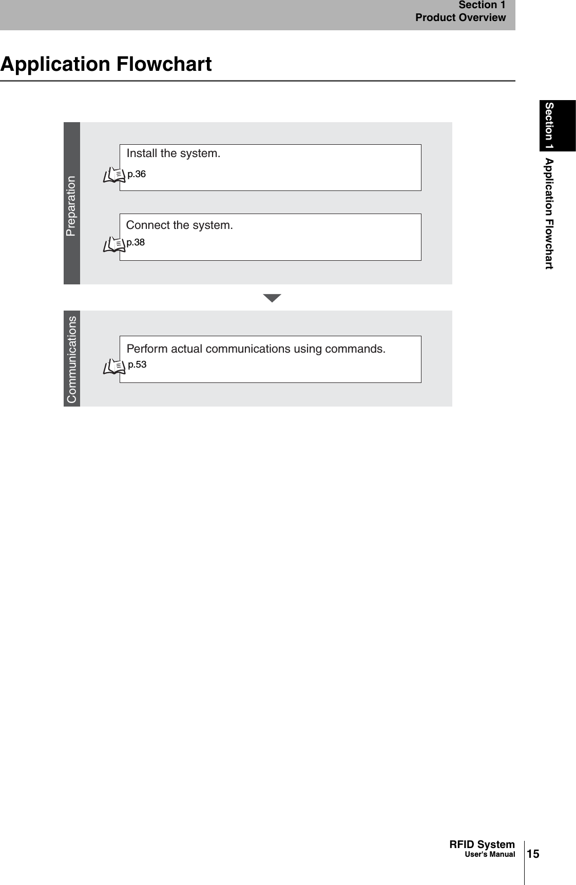
Contents
1.
User Manual
2.
05 User Manual_1
3.
05 User Manual_2
User Manual
Navigation menu
Upload a User Manual
Namespaces
Wiki Guide
HTML
PDF
Info
Views
User Manual
Discussion / Help
Navigation