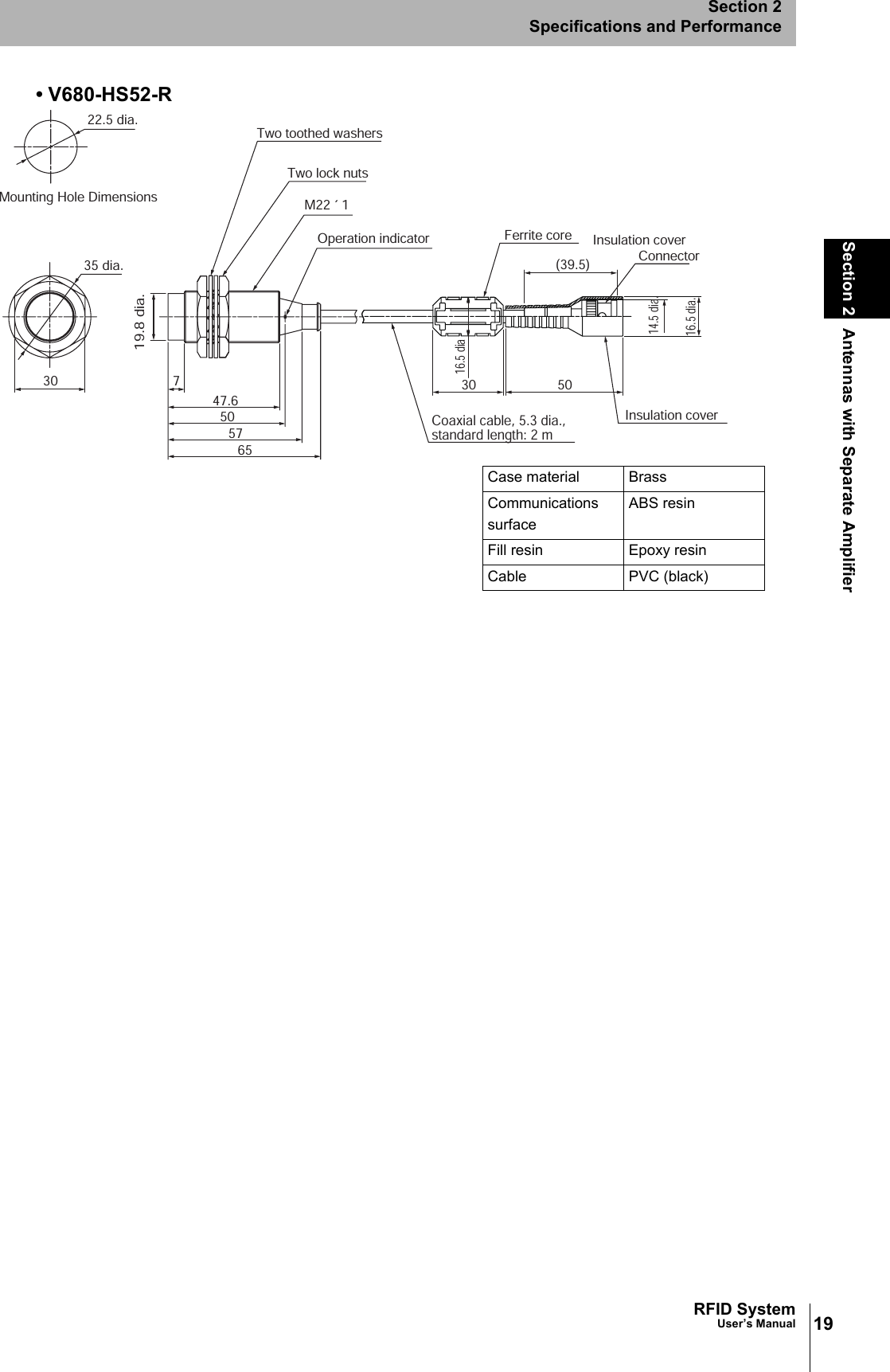
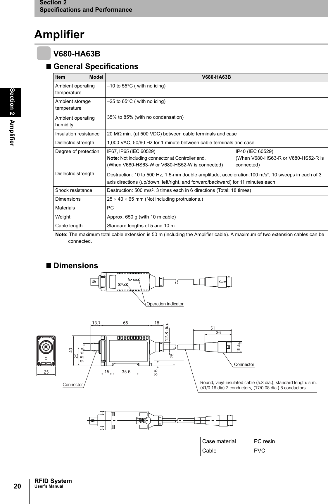
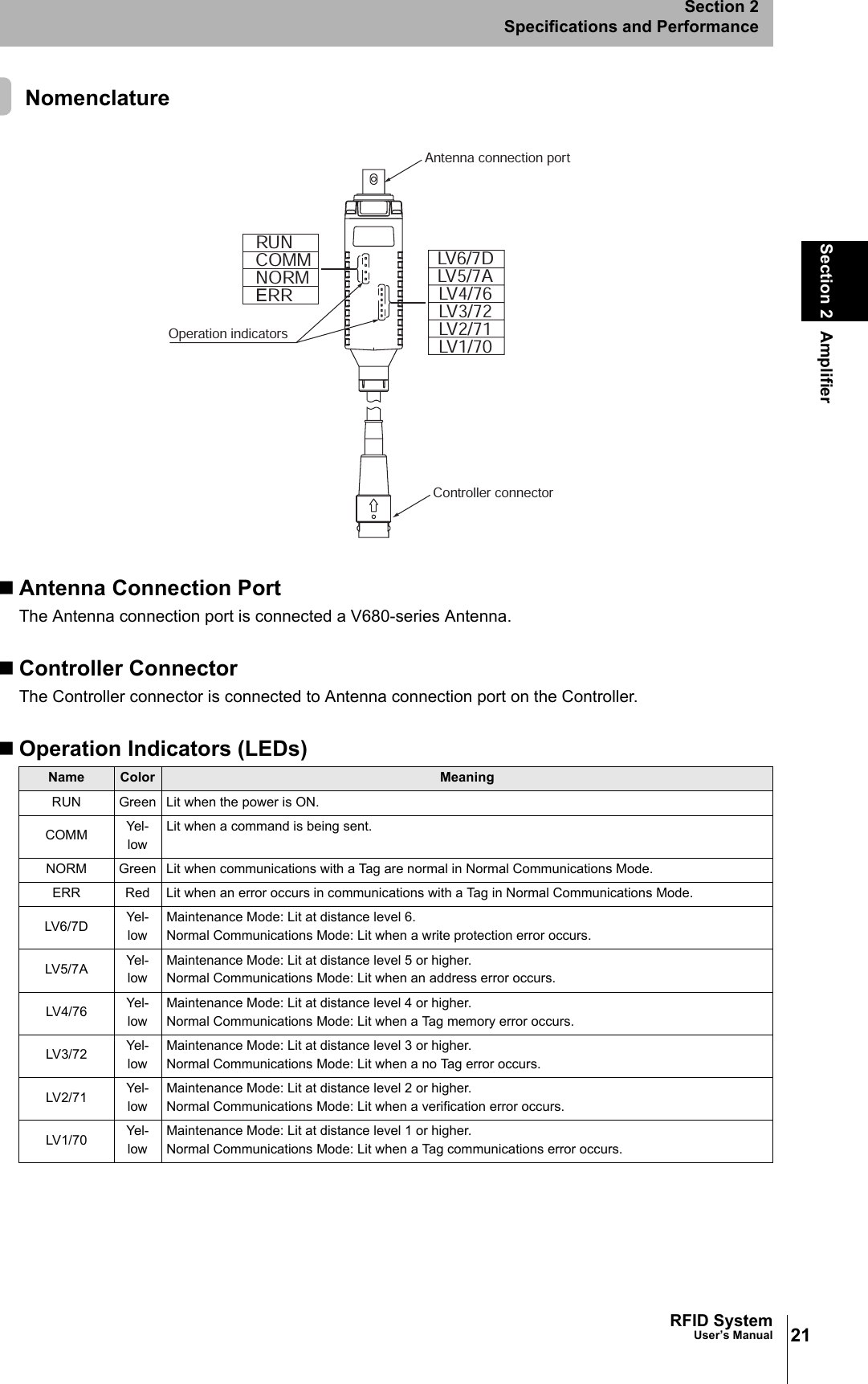
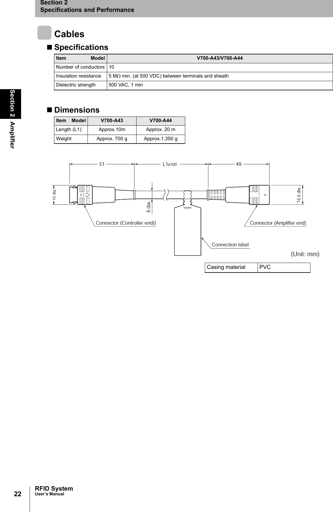
Omron 6CYSIDV6800306 RFID system User Manual user

Omron Corporation RFID system user

Manual

RFID SystemV680 SeriesUser's ManualCat. No.: Z248-E1-01Amplifier and AntennasV680-HA63BV680-HS52V680-HS63 ID TagsV680-D2KF52V680-D2KF67V680-D2KF67M
IntroductionThank you for purchasing a V680-series RFID System. This manual describes the functions, performance, and application methods needed for optimum use of the V680-series RFID System.Please observe the following items when using the RFID System.• Allow the RFID System to be installed and operated only by qualified specialist with a sufficientknowledge of electrical systems.• Read and understand this manual before attempting to use the RFID System and use the RFID Sys-tem correctly.• Keep this manual in a safe and accessible location so that it is available for reference when required.
Introduction Section 1 Section 2 Section 3 Section 4 Section 5IntroductionSection 1Section 2Section 3Section 4Section 5READ AND UNDERSTAND THIS DOCUMENTProduct OverviewSpecifications and PerformanceCommunications SpecificationsInstallationChemical ResistanceRFID SystemV680-HA63B AmplifierV680-HS52 AntennaV680-HS63 AntennaV680-D2KF52 ID TagV680-D2KF67 ID TagV680-D2KF67M ID TagUser's Manual
2IntroductionRFID SystemUser's ManualIntroductionREAD AND UNDERSTAND THIS DOCUMENTPlease read and understand this document before using the products. Please consult your OMRON representative if you have any questions or comments.WARRANTYOMRON’s exclusive warranty is that the products are free from defects in materials and workmanship for a period of one year (or other period if specified)from date of sale by OMRON.OMRON MAKES NO WARRANTY OR REPRESENTATION, EXPRESS OR IMPLIED, REGARDING NON-INFRINGEMENT, MERCHANTABILITY, OR FIT-NESS FOR PARTICULAR PURPOSE OF THE PRODUCTS. ANY BUYER OR USER ACKNOWLEDGES THAT THE BUYER OR USER ALONE HAS DETERMINED THAT THE PRODUCTS WILL SUITABLY MEET THE REQUIREMENTS OF THEIR INTENDED USE. OMRON DISCLAIMS ALL OTHER WARRANTIES, EXPRESS OR IMPLIED.LIMITATIONS OF LIABILITYOMRON SHALL NOT BE RESPONSIBLE FOR SPECIAL, INDIRECT, OR CONSEQUENTIAL DAMAGES, LOSS OF PROFITS OR COMMERCIAL LOSS IN ANY WAY CONNECTED WITH THE PRODUCTS, WHETHER SUCH CLAIM IS BASED ON CONTRACT, WARRANTY, NEGLIGENCE, OR STRICT LIABIL-ITY.In no event shall responsibility of OMRON for any act exceed the individual price of the product on which liability is asserted.IN NO EVENT SHALL OMRON BE RESPONSIBLE FOR WARRANTY, REPAIR, OR OTHER CLAIMS REGARDING THE PRODUCTS UNLESS OMRON’S ANALYSIS CONFIRMS THAT THE PRODUCTS WERE PROPERLY HANDLED, STORED, INSTALLED, AND MAINTAINED AND NOT SUBJECT TO CON-TAMINATION, ABUSE, MISUSE, OR INAPPROPRIATE MODIFICATION OR REPAIR.SUITABILITY FOR USETHE PRODUCTS CONTAINED IN THIS DOCUMENT ARE NOT SAFETY RATED. THEY ARE NOT DESIGNED OR RATED FOR ENSURING SAFETY OF PERSONS, AND SHOULD NOT BE RELIED UPON AS A SAFETY COMPONENT OR PROTECTIVE DEVICE FOR SUCH PURPOSES. Please refer to separate catalogs for OMRON's safety rated products.OMRON shall not be responsible for conformity with any standards, codes, or regulations that apply to the combination of products in the customer’s applica-tion or use of the product.At the customer’s request, OMRON will provide applicable third party certification documents identifying ratings and limitations of use that apply to the prod-ucts. This information by itself is not sufficient for a complete determination of the suitability of the products in combination with the end product, machine, system, or other application or use.The following are some examples of applications for which particular attention must be given. This is not intended to be an exhaustive list of all possible uses of the products, nor is it intended to imply that the uses listed may be suitable for the products:• Outdoor use, uses involving potential chemical contamination or electrical interference, or conditions or uses not described in this document.• Nuclear energy control systems, combustion systems, railroad systems, aviation systems, medical equipment, amusement machines, vehicles, safety equipment, and installations subject to separate industry or government regulations.• Systems, machines, and equipment that could present a risk to life or property.Please know and observe all prohibitions of use applicable to the products.NEVER USE THE PRODUCTS FOR AN APPLICATION INVOLVING SERIOUS RISK TO LIFE OR PROPERTY WITHOUT ENSURING THAT THE SYSTEM AS A WHOLE HAS BEEN DESIGNED TO ADDRESS THE RISKS, AND THAT THE OMRON PRODUCT IS PROPERLY RATED AND INSTALLED FOR THE INTENDED USE WITHIN THE OVERALL EQUIPMENT OR SYSTEM.PERFORMANCE DATAPerformance data given in this document is provided as a guide for the user in determining suitability and does not constitute a warranty. It may represent the result of OMRON’s test conditions, and the users must correlate it to actual application requirements. Actual performance is subject to the OMRON Warranty and Limitations of Liability.CHANGE IN SPECIFICATIONSProduct specifications and accessories may be changed at any time based on improvements and other reasons.It is our practice to change model numbers when published ratings or features are changed, or when significant construction changes are made. However, some specifications of the product may be changed without any notice. When in doubt, special model numbers may be assigned to fix or establish key spec-ifications for your application on your request. Please consult with your OMRON representative at any time to confirm actual specifications of purchased products.DIMENSIONS AND WEIGHTSDimensions and weights are nominal and are not to be used for manufacturing purposes, even when tolerances are shown.ERRORS AND OMISSIONSThe information in this document has been carefully checked and is believed to be accurate; however, no responsibility is assumed for clerical, typographical, or proofreading errors, or omissions.PROGRAMMABLE PRODUCTSOMRON shall not be responsible for the user’s programming of a programmable product, or any consequence thereof.COPYRIGHT AND COPY PERMISSIONThis document shall not be copied for sales or promotions without permission. This document is protected by copyright and is intended solely for use in con-junction with the product. Please notify us before copying or reproducing this document in any manner, for any other purpose. If copying or transmitting this document to another, please copy or transmit it in its entirety.
3RFID SystemUser's ManualIntroductionIntroductionAlert Symbols for Safe UseThe following symbols are used in this manual to indicate precautions that must be observed to ensure safeuse of the V680-HS63, V680-HS52, and V680-HA63B. The precautions provided here contain important safety information. Be sure to observe these precautions.The following signal words are used in this manual.Meanings of Alert SymbolsWarningThe V680-HS63, V680-HS52, and V680-HA63 conform to the following overseas regulations and standards.1. FCC Rules (Federal Communications Commission)This product complies with Part 15 Subpart C of the FCC Rules.FCC ID: E4E6CYSIDV6800306FCC NOTICEThis device complies with part 15 of the FCC Rules. Operation is subject to the following two conditions:(1) This device may not cause harmful interference.(2) This device must accept any interference received, including interference that may cause undesired operation.FCC WARNINGChanges or modifications not expressly approved by the party responsible for compliance could void the user's author-ity to operate the equipment.Properly shielded ground cables and connectors must be used for connection to host computer and/or peripherals inorder to meet FCC emission limits.Ferrite cores (TDK Type ZCAT1730-0730A or its equivalent) must be attached to the cables connecting the power sup-ply and ground to suppress RF interference.Safety PrecautionsIndicates a potentially hazardous situation which, if not avoided, will result in minor or mod-erate injury, or may result in serious injury or death. Additionally, there may be significant property damage.Indicates general prohibitions for which there is no specific symbol.These Products are not designed to be used either directly or indirectly in applications that detect human presence for the purpose of maintaining safety. Do not use these Products as a sensing means for protect-ing human lives.Regulations and StandardsWARNINGWARNING
4IntroductionRFID SystemUser's ManualIntroduction2. EC Declaration of ConformityHereby, OMRON Corporation declares that this RFID System, Antenna V680-HS52, V680-HS63, and Amplifier V680-HA63B.Amplifier and Antenna are in compliance with essential requirements and other relevant provisions of Directive1995/5/EC, and satisfy tests for the appropriate requirements of the following relevant standards.Radio: EN 300 330-2V1.1.1 (06-2001)EN 300 330-1V1.3.1 (06-2001)EMC: EN 301 489-3V1.4.1 (08-2002)EN 301 489-1V1.4.1 (08-2002)Safety: EN 61010-1: 2001 (2nd Edition)Countries of intended use:Austria, Belgium, Denmark, Estonia, Finland, France, Germany, Greece, Iceland, Ireland, Italy, Liechtenstein, Luxem-bourg, Netherlands, Norway, Portugal, Romania, Spain, Sweden, Switzerland, United KingdomChanges or modifications not expressly approved by the party responsible for compliance could void the user's author-ity to operate the equipment.Properly shielded ground cables and connectors must be used for connection to host computer and/or peripherals inorder to meet FCC emission limits.Ferrite cores (TDK Type ZCAT1730-0730A or its equivalent) must be attached to the cables connecting the power sup-ply and ground to suppress RF interference.3. Japan Radio LawEquipment using high frequencies: Inductive Reading/Writing Communications EquipmentConforming standards: Inductive Reading/Writing Communications Equipment; Standard: ARIB STD-T82English Hereby, Omron, declares that the RFID System, V680-HS52 Series, V680-HS63 Series, and V680-HA63B Series are in compliance with the essentialrequirements and other relevant provisions of Directive 1999/5/EC.Finnish Omron vakuuttaa täten että RFID Säännös, V680-HS52 Series, V680-HS63 Series, V680-HA63B Series tyyppinen laite on direktiivin 1999/5/EY oleellis-ten vaatimusten ja sitä koskevien direktiivin muiden ehtojen mukainen.Dutch Hierbij verklaart Omron dat het toestel de RFID Systeem, V680-HS52 ´Serie, V680-HS63 ´Serie, V680-HA63B ´Serie in overeenstemming is met deessentiële eisen en de andere relevante bepalingen van richtlijh 1999/5/EG.French Par la présente Omron déclare que la RFID Système, V680-HS52 Série, V680-HS63 Série, V680-HA63B Série sont conforme aux exigences essentielleset aux autres dispositions pertinentes de la directive 1999/5/CE.Swedish Härmed intygar Omron att den RFID System, V680-HS52 Serie, V680-HS63 Serie, V680-HA63B Serie stär l överensstämmelse med de väsentliga egen-skapskrav och övriga relevanta bestämmelser som framgår av direktiv 1999/5/EG.Danish Undertegnede Omron erklærer herved, at følgende den RFID System, V680-HS52 Serie, V680-HS63 Serie, 680-HA63B Serie overholder de væsentligekrav og øvrige relevante krav i direktiv 1999/5/EF.German Hiermit erklärt Omron, die RFID System, V670-H11 Serie, V680-HS63 Serie, V680-HA63B Serie in Übereinstimmung mit den grundlegendenAnforderungen und den anderen relevanten Vorschriften der Richtlinie 1999/5/EG befindet. (BMWi)Greek ME THN ΠAPOYSA Omron ∆HΛONEI RFID O’YO’ΓΗΜΑ, V680-HS52 O’EIPA, V680-HS63 O’EIPA, V680-HA63B O’EIPA SYMMOPF ONETAIΠPOS TIS OYSIO∆EIS AΠAITHSEIS KAI TIS ΛOIΠES SXETIKES ∆IATAΞEIS THS O∆HΓIAS 1999/5/EK.Italian Con la presente Omron dichiara che la RFID Sistema, V680-HS52Serie, V680-HS63 Serie, V680-HA63B Serie sono conforme ai requisiti essenziali edalle altre disposizioni pertinenti stabilite dalla direttiva 1999/5/CE.Spanish Por medio de la presente Omron declara que el RFID Sistema, V680-HS52 Serie, V680-HS63 Serie, V680-HA63B Serie esta conforme a los requisitosesenciales y cualesquiera otras disposiciones aplicables o exigibles de la Directiva 1999/5/CE.Portuguese Omron declara que a RFID Sistema, V680-HS52 Série, V680-HS63 Série, V680-HA63B Série ser conforme com os tequisitos essenciais e outras dis-posições da Directiva 1999/5/CE.Romanian Prin prezenta, Omron declar  c  acest V680-HS52,V680-HS63, V680-HA63 este conform cu cerin ele principale çi cu celelalte prevederi relevanate aleDirectivei 1999/5/EC.
5RFID SystemUser's ManualIntroductionIntroductionBe sure to observe the following precautions to ensure safe use of the Products.1. Do not use the Products in environments with flammable, explosive, or corrosive gasses.2. Do not attempt to disassemble, repair, or modify any Product.3. Tighten mounting screws securely.4. If any cable has a locking mechanism, make sure that it has been locked before using the cable.5. Do not allow water or pieces of wire to enter from openings in the case. Doing so may cause fire orelectric shock.6. Turn OFF the Controller power supply before mounting or removing an Antenna or Amplifier.7. If an error is detected in any Product, immediately stop operation and turn OFF the power supply. Consultwith an OMRON representative.8. Dispose of the Products as industrial waste.9. Observe all warnings and precautions given in the body of this manual.10.Make sure that there is no adverse effect of radio waves on medical equipment.The Japan Automatic Identification Systems Association (JAISA) guidelines are as follows:These Antennas for RFID devices use radio waves. They may adversely affect medical equipment,depending on where and in what applications they are used. To minimize the effects of radio waves,observe the following countermeasure for people with implanted cardiac pacemakers or other medicaldevices when using RFID devices: Do not bring the Antenna for RFID devices any closer than 22 cm to the implanted location of the car-diac pacemaker.Precautions for Safe Use
6IntroductionRFID SystemUser's ManualIntroductionAlways observe the following precautions to prevent operation failures, malfunctions, and adverse effects on performance and equipment.1. Installation EnvironmentDo not use the Products in the following locations.• Locations exposed to corrosive gases, dust, metallic powder, or salts• Locations not within the specified operating temperature range• Locations subject to rapid changes in temperature or condensation• Locations not within the specified humidity range• Locations subject to direct vibration or shock outside the specified ranges• Locations subject to spray of water, oil, or chemicals2. InstallationThe Products communicate with Tags using the 13.56-MHz frequency band. Some motors, inverters,and switching power supplies generate noise that can affect communications with the Tags and causeerrors. If such devices are located near the Tags, always test operation in advance to confirm whetherthe system will be affected.• Observe the following precautions to minimize the effects of normal noise.(1) Ground all metal objects in the vicinity of the Products to 100 Ω or less.(2) Do not use the Products near high-voltage or high-current lines.• Do not use non-waterproof Products in an environment where mist is present.• Do not expose the Products to chemicals that adversely affect the Product materials.• When mounting the Products, tighten the screws to the following torques.V680-HS63: 1.2 N⋅mV680-HS52: 40 N⋅m• If multiple Antennas are mounted near each other, communications performance may decrease dueto mutual interference. Refer to Installing Antennas on page 32 and check to make sure there is nomutual interference. • Depending on the operating environment, the case surface may become fogged, but basic perfor-mance will not be affected. 3. StorageDo not store the Products in the following locations.• Locations exposed to corrosive gases, dust, metallic powder, or salts• Locations not within the specified storage temperature range• Locations subject to rapid changes in temperature or condensation• Locations not within the specified storage humidity range • Locations subject to direct vibration or shock outside the specified ranges• Locations subject to spray of water, oil, or chemicals4. Cleaning• Do not clean the Products with paint thinner or the equivalent. Paint thinner or the equivalent will dis-solve the resin materials and case coating.Precautions for Correct Use
7RFID SystemUser's ManualIntroduction Meanings of SymbolsIntroductionMeanings of SymbolsIndicates particularly important points related to a function, including precautions and application advice.Indicates page numbers containing relevant information.
8Introduction Meanings of SymbolsRFID SystemUser's ManualIntroductionMEMO
9RFID SystemUser's ManualIntroductionIntroductionTable of ContentsSafety Precautions 3Regulations and Standards 3Precautions for Safe Use 5Precautions for Correct Use 6Meanings of Symbols 7Table of Contents 9Section 1  Product Overview 11Features 12Product Configuration 13Section 2  Specifications and Performance 15Antennas with Separate Amplifier 16Amplifier 20Tags 23Section 3  Communications Specifications 27Communications Distances 28Section 4  Installation 31Installing Antennas 32Mounting Amplifiers 33Installing Tags 37Section 5  Chemical Resistance 39Chemical Resistance of the Antennas 40Revision History 42
10 RFID SystemUser's ManualIntroductionIntroduction
Section 1 Product Overview11RFID SystemUser's ManualSection 1Product OverviewFeatures 12 Product Configuration 13
12Section 1 FeaturesRFID SystemUser’s ManualSection 1Product OverviewFeaturesThe V680-series RFID System actively supports many different types of system, such as distributed-controlsystems and many-product, small-lot production systems, with non-contact data communications usingelectromagnetic induction. Non-contact Data CommunicationsThe V680 Series uses electromagnetic induction to enable non-contact, bi-directional data communi-cations between Antennas and Tags.CRC Used for Transmission Error DetectionA bi-directional 16-bit CRC (Cyclic Redundancy Check) has been added as the error detection methodfor wire transmissions between ID Controllers and Antennas, and for wireless transmissions betweenAntennas and Tags. This method maintains superior communications reliability even where problemssuch as noise occur.Superior Environmental Resistance and High ReliabilityAntennas and Tags now have greater environmental resistance and are not affected by vibration, oil, orwater.
13RFID SystemUser’s ManualSection 1 Product ConfigurationSection 1Product OverviewProduct ConfigurationA V680-series RFID System consists of an ID Controller, one or more Amplifiers, one or two Antennas, andTags. Select the models suitable for the application. V680-HA63BV680-HS63V680-HS52V680-CA5D01Personal computer Programmable Controller (PLC)V680-D2KF67 V680-D2KF52V680-D2KF67MV680-CA5D02RS-232C RS-422 RS-485Host deviceID ControllerAmplifiersAntennas with Separate  AmplifierTags
14Section 1 Product ConfigurationRFID SystemUser’s ManualSection 1Product OverviewMEMO
Section 2 Specifications and Performance15RFID SystemUser's ManualSection 2Specifications and PerformanceAntennas with Separate Amplifier 16Amplifier 20Tags 23
16Section 2 Antennas with Separate AmplifierRFID SystemUser’s ManualSection 2Specifications and PerformanceAntennas with Separate AmplifierV680-HS63General SpecificationsDimensions• V680-HS63-WItem Model V680-HS63-W(Standard cable, waterproof connector)V680-HS63-R(Flexible cable, non-waterproof connector)Ambient operating temperature−10 to 60°C (with no icing)Ambient storage temperature−25 to 75°C (with no icing)Ambient operating humidity35% to 95% (with no condensation)Insulation resistance  20 MΩ min. (at 500 VDC) between cable terminals and caseDielectric strength 1,000 VAC, 50/60Hz for 1 min between cable terminals and caseDegree of protection  IP67G (Head)Note: The connector specifications are IP67 and IP65. IP67G (Head)Note: The connectors are not waterproof.Vibration resistance Destruction: 10 to 500 Hz, 1.5-mm double amplitude, acceleration: 100 m/s2, 10 sweeps in each of 3 axis directions (up/down, left/right, and forward/backward) for 11 minutes eachShock resistance Destruction: 500 m/s2, 3 times each in 6 directions (Total: 18 times) Dimensions 40 × 53 × 23 mmMaterial ABS resin case, epoxy resin fillerWeight Approx. 850 g (with 12.5 m cable)Cable length Standard lengths of 2 and 12.5 m(Unit: mm)2355Operation indicator4028±0.15327 611Note: Mounting Hole DimensionsCoil centerTwo, M4 or 4.5 dia. holes37503016.5 dia.Coaxial cable, 5.5 dia.,  standard length: 2 mConnectorFerrite coreInsulation cover16.5 dia.14.5 dia.Case material ABS resinFill resin Epoxy resinCable PVC (gray)
17RFID SystemUser’s ManualSection 2 Antennas with Separate AmplifierSection 2Specifications and Performance• V680-HS63-R23554028±0.15327 611(Unit: mm)Operation indicatorNote: Mounting Hole DimensionsCoil centerTwo, M4 or 4.5 dia. holes503016.5 diaCoaxial cable, 5.3 dia.,  standard length: 2 mInsulation cover(39.5) ConnectorFerrite core16.5 dia.14.5 dia.Case material ABS resinFill resin Epoxy resinCable PVC (black)
18Section 2 Antennas with Separate AmplifierRFID SystemUser’s ManualSection 2Specifications and PerformanceV680-HS52General SpecificationsDimensions• V680-HS52-WItem Model V680-HS52-W(Standard cable, waterproof connector)V680-HS52-R(Flexible cable, non-waterproof connector)Ambient operating temperature−10 to 60°C (with no icing)Ambient storage temperature−25 to 75°C (with no icing)Ambient operatinghumidity35% to 95% (with no condensation)Insulation resistance 20 MΩ min. (at 500 VDC) between connector terminals and caseDielectric strength 1,000 VAC, 50/60 Hz for 1 min between connector terminals and caseDegree of protection IP67G (Head)Note: The connector specifications are IP67 and IP65.IP67G (Head)Note: The connectors are not waterproof. Dielectric strength Destruction: 10 to 500 Hz, 1.5-mm double amplitude, acceleration: 100 m/s2, 10 sweeps in each of 3 axis directions (up/down, left/right, and forward/backward) for 8 minutes eachShock resistance Destruction: 500 m/s2, 3 times each in 6 directions (Total: 18 times)Dimensions M22 × 65 mmMaterial ABS resin, brass, and epoxy resin fillerWeight Approx. 850 g (with 12.5 m cable)Cable length Standard lengths of 2 and 12.5 m6547.6575073019.8 dia.35 dia.22.5 dia.Mounting Hole DimensionsTwo toothed washersTwo lock nutsM22 ´ 1Operation indicator37503016.5 dia.Coaxial cable, 5.5 dia.,  standard length: 2 mConnectorFerrite coreInsulation cover16.5 dia.14.5 dia.Case material BrassCommunicationssurfaceABS resinFill resin Epoxy resinCable PVC (gray)
19RFID SystemUser’s ManualSection 2 Antennas with Separate AmplifierSection 2Specifications and Performance• V680-HS52-R6547.6575073019.8 dia.35 dia.22.5 dia.Mounting Hole DimensionsTwo toothed washersTwo lock nutsM22 ´ 1Operation indicator Insulation cover503016.5 diaCoaxial cable, 5.3 dia.,  standard length: 2 mInsulation cover(39.5) ConnectorFerrite core16.5 dia.14.5 dia.Case material BrassCommunicationssurfaceABS resinFill resin Epoxy resinCable PVC (black)
20Section 2 AmplifierRFID SystemUser’s ManualSection 2Specifications and PerformanceAmplifierV680-HA63BGeneral SpecificationsDimensionsItem Model V680-HA63BAmbient operating temperature−10 to 55°C ( with no icing)Ambient storage temperature−25 to 65°C ( with no icing)Ambient operatinghumidity35% to 85% (with no condensation)Insulation resistance 20 MΩ min. (at 500 VDC) between cable terminals and caseDielectric strength 1,000 VAC, 50/60 Hz for 1 minute between cable terminals and case.Degree of protection IP67, IP65 (IEC 60529)Note: Not including connector at Controller end.(When V680-HS63-W or V680-HS52-W is connected)IP40 (IEC 60529)(When V680-HS63-R or V680-HS52-R is connected)Dielectric strength Destruction: 10 to 500 Hz, 1.5-mm double amplitude, acceleration:100 m/s2, 10 sweeps in each of 3 axis directions (up/down, left/right, and forward/backward) for 11 minutes eachShock resistance Destruction: 500 m/s2, 3 times each in 6 directions (Total: 18 times)Dimensions 25 × 40 × 65 mm (Not including protrusions.)Materials PCWeight Approx. 650 g (with 10 m cable)Cable length Standard lengths of 5 and 10 mNote: The maximum total cable extension is 50 m (including the Amplifier cable). A maximum of two extension cables can be connected.Operation indicator13.7 65 1851 3615 dia.40259.5 dia.253.512.8 dia.15 35.625Round, vinyl-insulated cable (5.8 dia.), standard length: 5 m, (41/0.16 dia) 2 conductors, (17/0.08 dia.) 8 conductorsConnectorConnectorCase material PC resinCable PVC
21RFID SystemUser’s ManualSection 2 AmplifierSection 2Specifications and Performance NomenclatureAntenna Connection PortThe Antenna connection port is connected a V680-series Antenna.Controller ConnectorThe Controller connector is connected to Antenna connection port on the Controller.Operation Indicators (LEDs)Name Color MeaningRUN Green Lit when the power is ON.COMM Yel-lowLit when a command is being sent.NORM Green Lit when communications with a Tag are normal in Normal Communications Mode.ERR Red Lit when an error occurs in communications with a Tag in Normal Communications Mode.LV6/7D Yel-lowMaintenance Mode: Lit at distance level 6.Normal Communications Mode: Lit when a write protection error occurs.LV5/7A Yel-lowMaintenance Mode: Lit at distance level 5 or higher.Normal Communications Mode: Lit when an address error occurs.LV4/76 Yel-lowMaintenance Mode: Lit at distance level 4 or higher.Normal Communications Mode: Lit when a Tag memory error occurs.LV3/72 Yel-lowMaintenance Mode: Lit at distance level 3 or higher.Normal Communications Mode: Lit when a no Tag error occurs.LV2/71 Yel-lowMaintenance Mode: Lit at distance level 2 or higher.Normal Communications Mode: Lit when a verification error occurs.LV1/70 Yel-lowMaintenance Mode: Lit at distance level 1 or higher.Normal Communications Mode: Lit when a Tag communications error occurs.Operation indicatorsRUNCOMMNORMERRLV6/7DLV5/7ALV4/76LV3/72LV2/71LV1/70Antenna connection portController connector
22Section 2 AmplifierRFID SystemUser’s ManualSection 2Specifications and PerformanceCablesSpecificationsDimensionsItem Model V700-A43/V700-A44Number of conductors 10Insulation resistance 5 MΩ min. (at 500 VDC) between terminals and sheathDielectric strength 500 VAC, 1 minItem Model V700-A43 V700-A44Length (L1) Approx.10m Approx. 20 mWeight Approx. 700 g Approx.1,350 g51 L1±1004915.5 dia.Connector (Controller end))Connection labelConnector (Amplifier end)6 dia.15 dia.(Unit: mm)Casing material PVC
23RFID SystemUser’s ManualSection 2 TagsSection 2Specifications and PerformanceTagsSpecifications and DimensionsV680-D2KF52• General Specifications• DimensionsItem Model 680-D2KF52Memory capacity 2,000 bytes (user area)Memory type FRAMData backup time 10 years after writing(55°C)Data overwrite count 10 billion times per address (25°C)Ambient operating temperature when communicating−25 to 85°C (with no icing)Ambient operating temperature when not communicating−40 to85°C (with no icing)Ambient storage temperature−40 to 85°C (with no icing)Ambient operating humidity35% to 95%Degree of protection IP67 (IEC 60529)Vibration resistance Destruction: 10 to 2,000 Hz, 1.5-mm double amplitude, acceleration: 150 m/s2, 10 sweeps each in X, Y, and Z directions for 15 minutes eachShock resistance Destruction: 500 m/s2, 3 times each in X, Y, and Z directions (Total: 18 times)Dimensions 8 dia. × 5 mmMaterials Case: PPS resin, Fill resin: Epoxy resinWeight Approx. 0.5 gMetal countermeasures Yes8 0−0.1R0.25 0−0.1dia.Case material PPS resinFill resin Epoxy resin
24Section 2 TagsRFID SystemUser’s ManualSection 2Specifications and PerformanceV680-D2KF67/67M• General SpecificationsThe V680-D2KF67Mis designed to be mounted directly to metal. The V680-D2KF67 and V680-D2KF67M markings are shown in the following diagrams.  The side with the markings is the communications surface. Mount the Tag with this side facing the Antenna.Item Model V680-D2KF67 V680-D2KF67MMemory capacity 2,000 bytes (user area)Memory type FRAMData backup time 10 years after writing(55°C)Data overwrite count 10 billion times per address (25°C)Ambient operating temperature when communicating−25 to 85°C (with no icing)Ambient operating temperature when not communicating−40 to85°C (with no icing)Ambient storage temperature−40 to 85°C (with no icing)Ambient operating humidity35% to 95%Degree of protection IP67(IEC 60529)Vibration resistance Destruction: 10 to 2,000 Hz, 1.5-mm double amplitude, acceleration: 150 m/s2, 10 sweeps each in X, Y, and Z directions for 15 minutes eachShock resistance Destruction: 500 m/s2, 3 times each in X, Y, and Z directions (Total: 18 times)Dimensions 34 × 34 × 3.5 mmMaterials Case: PPS resin Weight Approx. 6 .5g Approx. 7 gMetal countermeasures None YesV680-D2KF67M V680-D2KF67MV680-D2KF67MMETALV680-D2KF67
25RFID SystemUser’s ManualSection 2 TagsSection 2Specifications and Performance• DimensionsV680-D2KF67/67M880.25.213.21640+0.1-0.51640+0.1-0.51616Two, 3.5 dia.13.25.2 880.224.53232Two, M3Mounting Hole Dimensions(Unit:mm)Case material ABS resinFill resin Epoxy resin
26Section 2 TagsRFID SystemUser’s ManualSection 2Specifications and PerformanceMEMO
Section 3 Communications Specifications27RFID SystemUser's ManualSection 3Communications SpecificationsCommunications Distances 28
28Section 3 Communications DistancesRFID SystemUser’s ManualSection 3Communications SpecificationsCommunications DistancesV680-D2KF52Communications Distance Specifications (Certified Performance)• Measurement ConditionsAmplifier Antenna ID Tag Communications distanceV680-HA63BV680-HS52 V680-D2KF52 Read 0 to 8.0 mm (Axis offset: ±2)Write 0 to 8.0 mm (Axis offset: ±2)V680-HS52V680-D2KF52 embedded in metal (steel)Read 0 to 3.0 mm (Axis offset: ±2)Write 0 to 3.0 mm (Axis offset: ±2)V680-HS63 V680-D2KF52 Read 0 to 9.5 mm (Axis offset: ±2)Write 0 to 9.5 mm (Axis offset: ±2)Non-metallic materialV680-HS52V680-D2KF52SteelV680-HS63V680-D2KF52Non-metallic materialV680-HS52V680-D2KF52Non-metallic material(Examples: Resin, plastic, wood, etc.)Non-metallic material(Examples: Resin, plastic, wood, etc.)Non-metallic material
29RFID SystemUser’s ManualSection 3 Communications DistancesSection 3Communications SpecificationsV680-D2KF67Communications Distance Specifications (Certified Performance)• Measurement ConditionsAmplifier Antenna ID Tag Communications distanceV680-HA63BV680-HS52 V680-D2KF67 Read 0 to 17.0 mm (Axis offset: ±2)Write 0 to 17.0 mm (Axis offset: ±2)V680-HS63 V680-D2KF67 Read 7 to 30.0 mm (Axis offset: ±10)Write 7 to 30.0 mm (Axis offset: ±10)V680-HS63V680-D2KF67V680-HS52V680-D2KF67Non-metallic material Non-metallic material(Examples: Resin, plastic, wood, etc.)Non-metallic material(Examples: Resin, plastic, wood, etc.)Non-metallic material
30Section 3 Communications DistancesRFID SystemUser’s ManualSection 3Communications SpecificationsV680-D2KF67MCommunications Distance Specifications (Certified Performance)• Measurement ConditionsAmplifier Antenna ID Tag Communications DistanceV680-HA63BV680-HS52 V680-D2KF67M with metal on back surface (steel)Read 0 to16.0 mm (Axis offset: ±2)Write 0 to 16.0 mm (Axis offset: ±2)V680-HS63 V680-D2KF67M with metal on back surface (steel)Read 6 to 25.0 mm (Axis offset: ±10)Write 6 to 25.0 mm (Axis offset: ±10)V680-HS63V680-HS52SteelSteelNon-metallic materialNon-metallic materialV680-D2KF67MV680-D2KF67M
Section 4 Installation31RFID SystemUer's ManualSection 4InstallationInstalling Antennas 32Mounting Amplifiers 33Installing Tags 37
32Section 4 Installing AntennasRFID SystemUser's ManualSection 4InstallationInstalling AntennasV680-HS63Installation from the FrontInstallation from the BackInsert the nuts that come with the Antenna into sections A. Securely tighten screws to a maximum torque of 1.2 N⋅m.V680-HS52Install the Antenna using the nuts and toothed washers that are provided on both sides of the mountingmaterial, as shown in the diagram below.When the Antenna is mounted to a metal object, the communications distance will be reduced by approximately 10%compared with mounting to a non-metallic object. For details on the effect of metal surrounding the Antenna, refer toEffect of Surrounding Metals on the Antenna (Reference) on page 35. P. 3 5Securely tighten the screws to a maximum torque of 40 N⋅m.28+0.2 402753Coil center Two, M4 holes28+0.2A27NutTwo, 4.5 dia. holesCoil center 22+0.50Mounting Hole Dimensions dia. Toothed washersNon-metallic materialAntennaNut
33RFID SystemUser's ManualSection 4 Mounting AmplifiersSection 4InstallationMounting AmplifiersV680-HA63Mounting to DIN TrackNote 1. Consider the height of the DIN Track.2. Provide a space of at least 10 mm (i.e., at least two spacers) and attach themsecurely.40End Plate10 mm min.(See note 2.)Mounting hook(See note 1.)DIN TrackSpacersABPFP-100N2 PFP-M PFP-SMounting hookEnd Plate SpacerDIN Track1. When mounting the Amplifier to a DIN Track, firsthook section A to the Track and then press indirection B. 2. To remove the Amplifier from the DIN Track, first pullout the mounting hook.
34Section 4 Mounting AmplifiersRFID SystemUser's ManualSection 4InstallationAmplifier Cable Bending RadiusAttaching/Removing V680-HA63/-HS63/-HS52 ConnectorsAttaching the ConnectorRemoving the ConnectorThe connector will not come out unless the lock is first released by turning the connector. To remove the cable, releasethe lock and pull on the connector. Pulling the cable without releasing the lock may break or damage the cable.1. Hold the Antenna connector, align the key,and insert the connector into the Amplifierconnector. 2. Turn the connector clockwise to lock it in place.1. Turn the connector counterclockwise torelease the lock. 2. Pull the Antenna connector straight out.R 35 or greaterR 35 or greaterDo not bend the cable past a bending radius of 35 mm.KeyAntenna connectorAntenna connector
35RFID SystemUser's ManualSection 4 Mounting AmplifiersSection 4InstallationEffect of Surrounding Metals on the Antenna (Reference)V680-HS63In addition to surface mounting, it is also possible to embed the V680-HS63 in a metal casing to protectit from being struck by other objects. To prevent malfunctioning, allow a space of at least 30 mmbetween the Antenna and the sides of the metal casing. If the space is less than 30 mm, the read/writedistance will be greatly diminished. In addition, the height of metal casing must not exceed that of theAntenna.V680-HS52When embedding the Antenna in metal, be sure the metal does not extend beyond the tip of theAntenna.R22 min.60 mm min.23 mmmax.Metal casingMetal casing30 mmmin.30 mm min.30 mm min.30 mmmin.Note 1. Do not bend the cable into a curvetighter than 22 mm in radius.2. The communications distance willbe reduced significantly if theAntenna is installed closer than 30mm to metal surfaces.130 (±65) mm dia. min. 22 mm dia.R22 min.15 mm min.Surrounding metal (steel)Communicationsdistance reduced by 50%.Antenna60 min.Surrounding metal (steel)AntennaDo not bend the cable into a curve tighter than 22 mm in radius.If the metal around the Antenna reaches the coil surface, the communications distance will be reduced by approximately 50% compared with mounting to a non-metallic surface.
36Section 4 Mounting AmplifiersRFID SystemUser's ManualSection 4InstallationMutual Interference between Antennas (Reference)To prevent malfunctioning due to mutual interference when using more than one Antenna, leave suffi-cient space between them as shown in the following diagrams.V680-HS63V680-HS52420 mm min.260 mm min.• Installing the Antennas Facing Each Other • Installing the Antennas in Parallel120 mm min.100 mm min.• Installing the Antennas Facing Each Other • Installing the Antennas in Parallel
37RFID SystemUser's ManualSection 4 Installing TagsSection 4InstallationInstalling TagsV680-D1KP52MTMutual Interference with Tags (Reference)Provide the mounting distances indicated below to prevent malfunctions due to mutual interferencewhen using more than one Tag.V680-D2KF67Tag Installation DirectionSecure the Tag with M3 screws. Tighten the screws to atorque of 0.3 to 0.5 N·m.Mutual Interference with Tags (Reference)To prevent malfunctioning due to mutual interference when using more than one Tag, leave sufficientspace between them as shown in the following diagram.25 mm min.  25 mm min.3232Two, M3200mm min. 200mm min.
38Section 4 Installing TagsRFID SystemUser's ManualSection 4InstallationV680-D2KF67MTag Installation DirectionMount the V680-D2KF67M to a metal surface, andsecure the Tag with M3 screws. Tighten the screws to atorque of 0.3 to 0.5 N⋅m.Mutual Interference with Tag (Reference)To prevent malfunctioning due to mutual interference when using more than one Tag, leave sufficientspace between them as shown in the following diagram.3232Two, M3120mm min. 120mm min.
Section 5 Chemical Resistance39RFID SystemUser's ManualSection 5Chemical Resistance Chemical Resistance of the Antennas 40
40Section 5 Chemical Resistance of the AntennasRFID SystemUser’s ManualSection 5Chemical ResistanceChemical Resistance of the AntennasApplicable ModelsABS resin is used for case material and epoxy resin for filling material. Refer to the following lists and do notuse chemicals that affect ABS and epoxy resin.Chemicals That Cause Deformations, Cracks, Etc.Chemicals That May Cause Discoloration, Swelling, Etc.Chemicals That Do Not Affect ABS Resin or Epoxy ResinNote: The above results are from tests conducted a room temperature (23°C). Even if the chemicalsdo not affect the ABS or epoxy resins at room temperature, they may affect the resins at higheror lower temperatures. Check the chemicals carefully in advance.V680-HS63-W/R V680-HS52-W/RABS resin Epoxy resinTrichlene, acetone, xylene, toluene, gasoline, creosol, methylene chloride, phenol, cyclohexane, aqua regia, chromic acid, sulfuric acid (90% RT), methyl ethyl ketone, aniline, nitrobenzine, monochlorobenzine, pyridine, nitric acid (60% RT), formic acid (80% RT)Aqua regia, chromic acid, sulfuric acid (90% RT), nitric acid (60% RT), ammonia solution, acetone, methylene chloride, phenolABS resin Epoxy resinHydrochloric acid, alcohol, Freon, sodium hydroxide, hydrogen peroxide, benzine, sulfuric acid (10% RT), nitric acid (10% RT), phosphoric acid (85% RT), ammonia solutionSulfuric acid (10% RT), nitric acid (10% RT), hydrochlo-ric acid (30% RT), acetic acid (50% RT), oxalic acid, calcium hydroxide, benzine, creosol, alcohol, cyclohex-ane, toluene, xylene, benzine, greaseABS resin Epoxy resinAmmonia, kerosine, mineral oil, developer, Yushiroken S50, Chemi-Cool Z, Velocity No. 3, Yushiroken EEE-30Y, petroleum, grease, acetic acid, oxalic acid, cal-cium hydroxide, phosphoric acid (30% RT), hydrochlo-ric acid (10% RT), potassium hydroxideAmmonia, hydrochloric acid (10% RT), potassium hydroxide, petroleum, gasoline, Yushiroken S50, Chemi-Cool Z, Velocity No. 3, Yushiroken EEE-30Y
41RFID SystemUser's ManualSection 5 Chemical Resistance of the AntennasSection 5Chemical ResistanceMEMO
42 RFID SystemUser's ManualRevision HistoryA manual revision code appears as a suffix to the catalog number at the bottom of the front and rear pages.Revision code Date Revised contents01 October 2006 Original productionCat. No.: Z248-E1-01Revision code
ΡΦΙ∆ Σψστεµ[Υ[Ψ}ϕΑ 6 ⊆43

Navigation menu