Omron V640HAM11L Carrier ID Reader/Writer (RFID) User Manual Z307 E1 01
Omron Corporation Carrier ID Reader/Writer (RFID) Z307 E1 01
Omron >
Contents
- 1. User manual1(L)
- 2. User manual2(L)
- 3. User manual1(L-ETN)
- 4. User manual2(L-ETN)
User manual1(L)
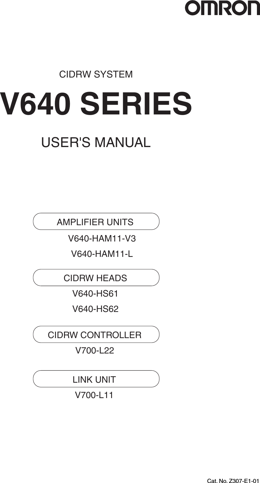

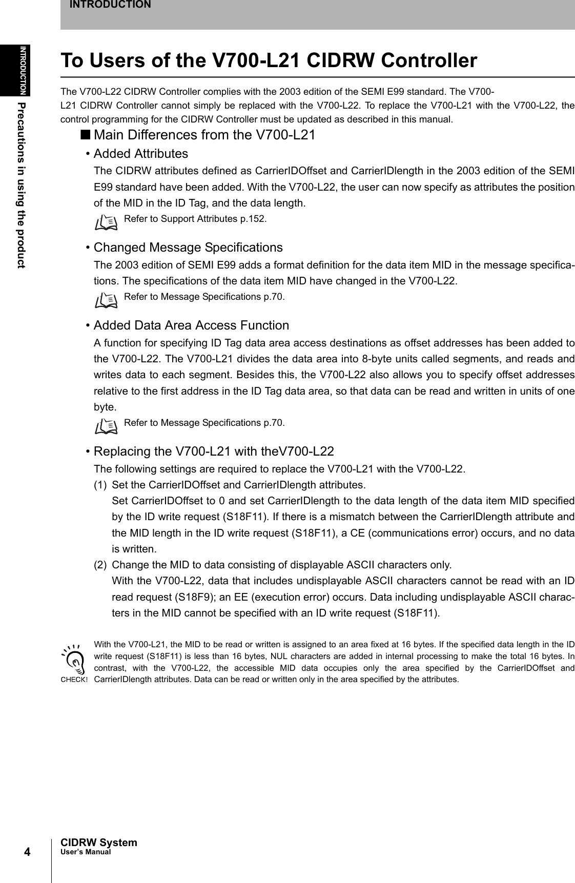
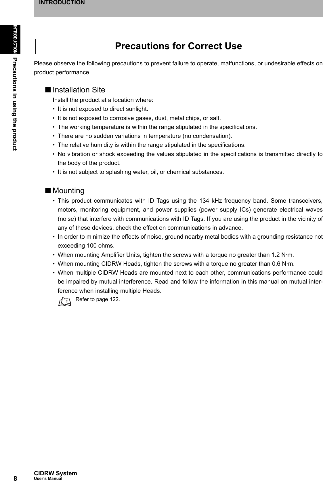
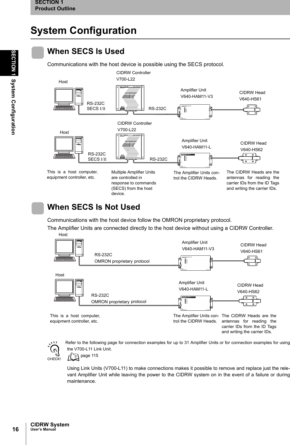
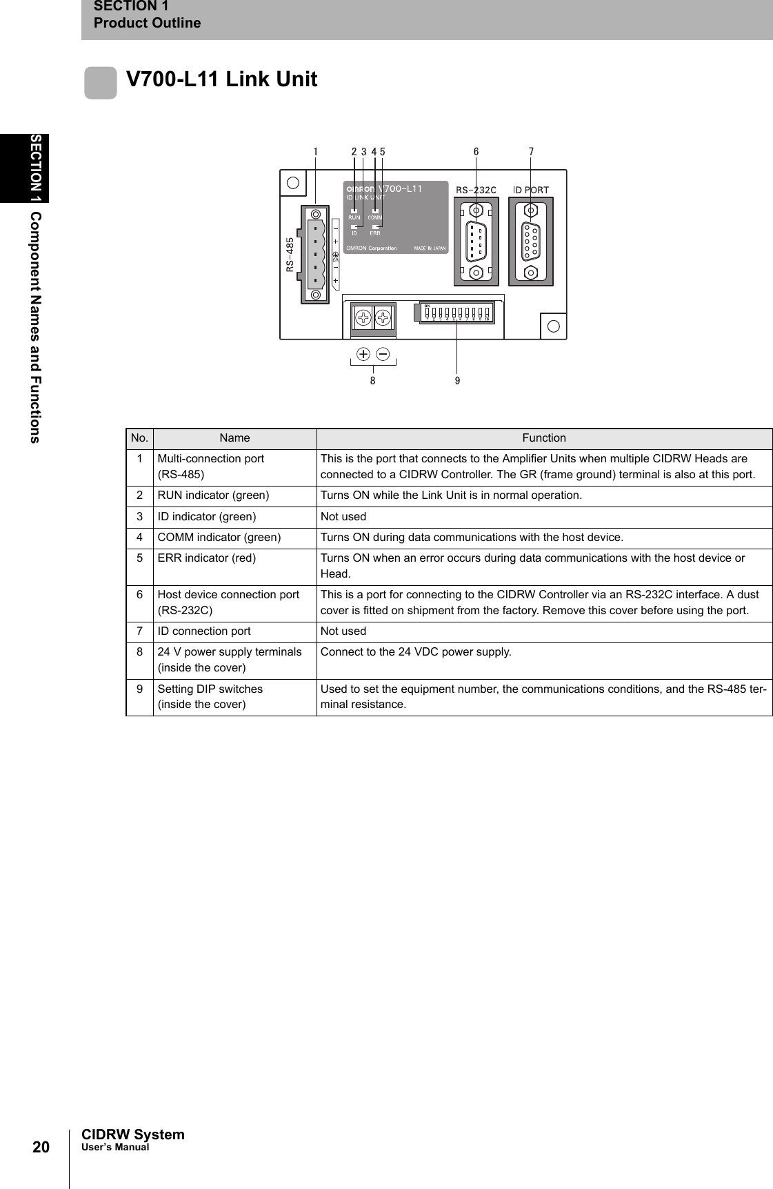
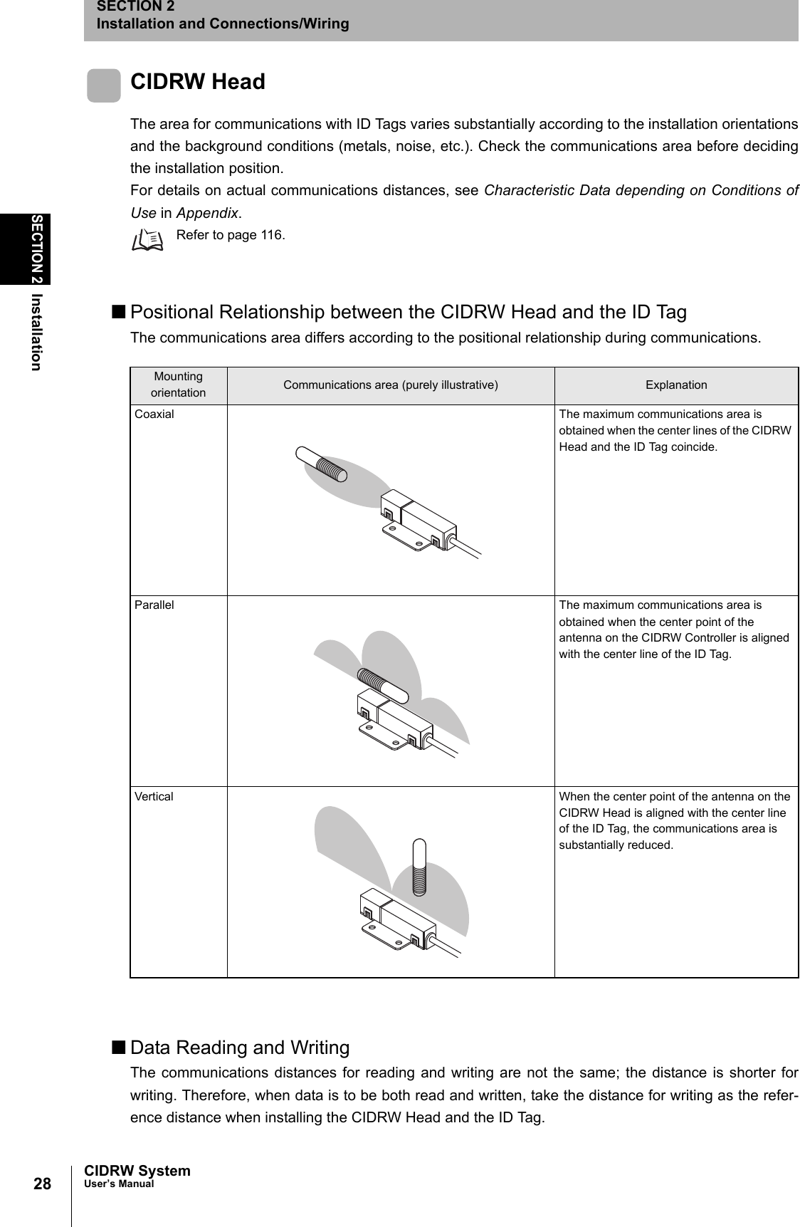
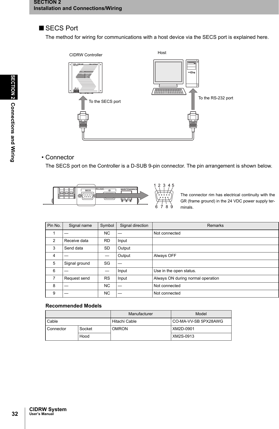
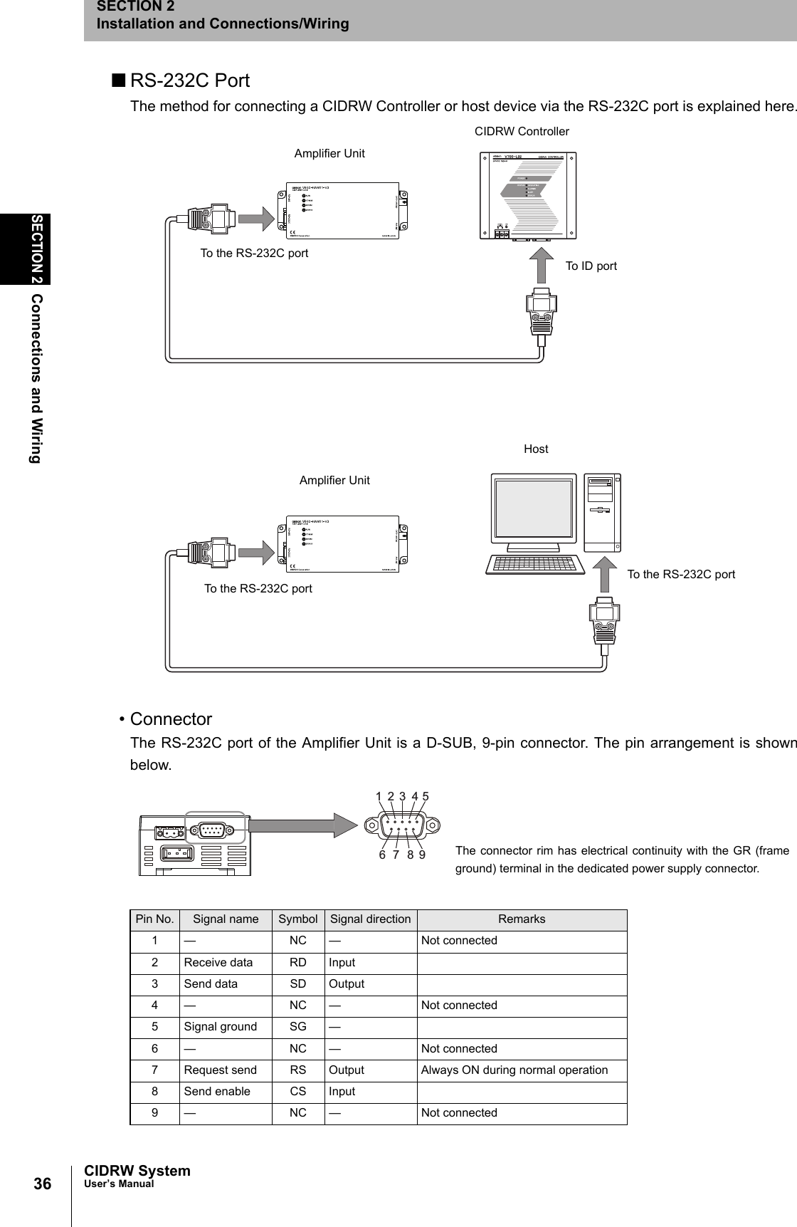
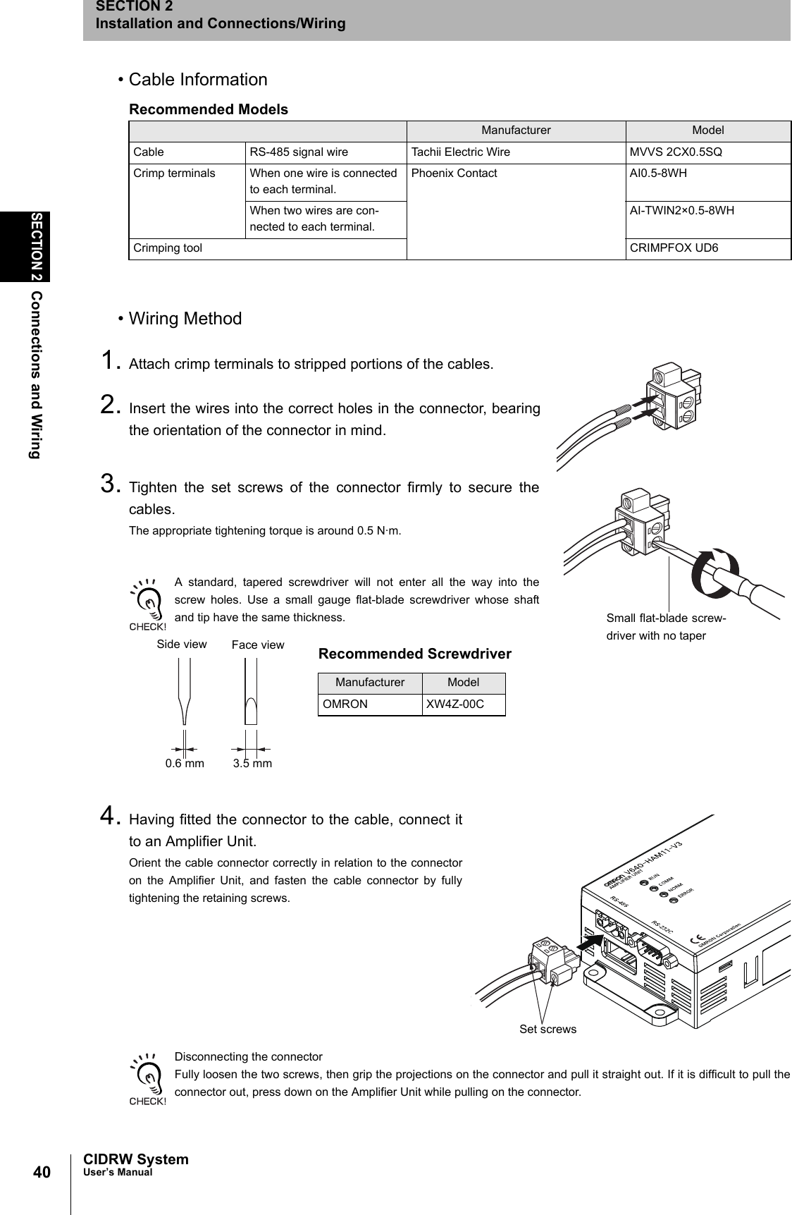
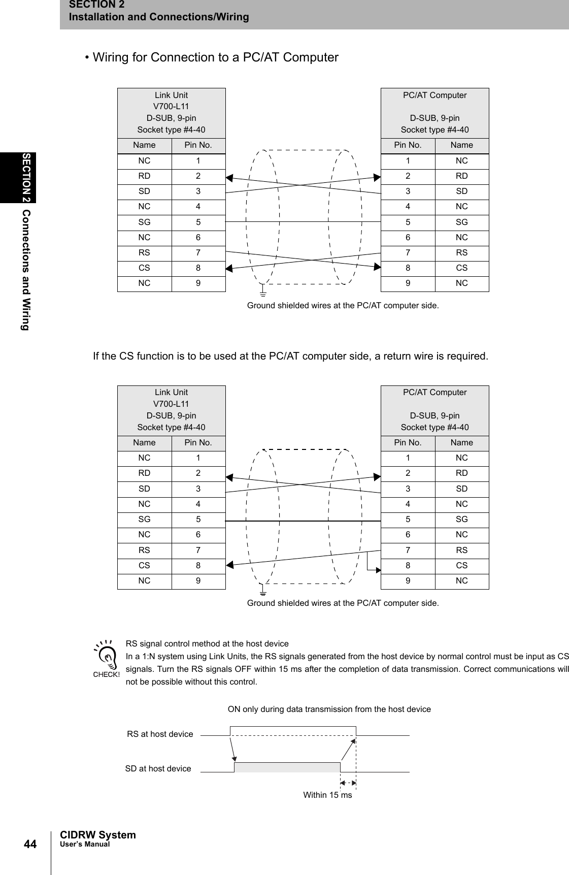
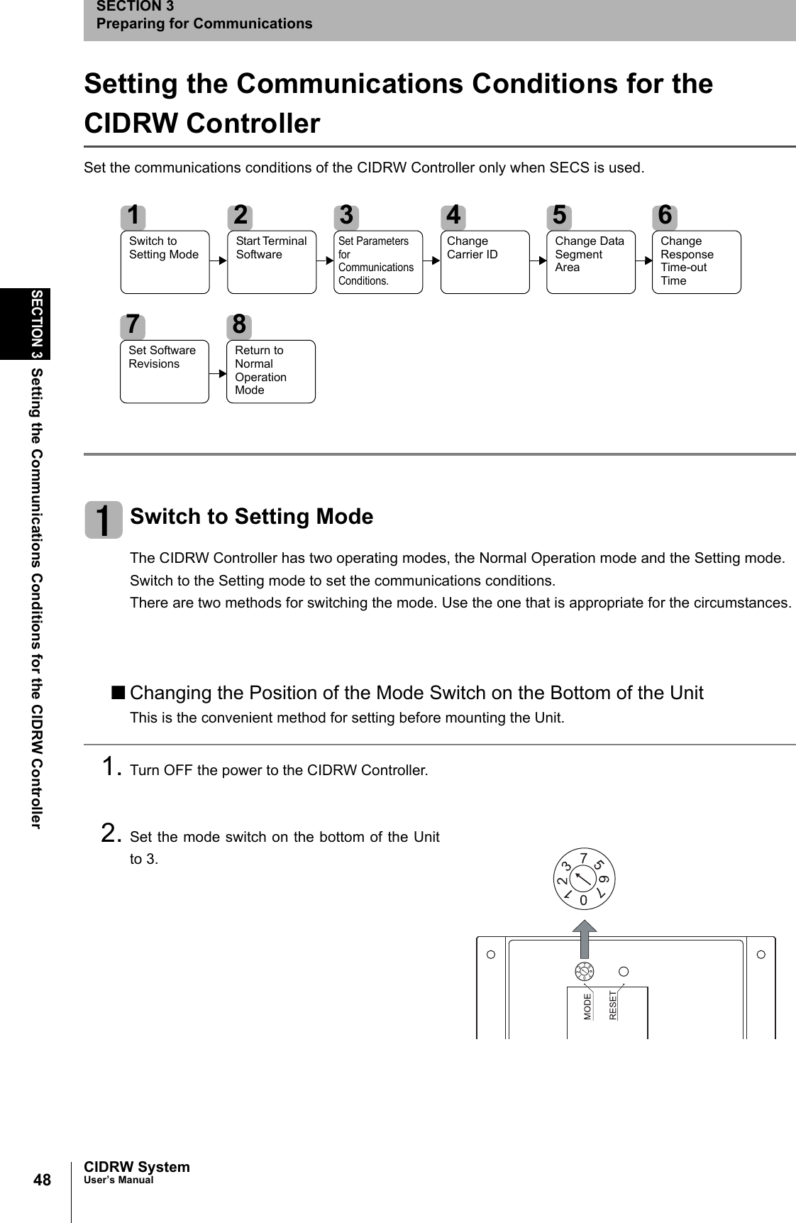
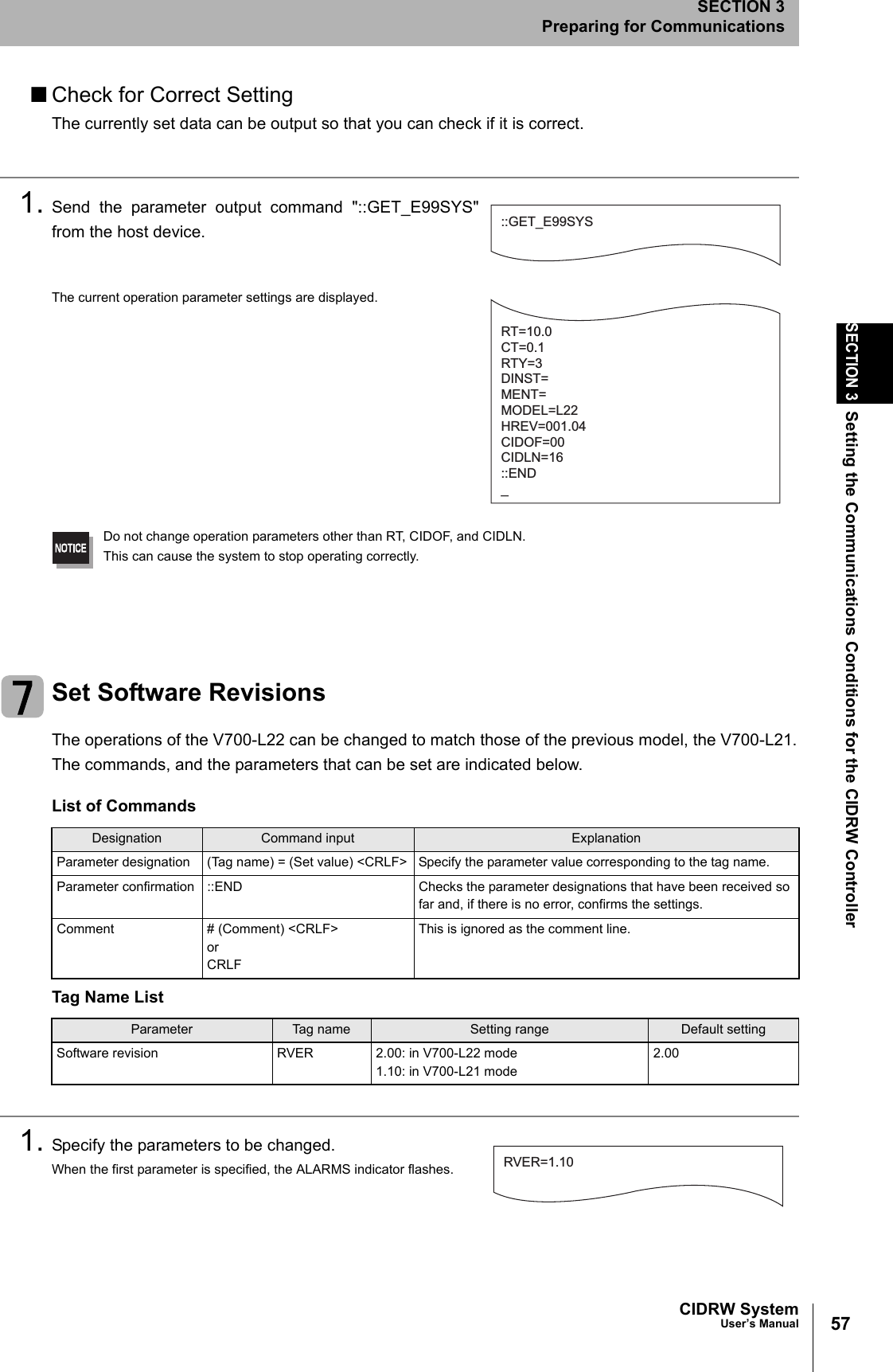
![49CIDRW SystemUser’s ManualSECTION 3Setting the Communications Conditions for the CIDRW ControllerSECTION 3Preparing for Communications3. When all of the devices to be used are connected, turn the power ON.The system starts up in the Setting mode, and the indicators react as shown below.■Sending a Switching Command from the Host DeviceThis method is convenient when the Unit has already been mounted and the switch on the bottom can-not be repositioned to 3.During operation in the Normal Operation mode, a command is sent from the host device to switch tothe Setting mode.1. Send a subsystem command (S18F13 ChangeState CPVAL1 = "PS") from the host device.Refer to page 77.CPVAL1="PS" is an expansion designation unique to V700-L22 and does not conform to SEMI standards.The system is automatically restarted and the mode switches to the Setting mode.The operation indicators react as shown below.Start Terminal SoftwareUse terminal software at the host device to set the CIDRW Controller.The commands and communications conditions in the setting mode are unique to OMRON. They do not conform to theSEMI standards. For the terminal software, use Hyper Terminal, which is standard with Windows, or a similar program.The communications conditions for communications between the host device and CIDRW Controllerare fixed. Make the following settings using the terminal software.OPERATING ALARMS BUSY ERROROPERATING ALARMS BUSY ERRORItem SettingBaud rate 9600 bpsData length 8 bitsParity EVENStop bits 1Communications control NoneSend code At the end of a line (when [ENTER] is input), the line feed characters ([LF]) are appended.Display Local echo](https://usermanual.wiki/Omron/V640HAM11L.User-manual1-L/User-Guide-1350878-Page-51.png)
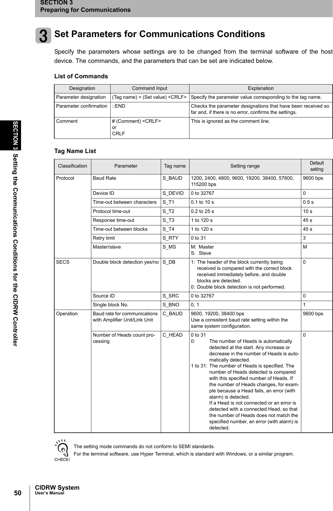
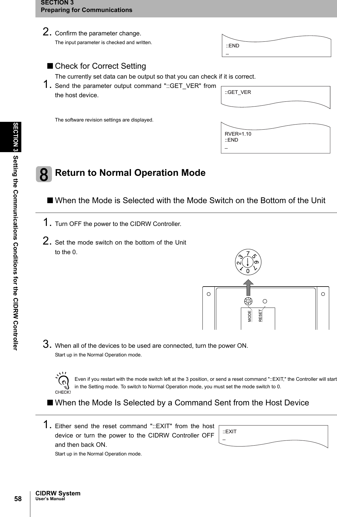
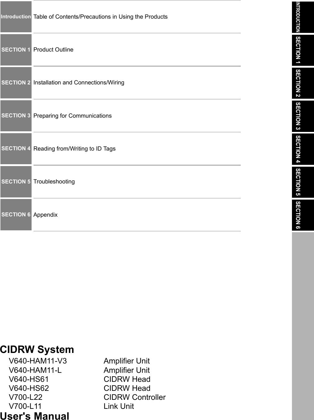
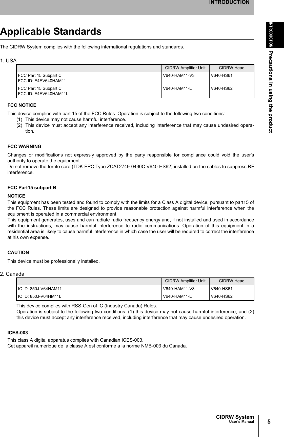
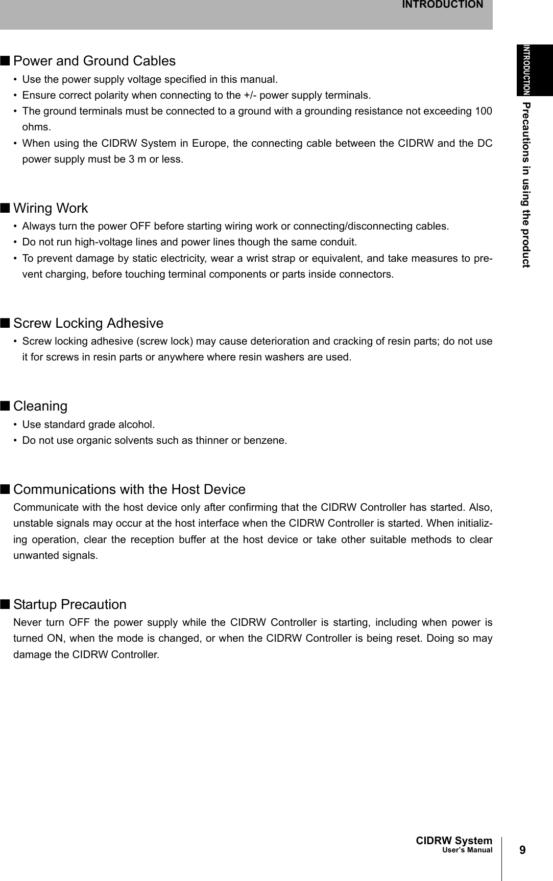
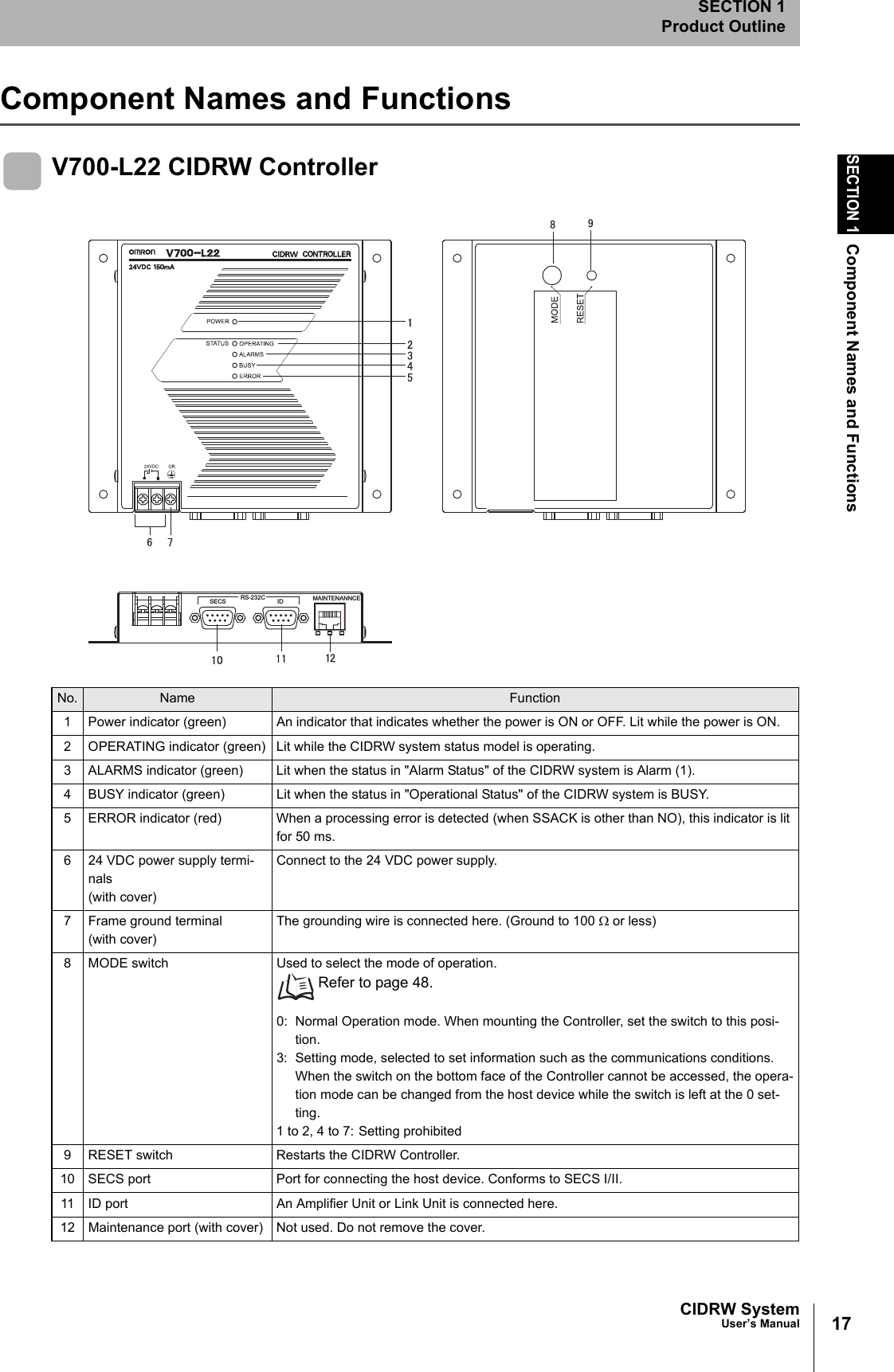
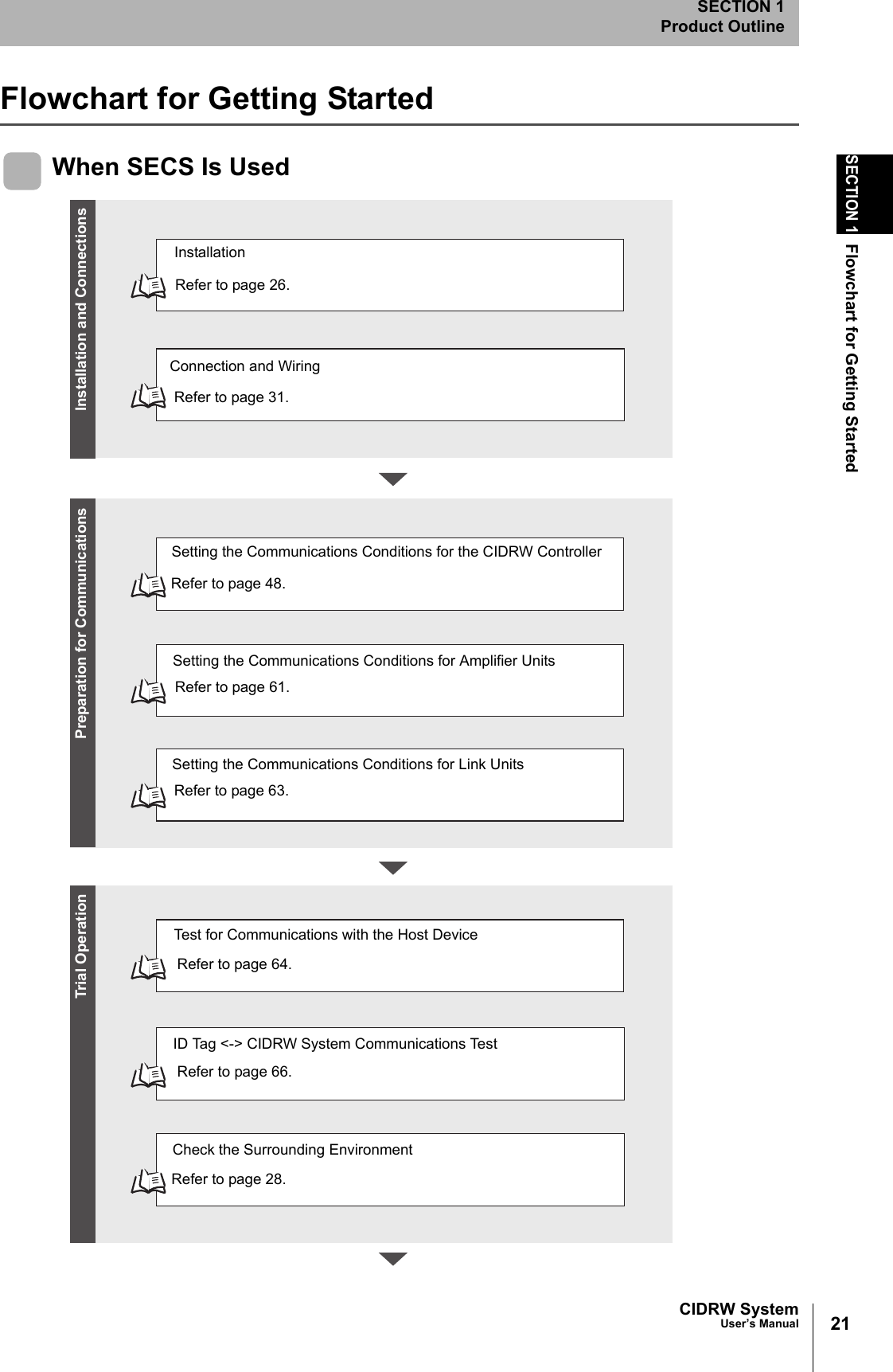
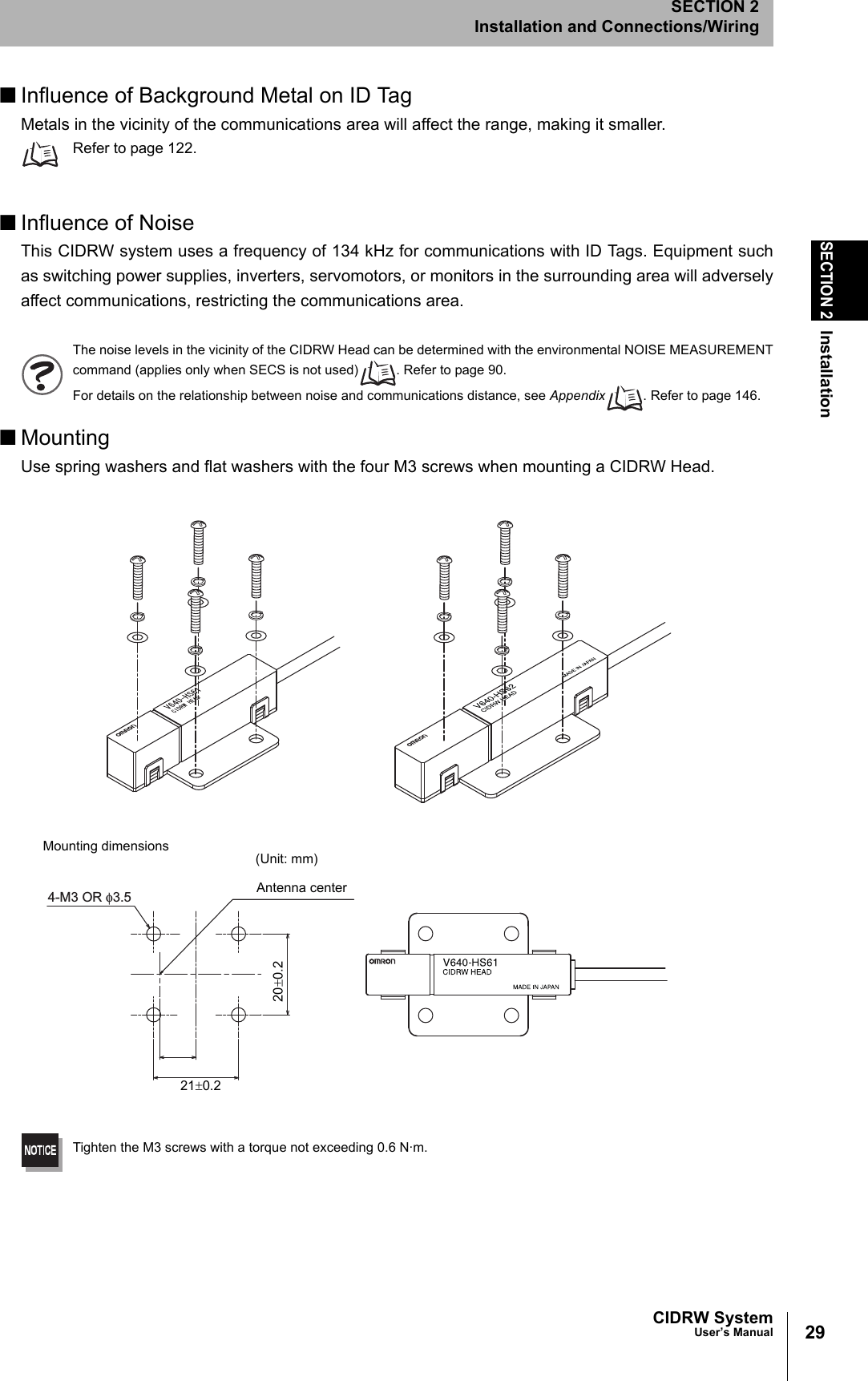
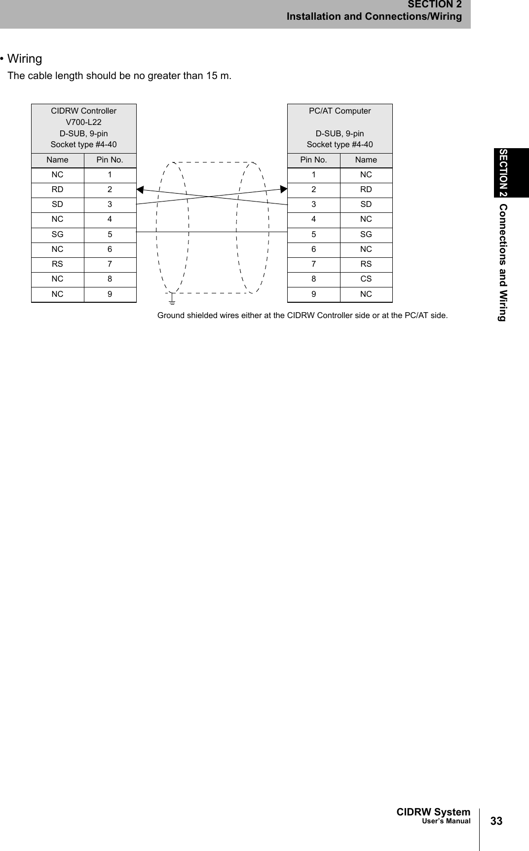
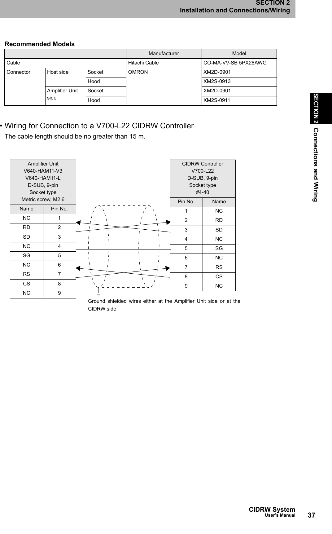
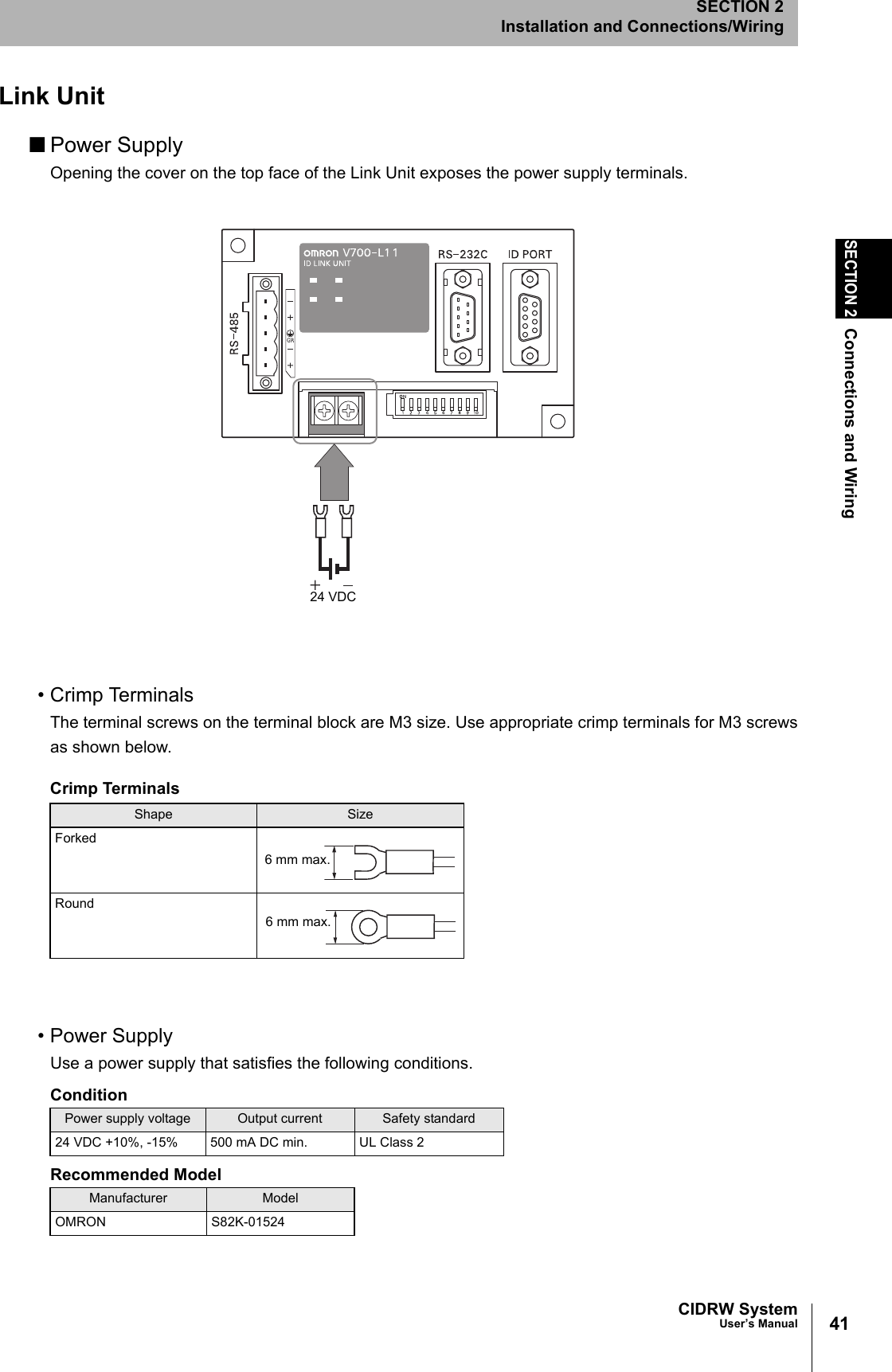
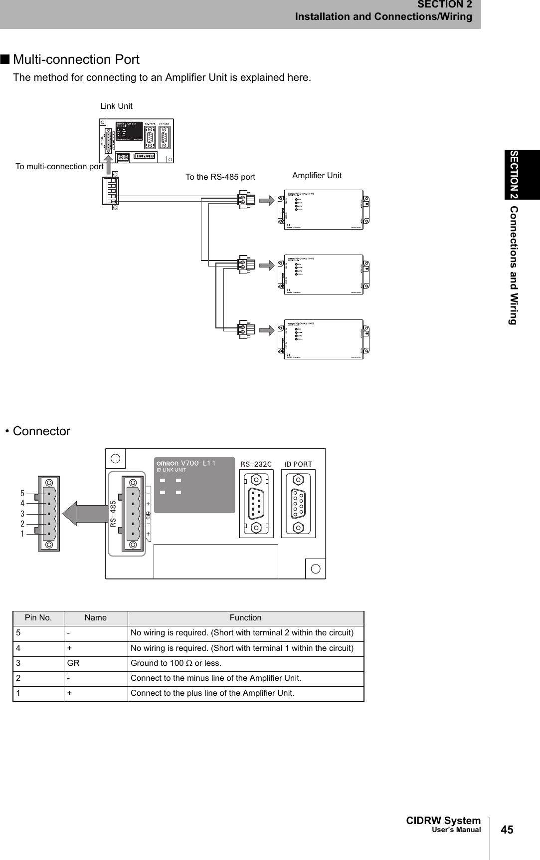
![51CIDRW SystemUser’s ManualSECTION 3Setting the Communications Conditions for the CIDRW ControllerSECTION 3Preparing for Communications1. Specify the parameters to be changed.When the first parameter is specified, the ALARMS indicator flashes.2. Confirm the parameter change.The input parameter is checked and written.When writing is completed, a message indicating the result is displayed.The ALARMS indicator lights.If writing is completed with an error, the parameters are not updated.The figure in square brackets [ ] indicates the line number where theerror was first detected. If a parity error is detected in the received char-acters, this figure is [0].Check the sent data based on this information.A text file is created based on the data that is keyed in, as shown below, and this data can be conveniently transmittedusing the terminal's text file send function.S_BAUD=19200S_DEVID=1S_BNO=0_::END _SETUP_COMPLETE_SETUP_FAILED [2]_When writing is completed without errorWhen writing is completed with an error#Parameter Setting File for SystemA#ProtocolS_BAUD=19200S_DEVID=1#SECSS_BNO=0::ENDExample: PRM.TXT](https://usermanual.wiki/Omron/V640HAM11L.User-manual1-L/User-Guide-1350878-Page-53.png)
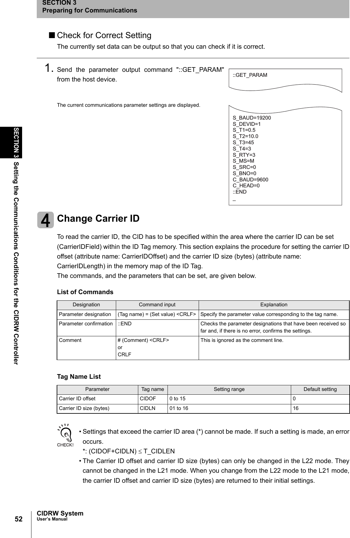
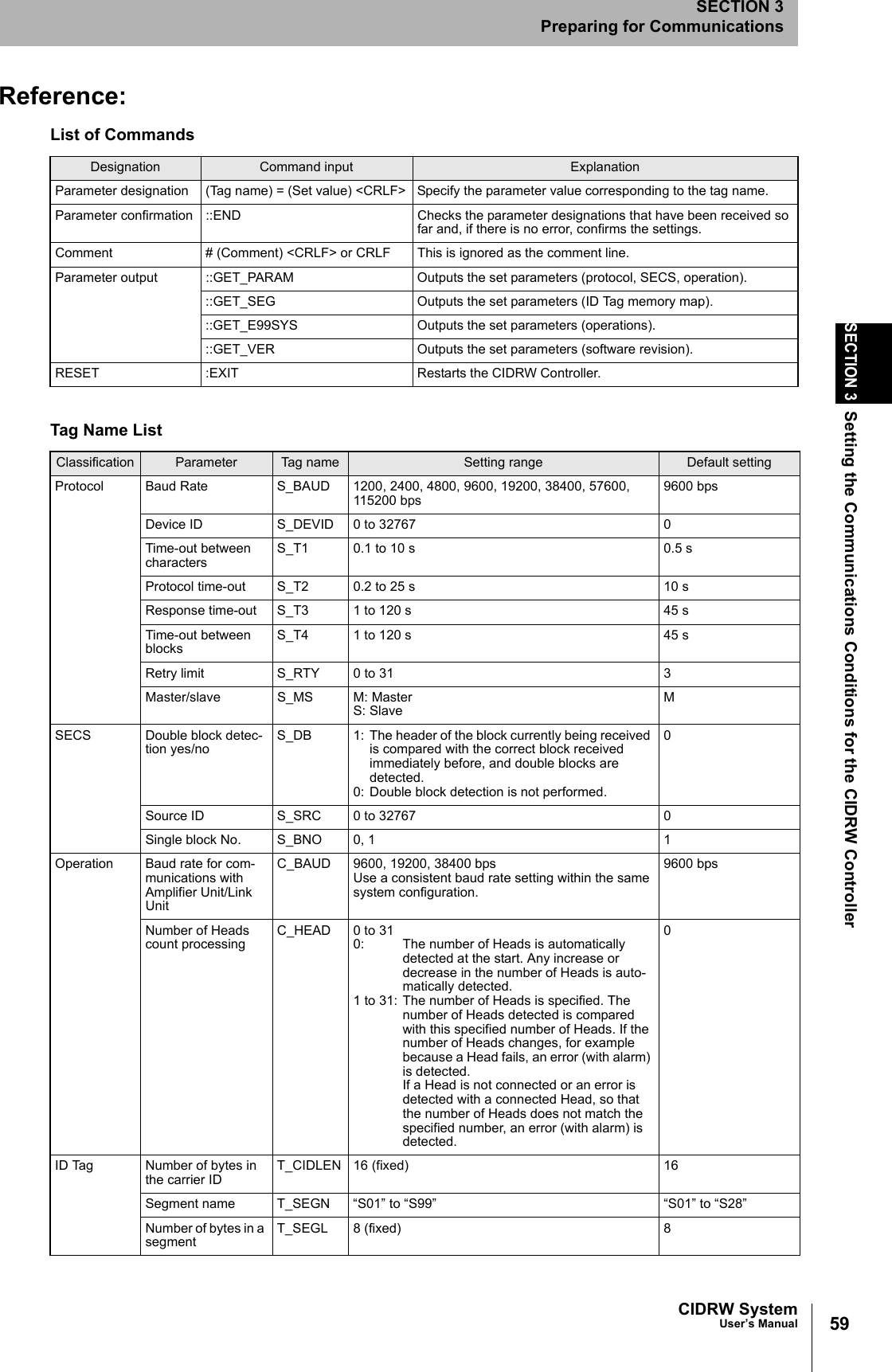
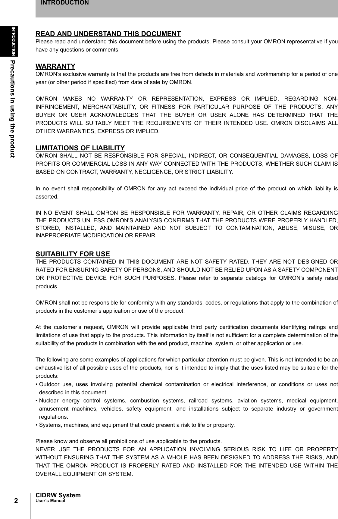
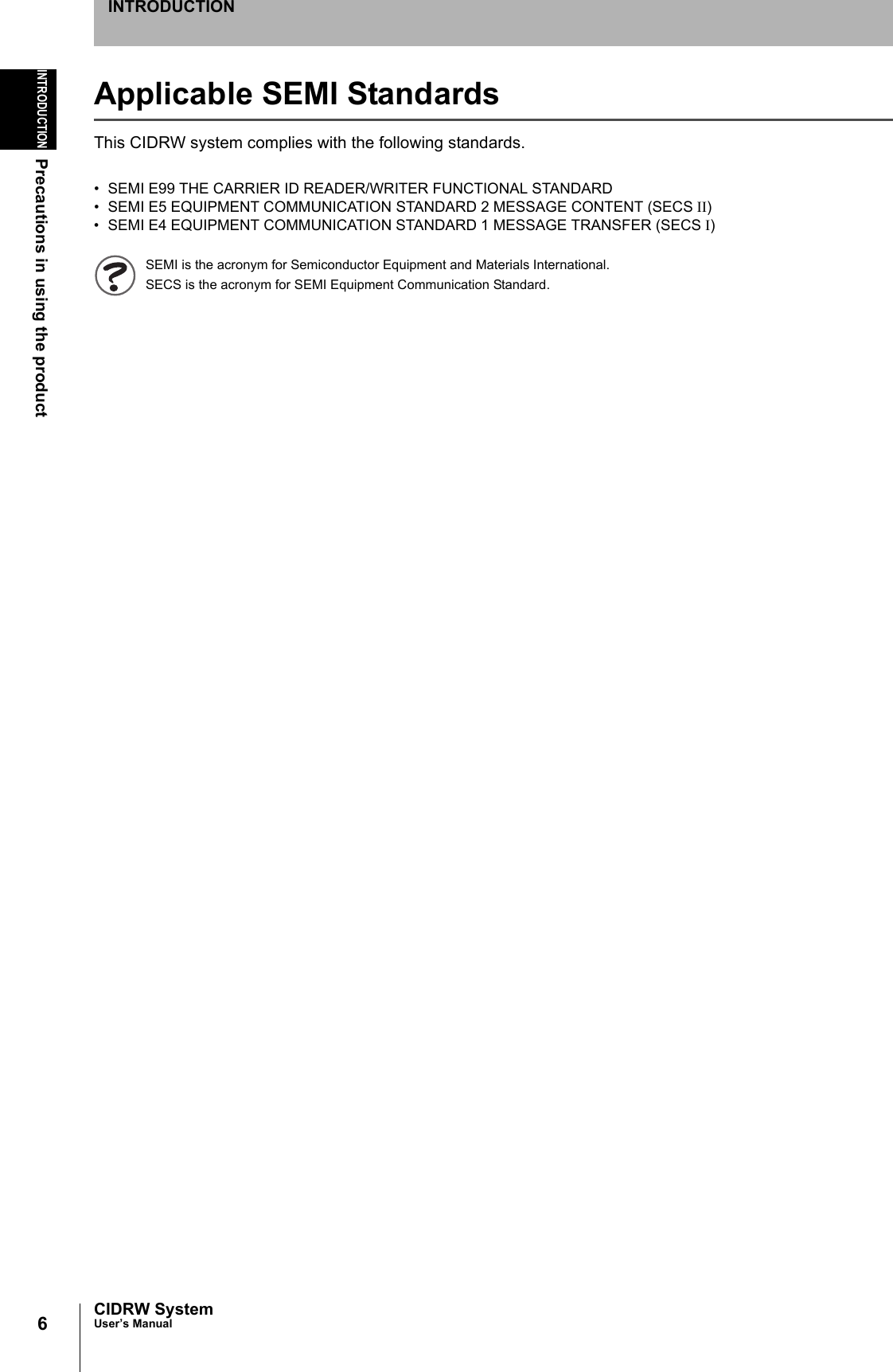
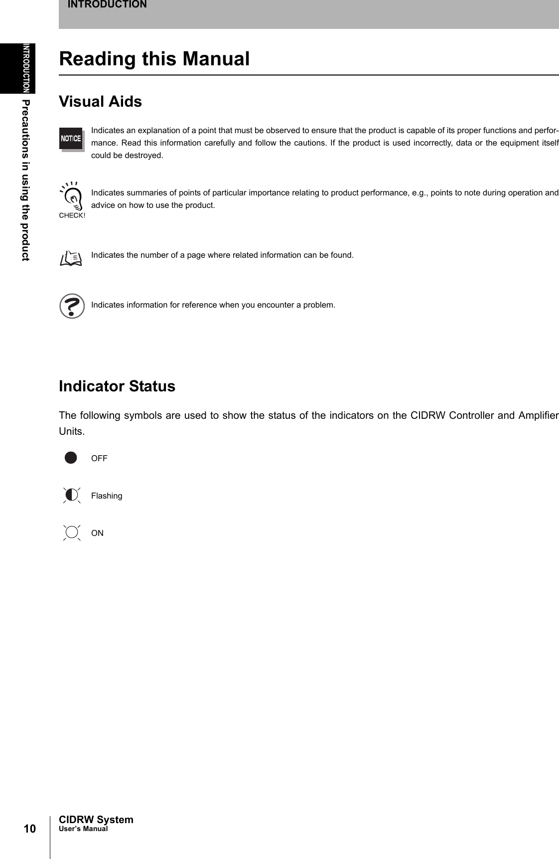
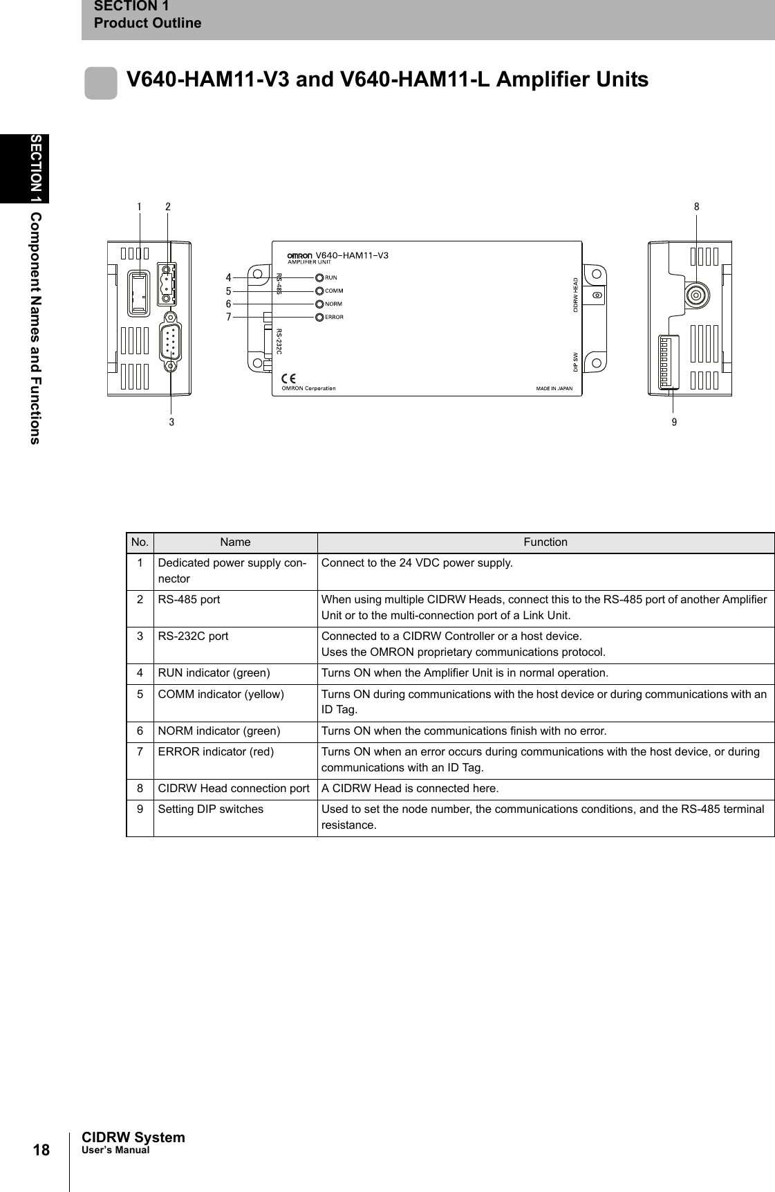
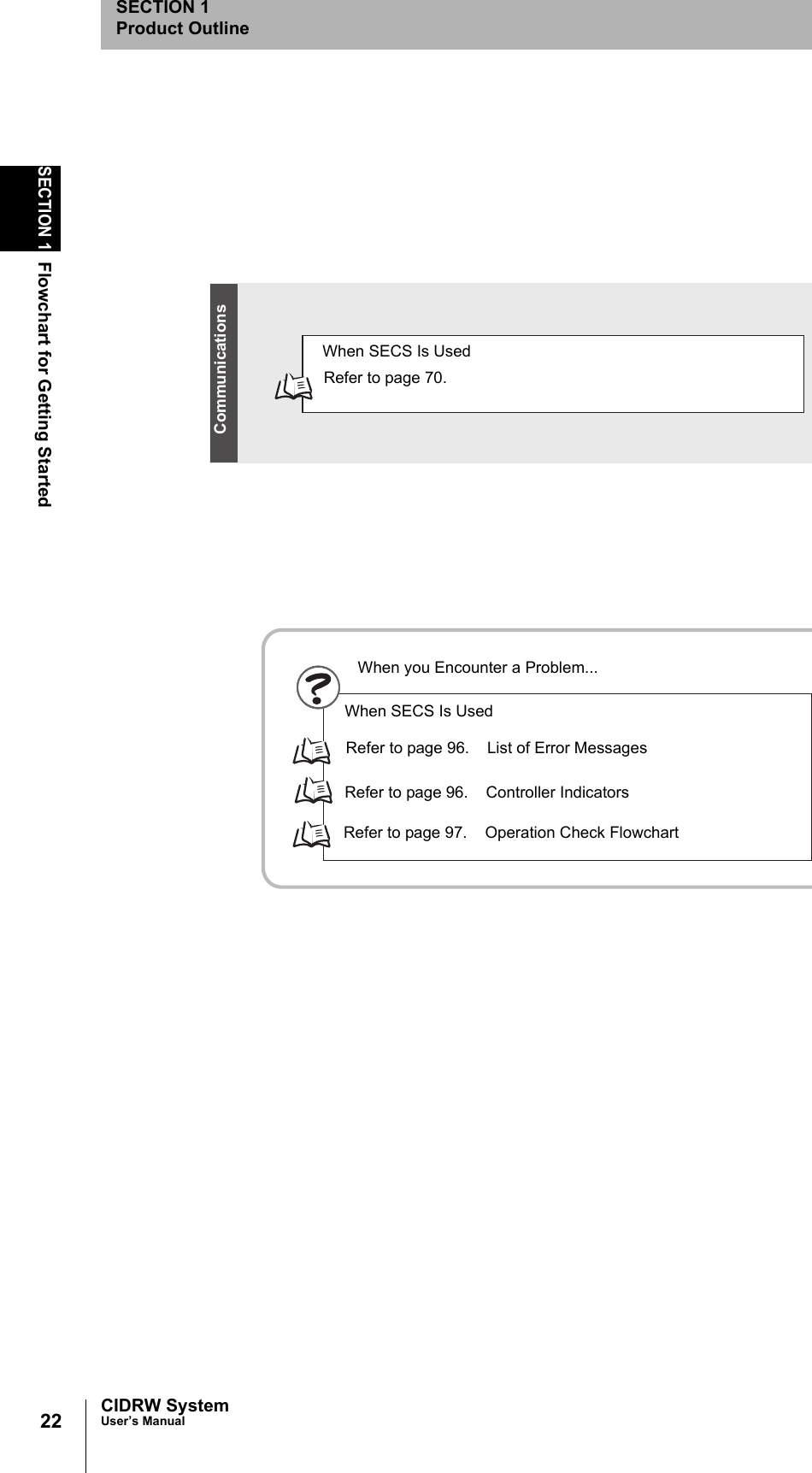
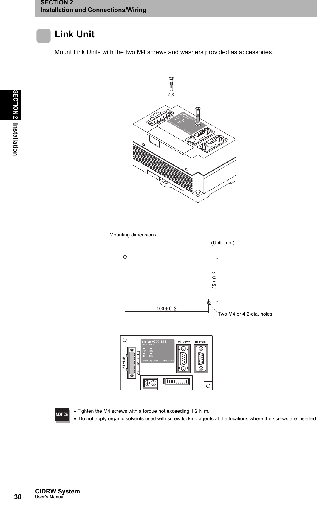
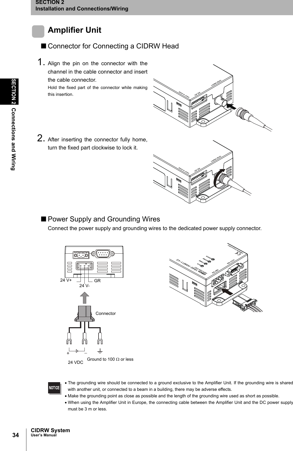
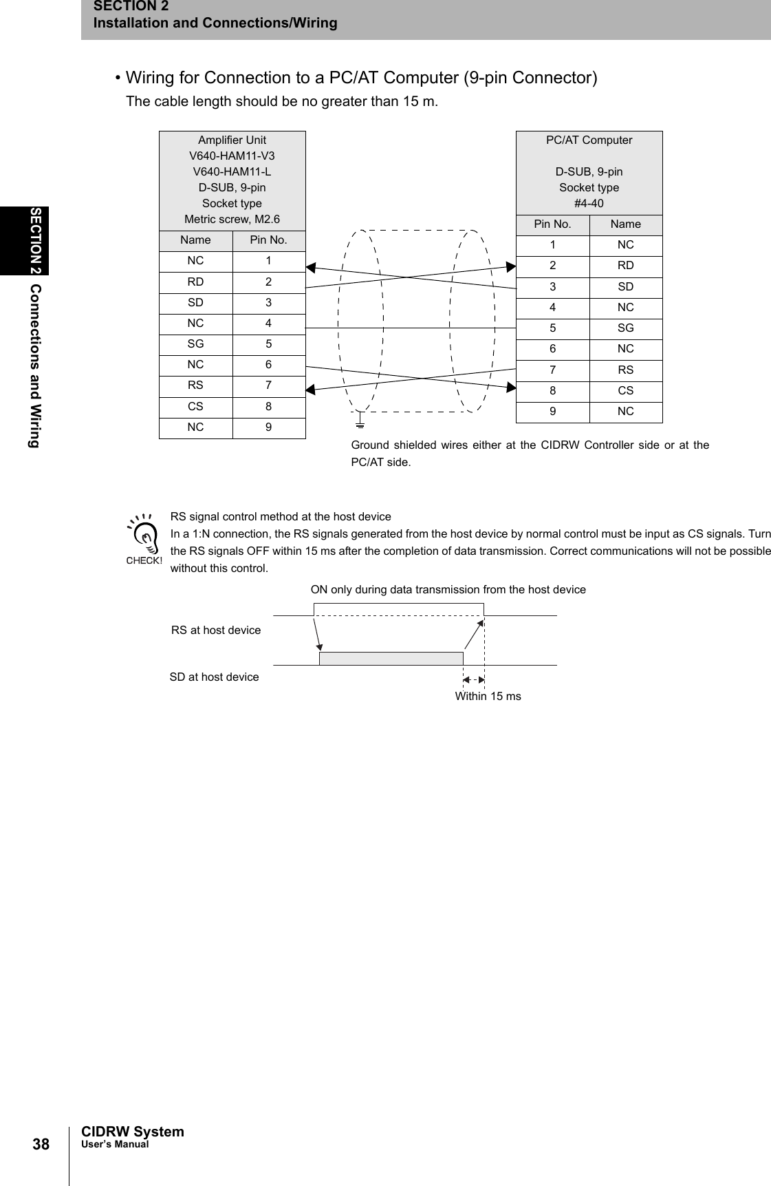
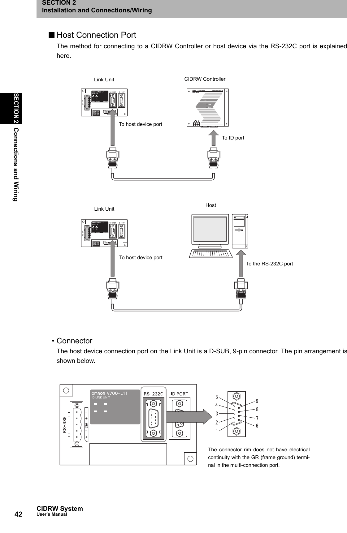
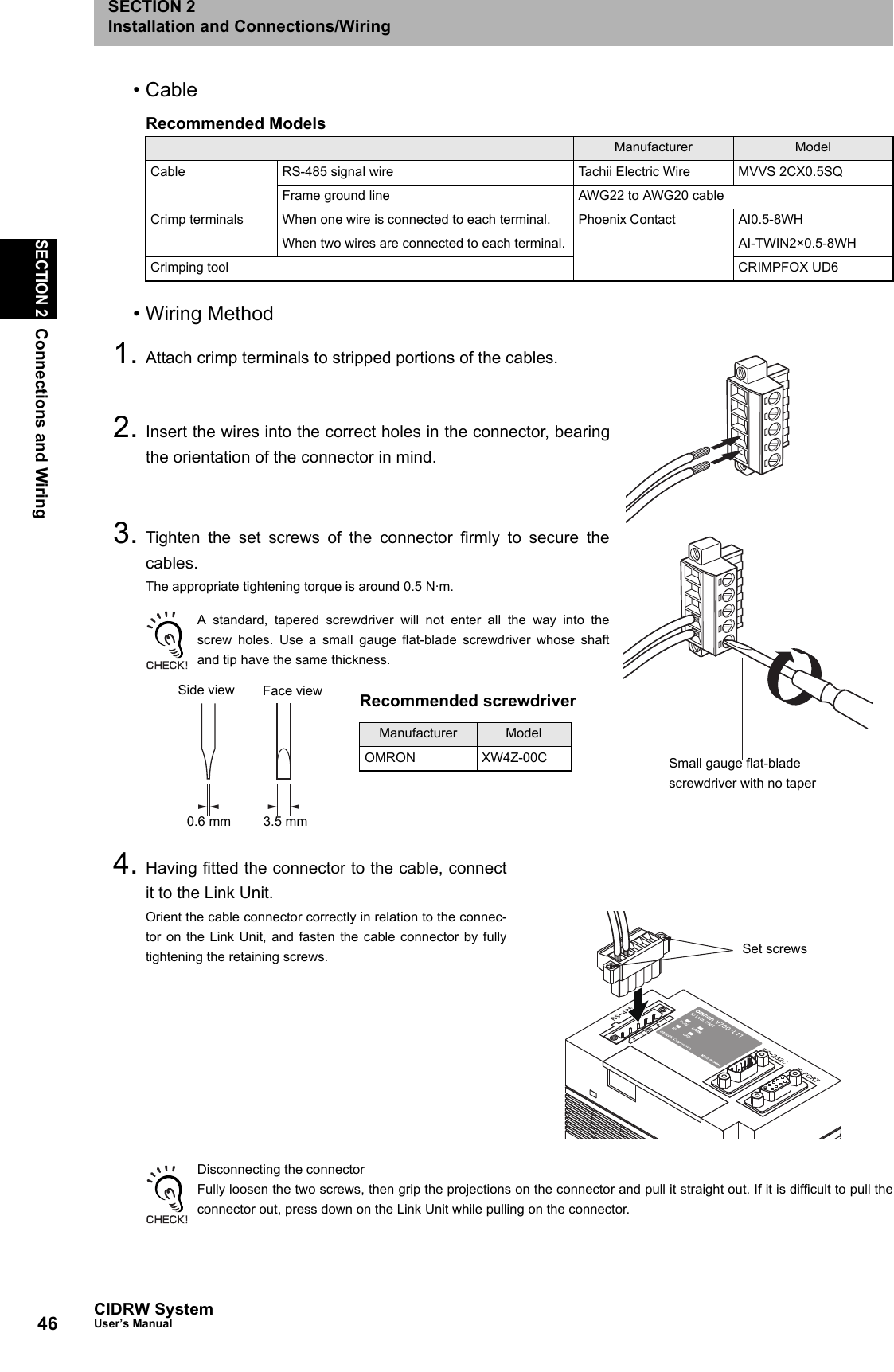
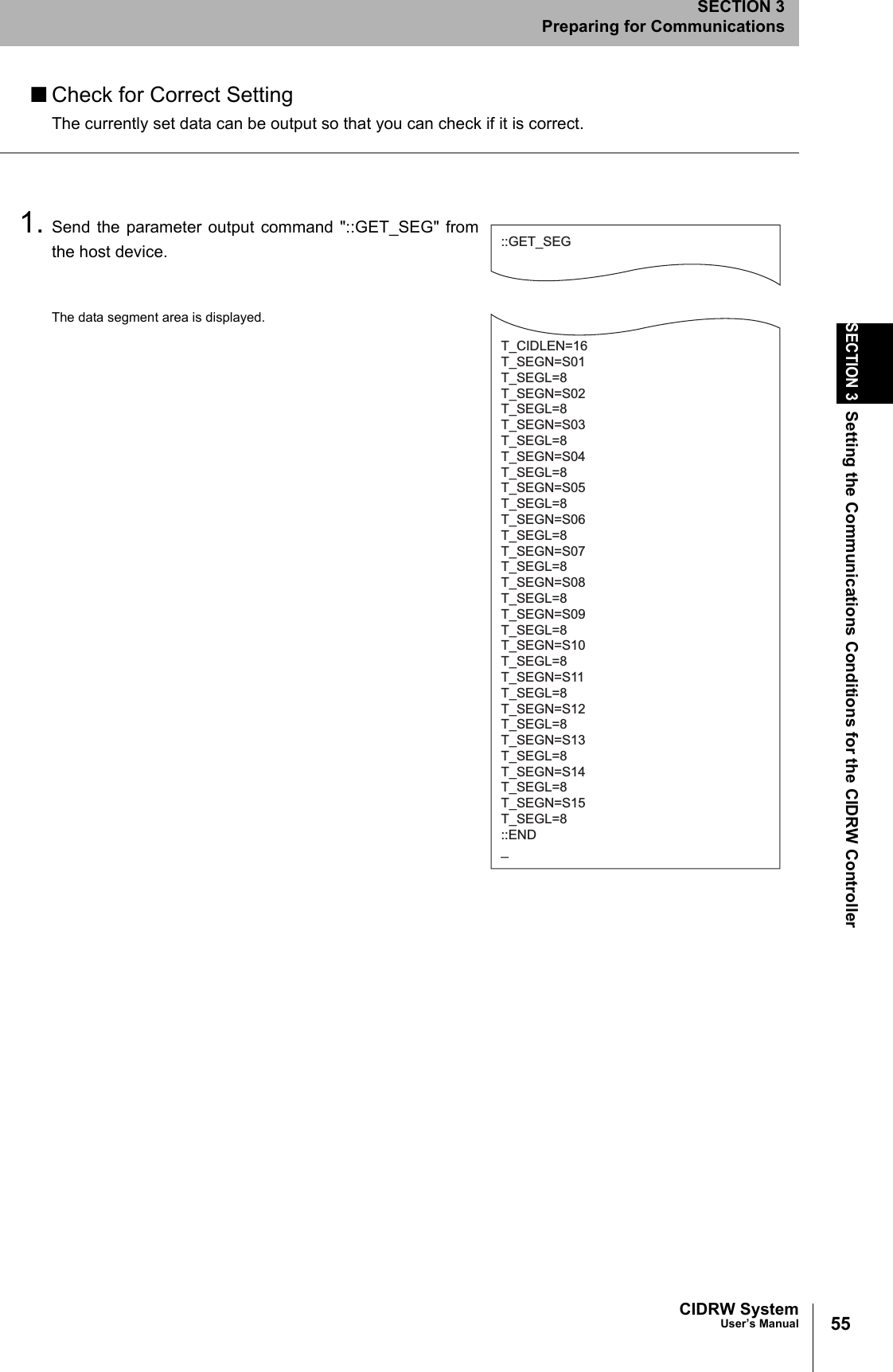
![54SECTION 3Setting the Communications Conditions for the CIDRW ControllerCIDRW SystemUser’s ManualSECTION 3Preparing for Communications1. The form of the input from the host device is shown in thefigure to the right.When the first parameter is specified, the ALARMS indicator flashes.2. Confirm the parameter change.The input parameter is checked and written.When writing is completed, a message indicating the result is displayed.The ALARMS indicator lights.If writing is completed with an error, the parameters are not updated.The figure in square brackets [ ] indicates the line number where theerror was first detected. If a parity error is detected in the received char-acters, this figure is [0].Check the sent data based on this information.Tag Name ListParameter Tag name Setting range Default settingNumber of bytes in the carrier ID T_CIDLEN 16 (fixed)The setting must maintain the following relationship(CIDOF + CIDLN) ≤ T_CIDLEN16Segment name T_SEGN "S01" to "S99" "S01" to "S28"Number of bytes in a segment T_SEGL 8 (fixed) 8T_CIDLEN=16T_SEGN=S01T_SEGL=8T_SEGN=S02T_SEGL=8T_SEGN=S03T_SEGL=8T_SEGN=S04T_SEGL=8T_SEGN=S05T_SEGL=8T_SEGN=S06T_SEGL=8T_SEGN=S07T_SEGL=8T_SEGN=S08T_SEGL=8T_SEGN=S09T_SEGL=8T_SEGN=S10T_SEGL=8T_SEGN=S11T_SEGL=8T_SEGN=S12T_SEGL=8T_SEGN=S13T_SEGL=8T_SEGN=S14T_SEGL=8T_SEGN=S15T_SEGL=8_::END _SETUP_COMPLETE_SETUP_FAILED [2]_When writing is completed without errorWhen writing is completed with an error](https://usermanual.wiki/Omron/V640HAM11L.User-manual1-L/User-Guide-1350878-Page-56.png)
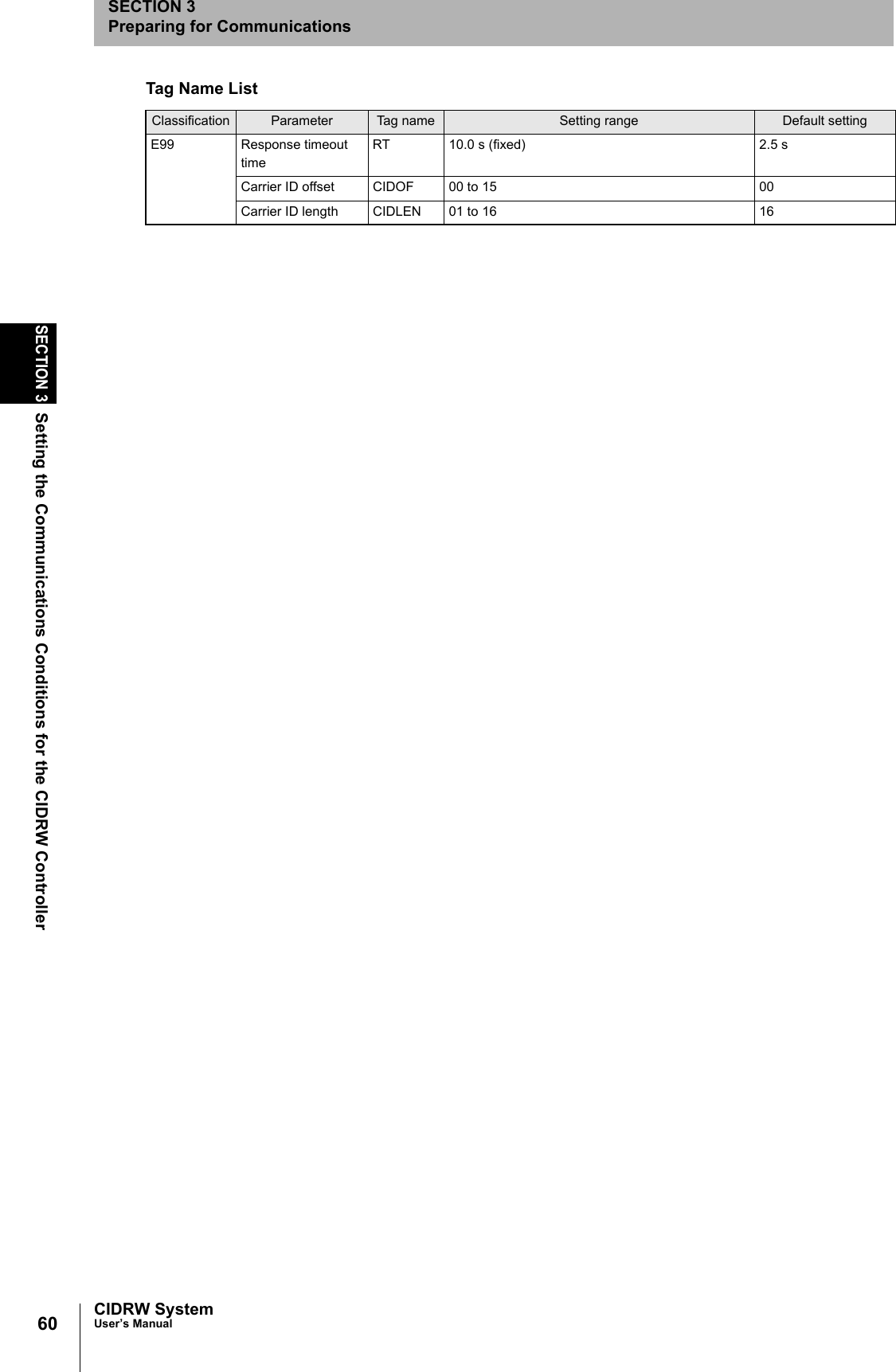
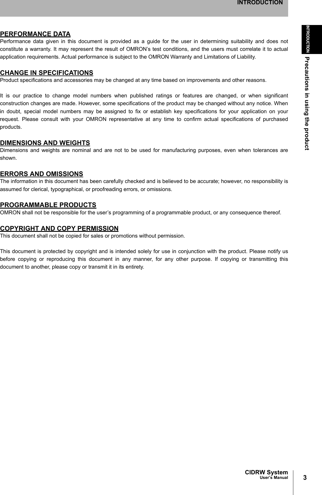
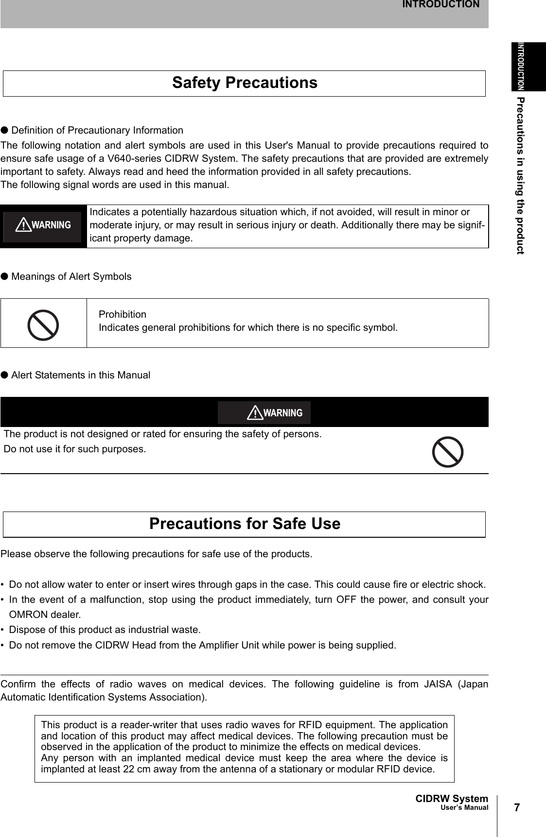
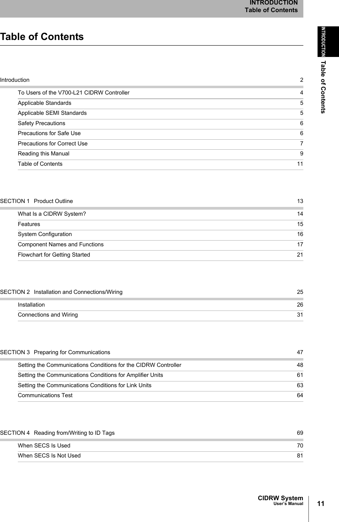
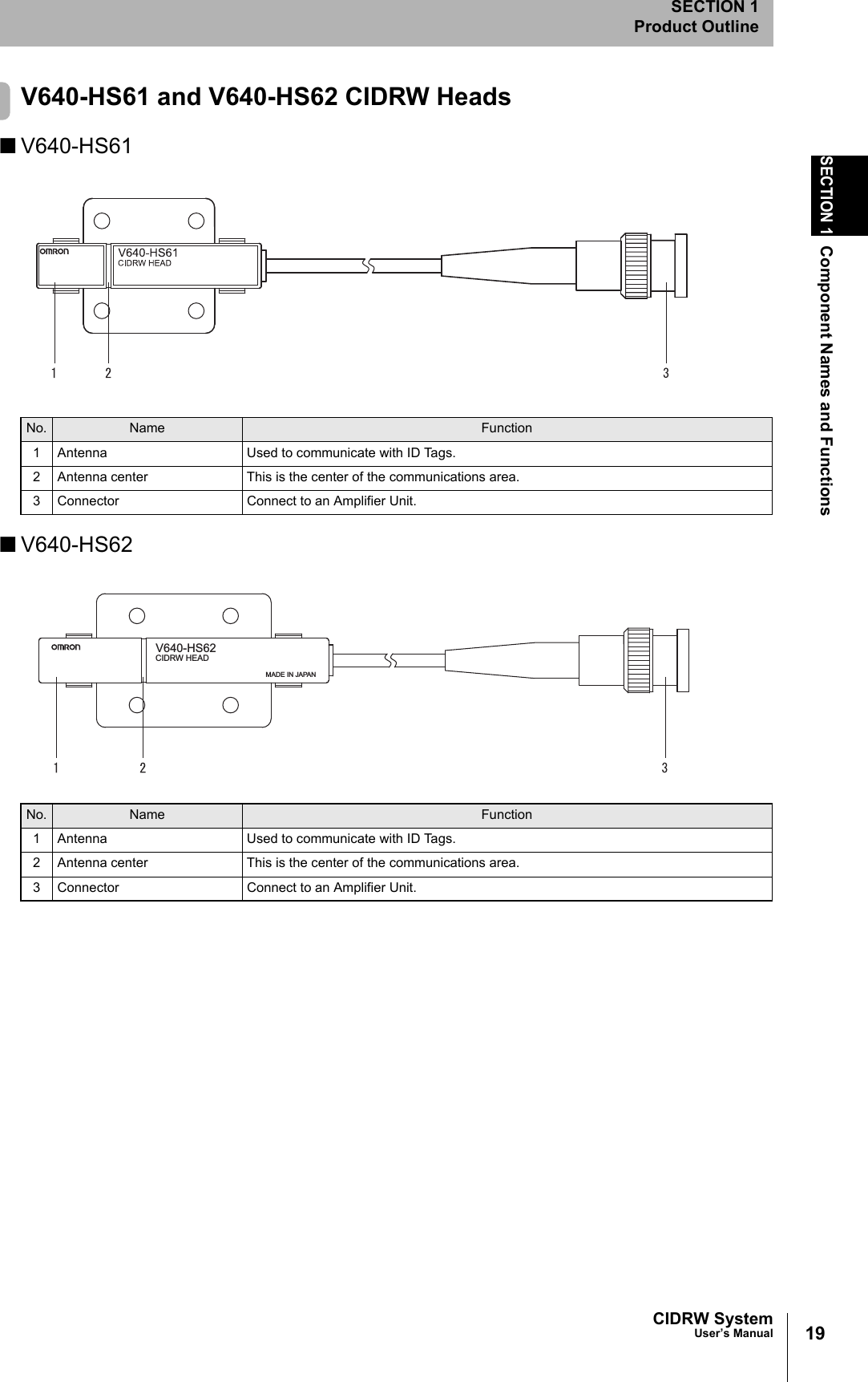
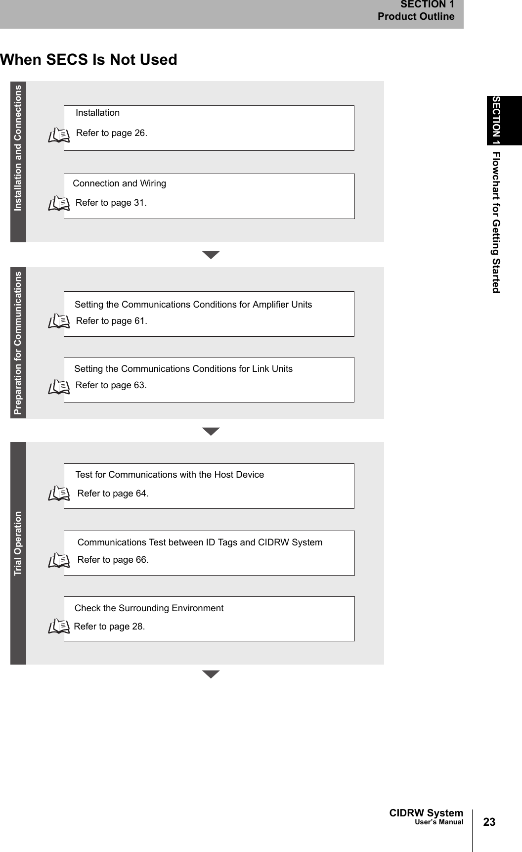
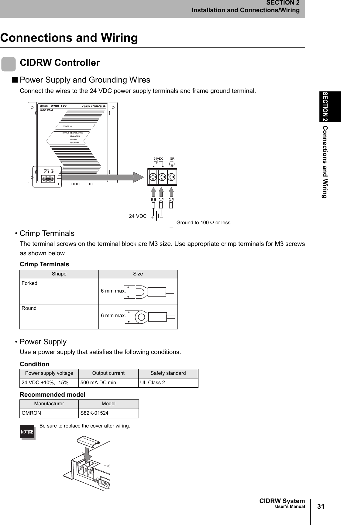
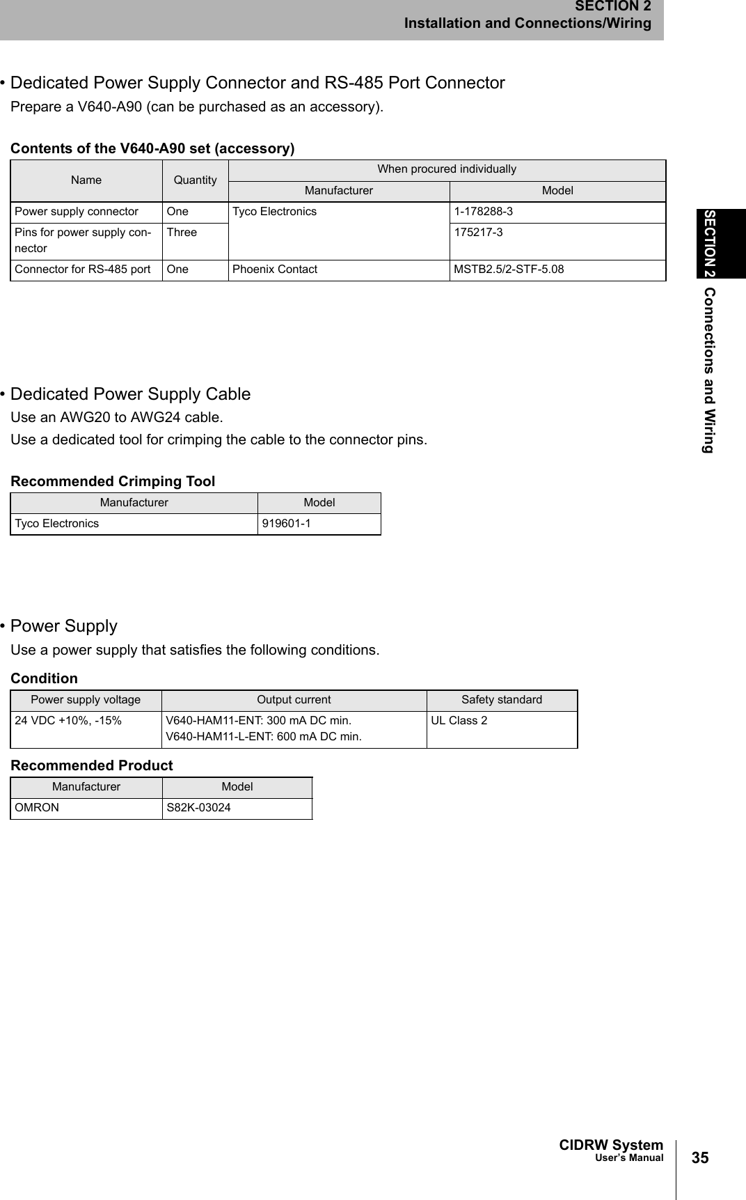
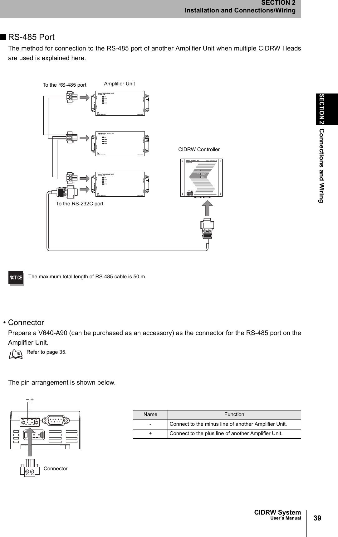
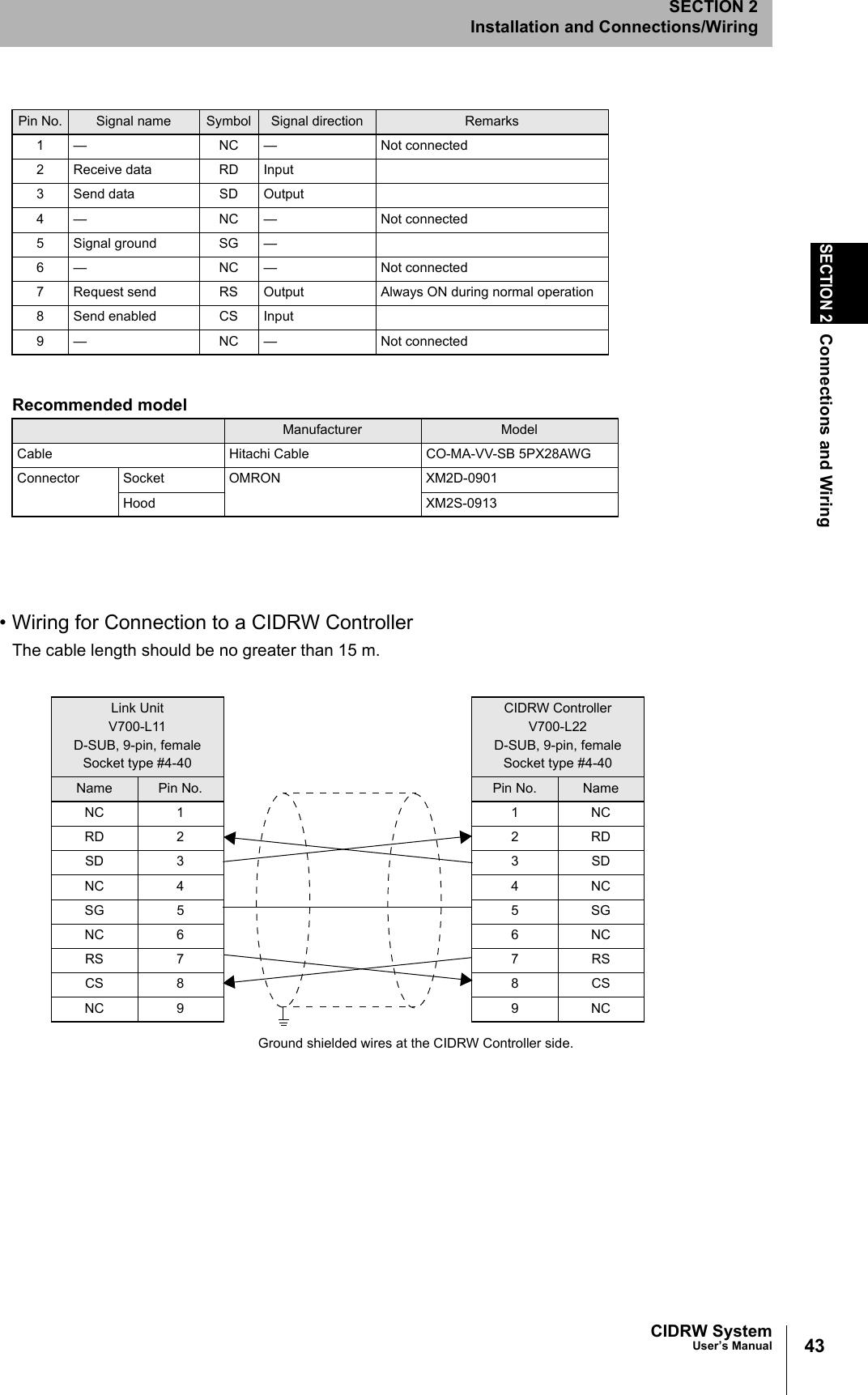
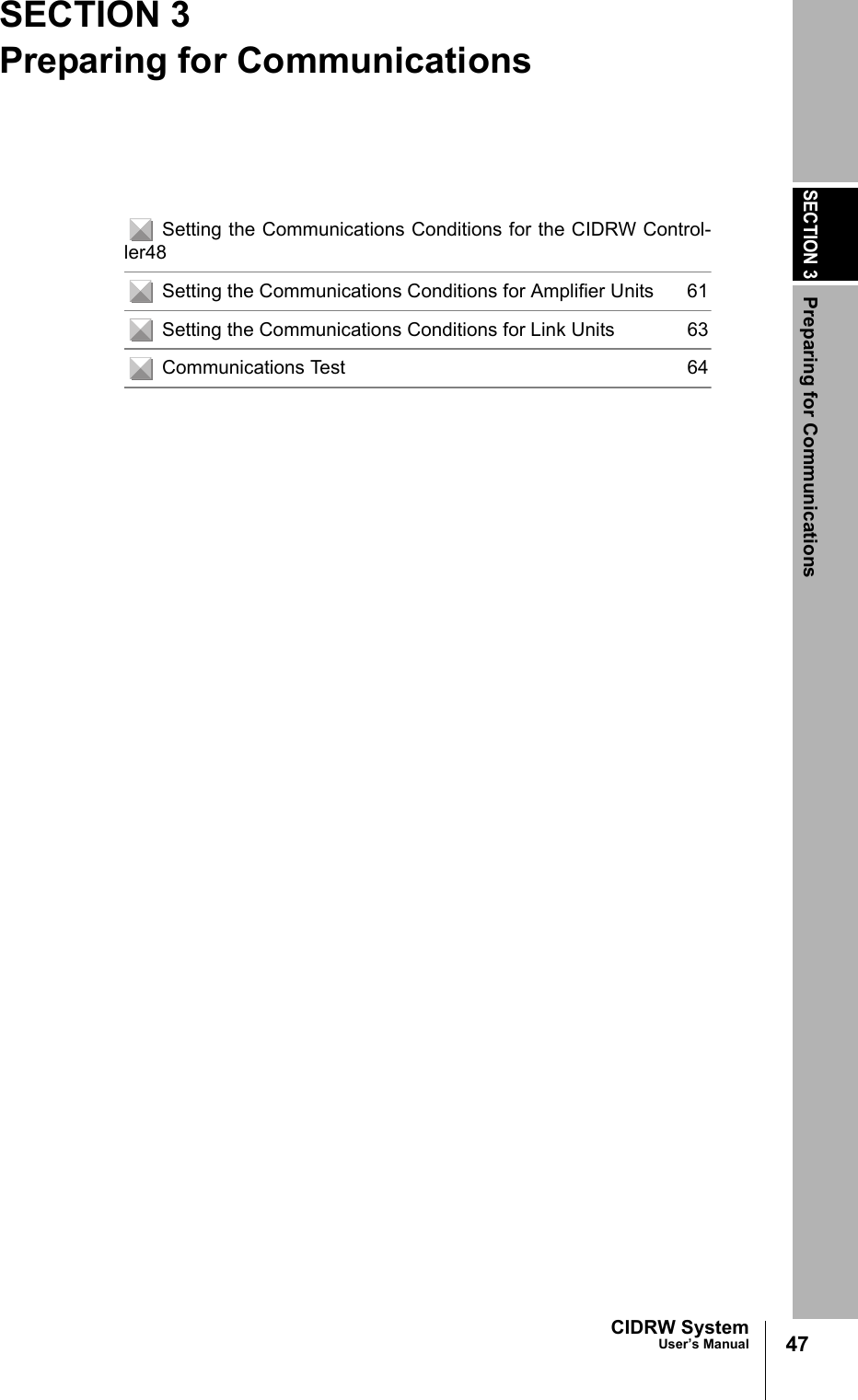
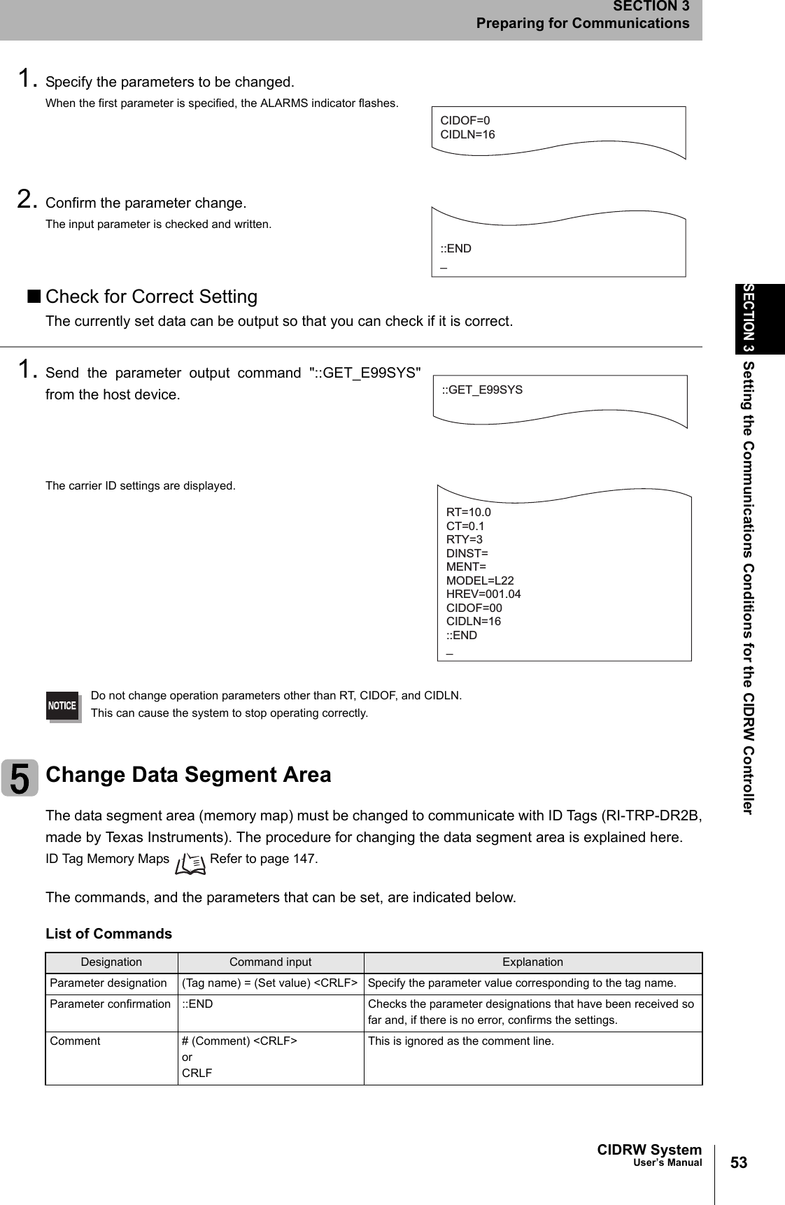
![56SECTION 3Setting the Communications Conditions for the CIDRW ControllerCIDRW SystemUser’s ManualSECTION 3Preparing for CommunicationsChange Response Time-out TimeIn the initial settings of the CIDRW Controller, when ID Tag (RI-TRP-DR2B, made by Texas Instru-ments) data is read or written, a response time-out may occur. Be sure to set the response time-outtime to 10 s.The commands, and the parameters that can be set are indicated below.1. Set the response time-out time to 10.0.2. Confirm the parameter change.The input parameter is checked and written.When writing is completed, a message indicating the result is displayed.The ALARMS indicator lights.If writing is completed with an error, the parameters are not updated.The figure in square brackets [ ] indicates the line number where theerror was first detected. If a parity error is detected in the received char-acters, this figure is [0].Check the sent data based on this information.List of CommandsDesignation Command input ExplanationParameter designation (Tag name) = (Set value) <CRLF> Specify the parameter value corresponding to the tag name.Parameter confirmation ::END Checks the parameter designations that have been received so far and, if there is no error, confirms the settings.Comment # (Comment) <CRLF> or CRLFThis is ignored as the comment line.Tag Name ListParameter Tag name Setting range Default settingResponse time-out time RT 10.0 (fixed) 2.5RT=10.0_::END _SETUP_COMPLETE_SETUP_FAILED [2]_When writing is completed without errorWhen writing is completed with an error](https://usermanual.wiki/Omron/V640HAM11L.User-manual1-L/User-Guide-1350878-Page-58.png)