Omron V78068 RFID READER/WRITER User Manual 9309087 4A V780 HMD68 ETN US
Omron Corporation RFID READER/WRITER 9309087 4A V780 HMD68 ETN US
UserManual.wiki
>
Omron
>
V78068 User Manual
>
Users manual-1
Contents
1.
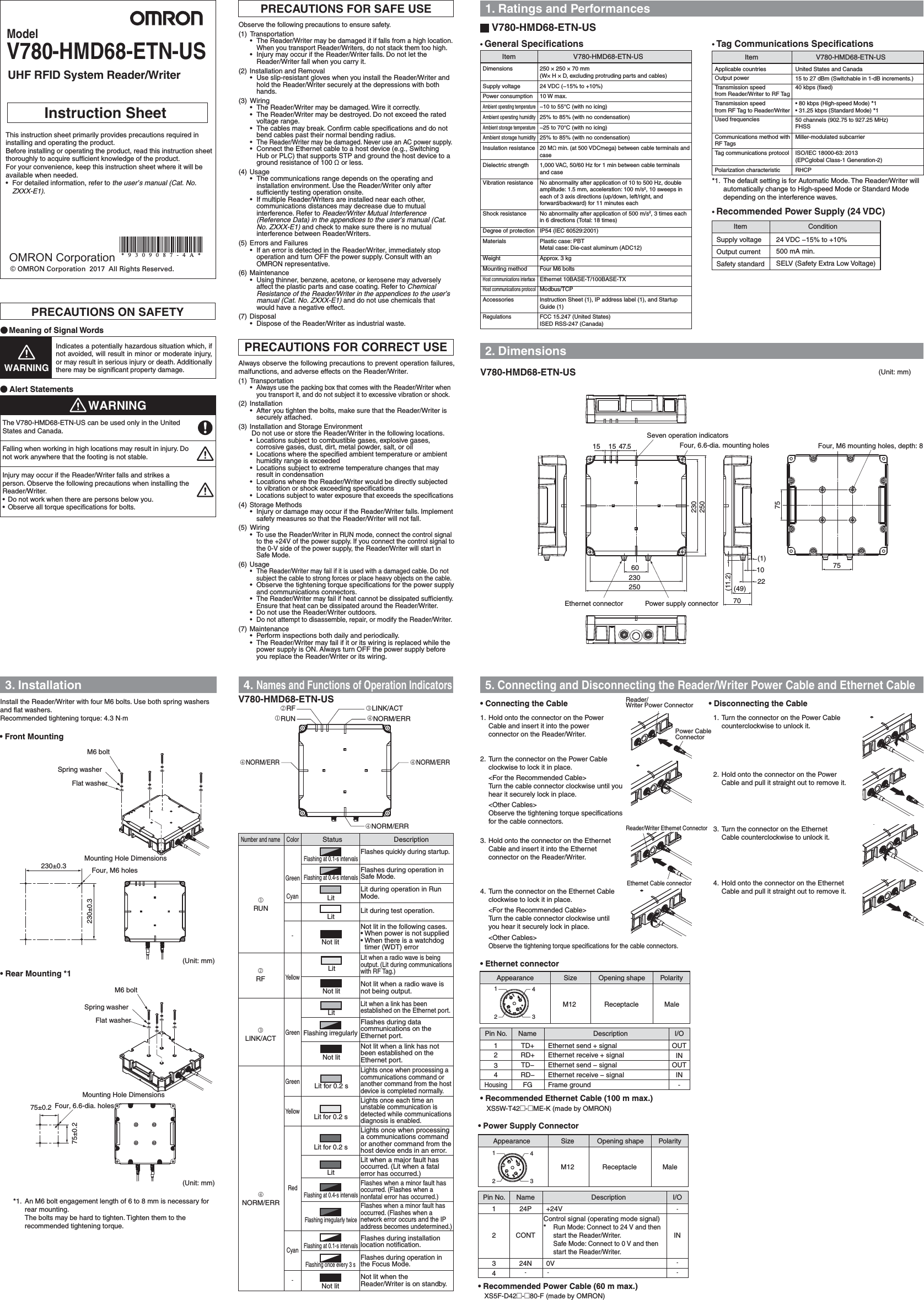
Users manual-1
2.
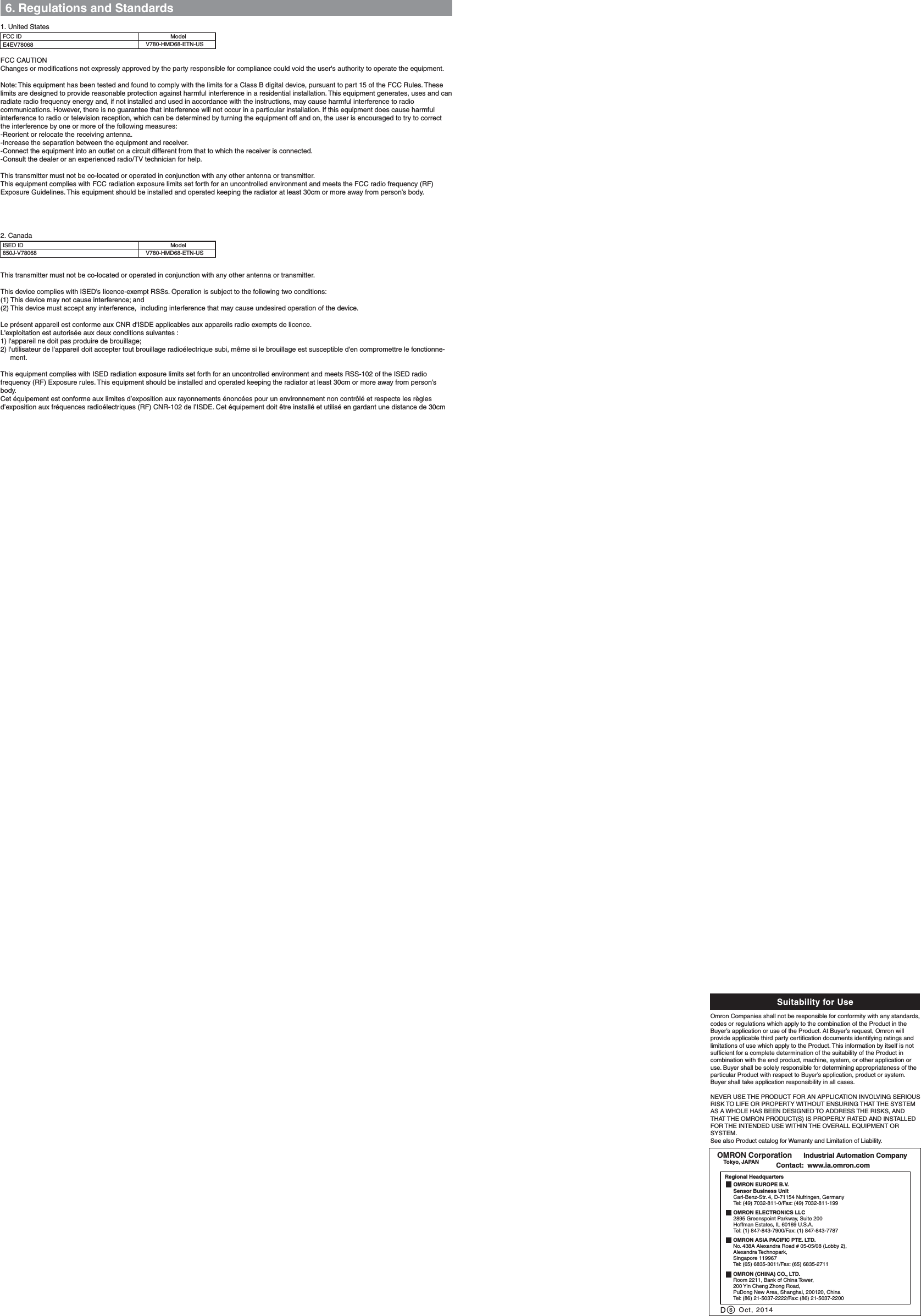
Users manual-2
Users manual-1
Navigation menu
Upload a User Manual
Namespaces
Wiki Guide
HTML
PDF
Info
Views
User Manual
Discussion / Help
Navigation